Release 2.9.0 (r2020-1)
Copyright © 2020 Pi Innovo
13-Apr-2020
Table of Contents
- Foreword
- 1. Introduction
- 2. Installation
- 2.1. Introduction
- 2.2. Installing OpenECU
- 2.3. License setup
- 2.4. Removing OpenECU
- 2.5. Integration notes for third party tools
- 2.5.1. Microsoft Windows 10
- 2.5.2. Microsoft Windows 7
- 2.5.3. Microsoft Windows XP
- 2.5.4. MATLAB
- 2.5.5. PiSnoop
- 2.5.6. ATI Vision
- 2.5.7. ETAS INCA calibration tool
- 2.5.8. Vector CANape
- 2.5.9. Wind River (Diab) C Compiler v5.5.1.0
- 2.5.10. Wind River (Diab) C Compiler v5.8.0.0
- 2.5.11. Wind River (Diab) C Compiler v5.9.0.0
- 2.5.12. GCC Compiler v4.7.3
- 2.5.13. Python
- 3. Quick start
- 4. Software overview
- 4.1. How to find OpenECU
- 4.2. Introduction to OpenECU
- 4.3. Simulink and OpenECU
- 4.4. System modes
- 4.5. Programming an ECU
- 4.6. OpenECU blockset features
- 4.6.1. Calibration tool support
- 4.6.2. Adaptive parameters
- 4.6.3. Communications
- 4.6.4. Compiler options
- 4.6.5. Deprecated blocks
- 4.6.6. Fault support
- 4.6.7. PID support
- 4.6.8. Freeze Frame support
- 4.6.9. Service $09 InfoType support
- 4.6.10. IUPR support
- 4.6.11. Analogue and digital inputs
- 4.6.12. Oxygen sensing — wide band UEGO
- 4.6.13. Operating system
- 4.6.14. Analogue and digital outputs
- 4.6.15. Real-Time Workshop (RTW) support
- 4.6.16. Target ECU identification and configuration
- 4.6.17. Timing
- 4.6.18. Utilities
- 4.6.19. Versioning
- 4.7. Adapting an existing model for OpenECU
- 4.8. Migrating between versions of Simulink
- 5. Design and modelling
- 6. Software detail
- 6.1. OpenECU blockset reference
- 6.1.1. 1-d calibration map look-up and interpolation (put_Calmap1d)
- 6.1.2. 2-d calibration map look-up and interpolation (put_Calmap2d)
- 6.1.3. Application build date (psc_AppBuildDate)
- 6.1.4. Application version (psc_AppVersion)
- 6.1.5. Analogue input — basic (pai_BasicAnalogInput)
- 6.1.6. Analogue input — processed (pai_AnalogInput)
- 6.1.7. Analogue output (pax_AnalogOuput)
- 6.1.8. Build model (prtw_Build)
- 6.1.9. Boot code build date (psc_BootBuildDate)
- 6.1.10. Boot code version (psc_BootVersion)
- 6.1.11. Boot code part number (psc_BootPartNumber)
- 6.1.12. CAN bus status (pcx_BusStatus)
- 6.1.13. CAN configuration (pcx_CANConfiguration)
- 6.1.14. CAN receive message (pcx_CANReceiveMessage)
- 6.1.15. CAN transmit message (pcx_CANTransmitMessage)
- 6.1.16. CANdb message receive (pcx_CANdb_ReceiveMessage)
- 6.1.17. CANdb transmit message (pcx_CANdb_TransmitMessage)
- 6.1.18. CAN status — deprecated (pcx_CANStatus)
- 6.1.19. CCP configuration (pcp_CCPConfiguration)
- 6.1.20. CCP raster configuration (pcp_RasterConfig)
- 6.1.21. CCP seed/key security (pcp_CCPSecurity)
- 6.1.22. CCP inhibit reprogramming (pcp_CCPInhibitReprogramming)
- 6.1.23. CCP CRO receive count (pcp_CCPRxCount)
- 6.1.24. Compiler options (pcomp_CompileOptions)
- 6.1.25. Configure auto-coder (RTW EC) (prtw_ConfigUsingRtwEc)
- 6.1.26. Configure auto-coder (RTW RTMODEL) (prtw_ConfigUsingRtwRtmodel)
- 6.1.27. Configuration M250 (pcfg_Config_M250)
- 6.1.28. Configuration M460 (pcfg_Config_M460)
- 6.1.29. Configuration M670 (pcfg_Config_M670)
- 6.1.30. Constant current output (pax_CcOutput)
- 6.1.31. Constant current output — configuration for TLE8242-2 outputs (pax_CcConfigTle8242)
- 6.1.32. Constant current output — autozero for TLE8242-2 channels (pax_CcAutozeroTle8242)
- 6.1.33. Constant current output — monitor for TLE8242-2 channels (pax_CcReadCurrentTle8242)
- 6.1.34. Debounce (put_Debounce)
- 6.1.35. DTC clear all (pdtc_ClearAll)
- 6.1.36. DTC clear all if active (pdtc_ClearAllIfActive)
- 6.1.37. DTC clear all if inactive (pdtc_ClearAllIfInactive)
- 6.1.38. DTC diagnostic trouble code (pdtc_DiagnosticTroubleCode)
- 6.1.39. DTC enable periodic lamp updates (pdtc_EnablePeriodicLampUpdates)
- 6.1.40. DTC memory update (pdtc_Memory)
- 6.1.41. DTC table definition (pdtc_Table)
- 6.1.42. Digital input (pdx_DigitalInput)
- 6.1.43. Digital output (pdx_DigitalOutput)
- 6.1.44. Digital output monitor (pdx_Monitor)
- 6.1.45. Digital data input (pdd_DataInput)
- 6.1.46. Fault check (put_FaultCheck)
- 6.1.47. Frequency input (pdx_FrequencyInput)
- 6.1.48. Hall decode input measurement (pdx_HallDecodeInput)
- 6.1.49. H-Bridge output (pdx_HBridgeOutput)
- 6.1.50. J1939 configuration (pj1939_Configuration)
- 6.1.51. J1939 channel configuration (pj1939_ChannelConfiguration)
- 6.1.52. J1939 DM1 receive (pj1939_Dm1Receive)
- 6.1.53. J1939 DM1 decode DTC (pj1939_Dm1DecodeDtc)
- 6.1.54. J1939 DM1 transmit (pj1939_Dm1Transmit)
- 6.1.55. J1939 DM2 receive (pj1939_Dm2Receive)
- 6.1.56. J1939 DM2 decode DTC (pj1939_Dm2DecodeDtc)
- 6.1.57. J1939 DM2 transmit (pj1939_Dm2Transmit)
- 6.1.58. J1939 parameter group receive message (pj1939_PgReceive)
- 6.1.59. J1939 parameter group requested (pj1939_PgRequested)
- 6.1.60. J1939 parameter group transmit (pj1939_PgTransmit)
- 6.1.61. Link options (pcomp_LinkOptions)
- 6.1.62. Memory configuration (pmem_MemoryConfiguration)
- 6.1.63. Model identification (put_Identification)
- 6.1.64. Non-volatile adaptive check-sum (pnv_AdaptiveChecksum)
- 6.1.65. Non-volatile adaptive 1-d map look-up (pnv_AdaptiveMap1d)
- 6.1.66. Non-volatile adaptive 2-d map look-up (pnv_AdaptiveMap2d)
- 6.1.67. Non-volatile adaptive scalar (pnv_AdaptiveScalar)
- 6.1.68. Non-volatile adaptive array (pnv_Array)
- 6.1.69. Non-volatile memory status (pnv_Status)
- 6.1.70. Output control (pss_OutputControl)
- 6.1.71. Over-current trip reset (pss_OvercurTripReset)
- 6.1.72. Over current trip reset and diagnostic enable (pss_OvercurTripReset_DiagnEnable)
- 6.1.73. Peak and hold injector output (pdx_PeakHoldInjectorOutput)
- 6.1.74. Internal RAM test error (psc_InternalRamTestError)
- 6.1.75. Internal RAM test progress (psc_InternalRamTestProgress)
- 6.1.76. Internal ROM test error (psc_InternalRomTestError)
- 6.1.77. Internal ROM test progress (psc_InternalRomTestProgress)
- 6.1.78. Platform code build date (psc_PlatformBuildDate)
- 6.1.79. Platform code version (psc_PlatformVersion)
- 6.1.80. Platform code part number (psc_PlatformPartNumber)
- 6.1.81. Processor loading (psc_CpuLoading)
- 6.1.82. eTPU loading (psc_EtpuLoading)
- 6.1.83. PWM input measurement (pdx_PwmInput)
- 6.1.84. PWM output — fixed frequency (pdx_PWMOutput)
- 6.1.85. PWM output — variable frequency (pdx_PWMVariableFrequencyOutput)
- 6.1.86. PWM output — with synchronous sampling (pdx_PWMOutputWithSyncSampling)
- 6.1.87. Quadrature decode input (pdx_QuadratureDecode)
- 6.1.88. Quadrature decode and frequency input measurement (pdx_QuadratureDecodeAndFrequencyInput)
- 6.1.89. Range check (put_RangeCheck)
- 6.1.90. Reset module (put_Reset)
- 6.1.91. Reset count — stable (psc_ResetCount)
- 6.1.92. Reset count — unstable (psc_UnstableResetCount)
- 6.1.93. Reprogramming code build date (psc_PrgBuildDate)
- 6.1.94. Reprogramming code version (psc_PrgVersion)
- 6.1.95. Reprogramming code part number (psc_PrgPartNumber)
- 6.1.96. Retrieve registry key (preg_RetrieveKey)
- 6.1.97. Require platform version (put_RequirePlatformVersion)
- 6.1.98. Show Simulink's sample time colours (prtw_ShowSampleTimeColours)
- 6.1.99. SENT input (pdx_SentInput)
- 6.1.100. SENT input — serial data (pdx_SentSerialInput)
- 6.1.101. Signal gap detection (put_SignalGapDetection)
- 6.1.102. Signal prepare (put_SignalPrepare)
- 6.1.103. Signal validate (put_SignalValidate)
- 6.1.104. Slew rate check (put_SlewRateCheck)
- 6.1.105. SPI communication fault count (psp_FaultCount)
- 6.1.106. Stack used (psc_StackUsed)
- 6.1.107. PWM output — variable frequency, synchronised (pdx_PWMSynchronisedOutput)
- 6.1.108. Task duration (pkn_TaskDuration)
- 6.1.109. Task period overrun (pkn_TaskPeriodOverrun)
- 6.1.110. TargetLink Integration (ptl_TargetLinkSubsystem)
- 6.1.111. Time (real) (ptm_RealTime)
- 6.1.112. Time (Simulink) (ptm_SimulinkTime)
- 6.1.113. UEGO sensor control — CJ125 device (pcj125_Control)
- 6.1.114. Watchdog kick (psc_KickWatchdog)
- 6.1.115. Waveform — configuration, boost voltage (prop_BoostConfig)
- 6.1.116. Waveform — configuration, phases (prop_WaveformConfig)
- 6.1.117. Waveform — set channel (prop_WaveformSetChannel)
- 6.2. Automatic ASAP2 entries
- 6.2.1. Boot build information
- 6.2.2. Reprogramming build information
- 6.2.3. Platform build information
- 6.2.4. Application build information
- 6.2.5. Application and library task timing information
- 6.2.6. Memory use information
- 6.2.7. Memory error correction events
- 6.2.8. Floating point conditions
- 6.2.9. J1939 related information
- 6.3. OpenECU software versioning
- 6.4. OpenECU commands
- 7. Angular detail
- 7.1. Engine position sensor processing
- 7.1.1. Crankshaft position sensor processing
- 7.1.2. Crankshaft position detection
- 7.1.3. Crankshaft zero degrees
- 7.1.4. Angle clock
- 7.1.5. Crank tooth identification
- 7.1.6. Crankshaft speed
- 7.1.7. Multiple crankshaft sensor inputs
- 7.1.8. Camshaft position sensor processing
- 7.1.9. Engine synchronisation modes
- 7.2. Engine TDC-firing events
- 7.3. Analogue input processing
- 7.4. Knock sensor processing
- 7.5. Scheduling injector outputs
- 7.6. Scheduling coil outputs
- 7.7. Scheduling digital outputs
- 7.8. Blockset reference
- 7.8.1. Analogue input — angular, configuration (pan_AngularAnalogInput_Config)
- 7.8.2. Analogue input — angular, variable relative angle (pan_AngularAnalogInputVariable)
- 7.8.3. Analogue input — angular, variable absolute angle (pan_AngularAnalogInputVariableAbs)
- 7.8.4. Cam wheel — configuration (pan_CamWheelConfig)
- 7.8.5. Cam wheel — digital input (pan_CamWheelDigitalInput)
- 7.8.6. Cam wheel — movement (pan_CamWheelMovement)
- 7.8.7. Cam wheel — tooth edge angles (pan_CamWheelToothEdgeAngles)
- 7.8.8. Crank wheel — angle (pan_CurrentCrankAngle)
- 7.8.9. Crank wheel — configuration (pan_CrankWheelConfig)
- 7.8.10. Crank wheel — extended configuration (pan_CrankWheelConfigExt)
- 7.8.11. Crank wheel — digital input (pan_CrankWheelDigitalInput)
- 7.8.12. Crank wheel — decoding (pan_CrankWheelDecodeState)
- 7.8.13. Crank wheel — movement (pan_CrankWheelMovement)
- 7.8.14. Crank wheel — secondary phase angle (pan_CrankSecondaryPhase)
- 7.8.15. Crank wheel — speed (pan_CrankWheelSpeed)
- 7.8.16. Crank wheel — synchronisation (pan_CrankWheelSync)
- 7.8.17. Crank wheel — sync point last (pan_CrankWheelSyncPointLast)
- 7.8.18. Crank wheel — sync point next (pan_CrankWheelSyncPointNext)
- 7.8.19. Crank wheel — sync point trigger (pan_CrankWheelSyncPointTrigger)
- 7.8.20. Crank wheel — tooth (pan_CurrentCrankTooth)
- 7.8.21. Digital output — angular configuration (pan_AngularOutputConfig)
- 7.8.22. Digital output — angular digital (pan_AngularOutput)
- 7.8.23. Engine angle (pan_CurrentEngineAngle)
- 7.8.24. Engine configuration (pan_EngineConfig)
- 7.8.25. Engine cylinder (pan_CurrentCylinder)
- 7.8.26. Engine speed (pan_EngineSpeed)
- 7.8.27. Engine synchronisation (pan_EngineSync)
- 7.8.28. Engine synchronisation — declare mode (pan_EngineDeclareSync)
- 7.8.29. Engine synchronisation — declare loss of synchronisation (pan_EngineLoseSync)
- 7.8.30. Engine tooth (pan_CurrentEngineTooth)
- 7.8.31. Injection configuration — multiple outputs (pan_InjectorConfig)
- 7.8.32. Injection configuration — single output (pan_SingleInjectorConfig)
- 7.8.33. Injection configuration — direct injection (pan_InjectorConfig_DI)
- 7.8.34. Injection configuration — fuel rail pressure compensation (pan_InjectorCompConfig_DI)
- 7.8.35. Injection direct — fuel rail pressure override (pan_InjectionOverrideFrp_DI)
- 7.8.36. Injection direct — set schedule (pan_Injection_DI)
- 7.8.37. Injection direct — setpoint feedback (pan_InjectionSetpoint_DI)
- 7.8.38. Injection direct — event feedback (pan_InjectionFeedback_DI)
- 7.8.39. Injection port — initial fuel pulse (pan_InitialInjection_PI)
- 7.8.40. Injection port — set schedule (pan_Injection_PI)
- 7.8.41. Injection port — update injection schedule (pan_UpdateInjection_PI)
- 7.8.42. Injection port — setpoint feedback (pan_InjectionSetpoint_PI)
- 7.8.43. Injection port — event feedback (pan_InjectionFeedback_PI)
- 7.8.44. Knock configuration (pan_KnockConfig)
- 7.8.45. Knock detection window (pan_KnockDetectionWindow)
- 7.8.46. Knock feedback (pan_KnockFeedback)
- 7.8.47. Knock filter — HIP901x (pan_KnockFilter_Hip901x)
- 7.8.48. Spark configuration (pan_SparkConfig)
- 7.8.49. Spark (pan_Spark)
- 7.8.50. Spark feedback (pan_SparkFeedback)
- 7.8.51. Waveform — configuration, boost voltage (prop_BoostConfig)
- 7.8.52. Waveform — configuration, phases (prop_WaveformConfig)
- 7.8.53. Waveform — set channel (prop_WaveformSetChannel)
- 8. Extended diagnostics functions
- 8.1. Introduction to Diagnostics
- 8.2. Diagnostic Legislation
- 8.3. Approach
- 8.4. Diagnostic trouble codes and freeze-frames
- 8.5. Diagnostic monitors, tests and performance ratios
- 8.6. Worked example — building a diagnostic system
- 8.7. Extended diagnostic Simulink blocks
- 8.7.1. Calibration verification number (CVN) (psc_CvnCalc)
- 8.7.2. DTC clear all (pdtc_ClearAll)
- 8.7.3. DTC clear all if active (pdtc_ClearAllIfActive)
- 8.7.4. DTC clear all if inactive (pdtc_ClearAllIfInactive)
- 8.7.5. DTC match and clear (pdtc_ClearDtcs)
- 8.7.6. DTC control (pdtc_Control)
- 8.7.7. DTC diagnostic trouble code (extended) (pdtc_DiagnosticTroubleCodeExt)
- 8.7.8. DTC lamp states (pdtc_Status)
- 8.7.9. DTC match exists (pdtc_MatchExists)
- 8.7.10. DTC memory update (pdtc_Memory)
- 8.7.11. DTC table definition (pdtc_Table)
- 8.7.12. DTC table cleared indication (pdtc_TableCleared)
- 8.7.13. ISO configuration (piso_Configuration)
- 8.7.14. ISO security permissions (pdg_Permissions)
- 8.7.15. ISO DTC extended data records (pdg_ExtendedDataRecord)
- 8.7.16. Routine control (pdg_RoutineControl)
- 8.7.17. Parameter identifier (ppid_Pid)
- 8.7.18. Parameter identifier scaling (ppid_Scaling)
- 8.7.19. Freeze frame (pff_FreezeFrame)
- 8.7.20. DM25 freeze frame (pff_Dm25FreezeFrame)
- 8.7.21. Freeze frame configuration (pff_Configuration)
- 8.7.22. J1939 configuration (pj1939_Configuration)
- 8.7.23. J1939 channel configuration (pj1939_ChannelConfiguration)
- 8.7.24. J1939 Transmit DTC DM (pj1939_TransmitDtcDm)
- 8.7.25. J1939 DM1 receive (pj1939_Dm1Receive)
- 8.7.26. J1939 DM1 decode DTC (pj1939_Dm1DecodeDtc)
- 8.7.27. J1939 DM1 transmit (pj1939_Dm1Transmit)
- 8.7.28. J1939 DM2 receive (pj1939_Dm2Receive)
- 8.7.29. J1939 DM2 decode DTC (pj1939_Dm2DecodeDtc)
- 8.7.30. J1939 DM2 transmit (pj1939_Dm2Transmit)
- 8.7.31. J1939 DM4 transmit (pj1939_Dm4Transmit)
- 8.7.32. J1939 DM5 transmit (pj1939_Dm5Transmit)
- 8.7.33. J1939 DM7 decode (pj1939_Dm7Decode)
- 8.7.34. J1939 DM8 transmit (pj1939_Dm8Transmit)
- 8.7.35. J1939 DM10 transmit (pj1939_Dm10Transmit)
- 8.7.36. J1939 DM20 transmit (pj1939_Dm20Transmit)
- 8.7.37. J1939 DM21 transmit (pj1939_Dm21Transmit)
- 8.7.38. J1939 DM24 transmit (pj1939_Dm24Transmit)
- 8.7.39. J1939 DM25 transmit (pj1939_Dm25Transmit)
- 8.7.40. J1939 DM26 transmit (pj1939_Dm26Transmit)
- 8.7.41. J1939 DM30 transmit (pj1939_Dm30Transmit)
- 8.7.42. J1939 DM32 transmit (pj1939_Dm32Transmit)
- 8.7.43. J1939 DM33 transmit (pj1939_Dm33Transmit)
- 8.7.44. J1939 DM34 transmit (pj1939_Dm34Transmit)
- 8.7.45. J1939 DM35 transmit (pj1939_Dm35Transmit)
- 8.7.46. J1939 DM36 transmit (pj1939_Dm36Transmit)
- 8.7.47. J1939 DM37 transmit (pj1939_Dm37Transmit)
- 8.7.48. J1939 DM38 transmit (pj1939_Dm38Transmit)
- 8.7.49. J1939 DM39 transmit (pj1939_Dm39Transmit)
- 8.7.50. J1939 DM40 transmit (pj1939_Dm40Transmit)
- 8.7.51. J1939 parameter group receive message (pj1939_PgReceive)
- 8.7.52. J1939 parameter group requested (pj1939_PgRequested)
- 8.7.53. J1939 parameter group transmit (pj1939_PgTransmit)
- 8.7.54. J1939 send acknowledgement message (pj1939_SendAck)
- 8.7.55. J1939 update NTE status (pj1939_UpdateNteStatus)
- 8.7.56. J1979 service $09 Infotype input (pdg_InfotypeInput)
- 8.7.57. Diagnostic monitor entity (ppr_DiagnosticMonitorEntity)
- 8.7.58. Diagnostic test entity (ppr_DiagnosticTestEntity)
- 8.7.59. General denominator (ppr_GeneralDenominator)
- 8.7.60. Ignition cycle (ppr_IgnitionCycle)
- 8.7.61. PPR memory update (ppr_Memory)
- 8.7.62. Monitors incomplete count (ppr_MonitorsIncomplete)
- A. Reference documentation
- B. Supporting tools
- C. Examples
- D. Memory configurations
- E. ASAP2 compliance
- F. CCP compliance
- G. CCP troubleshooting guide
- H. Data dictionary tool errors
- I. Change log
- J. Glossary of terms
- K. Contact information
List of Figures
- 3.1. OpenECU integrated with MATLAB's launch pad
- 3.2. Quick start loom
- 3.3. Connected quick start model
- 3.4. Analogue input transfer function
- 3.5. Configured quick start model
- 3.6. Updated quick start model
- 4.1. OpenECU integrated with Window's Start button
- 4.2. OpenECU integrated with MATLAB's help system (R2015a - R2015b)
- 4.3. OpenECU integrated with MATLAB's help system (R2016a - R2020a)
- 4.4. OpenECU integrated with MATLAB's library browser (R2015a - R2020a)
- 4.5. Example development pattern for modelling an application
- 4.6. Breaking the input and output processing from the application
- 4.7. Simulink's Model Explorer showing OpenECU configuration sets
- 4.8. Building an application (in outline)
- 4.9. System modes
- 4.10. System modes for M220, M250, M460 and M461
- 4.11. System modes for M110, M221 and M670
- 4.12. Signal update rates
- 4.13. Signal update rates
- 6.1. TLE8242-2 constant current control diagram
- 6.2. TLE8242-2 KP and KI equations
- 6.3. J1939 DTC states
- 6.4. Sector configuration for a 3 phase hall input - 60° spacing
- 6.5. Sector output encoding
- 6.6. Sensor outputs with 60° spacing
- 6.7. Sector configuration and outputs for 120° sensor spacing
- 6.8. Output of H-Bridge during mode transition
- 6.9. Quadrature encoder and generated signals
- 6.10. Direction of encoder and generated signals
- 6.11. Pulse count example
- 6.12. Quadrature encoder and generated signals
- 6.13. Direction of encoder and generated signals
- 6.14. Pulse count example
- 6.15. Disabling naming convention
- 6.16. Disabling Simulink ASAP2 generation
- 6.17. Example time-line to explain the ptm_RealTime block
- 6.18. Example time-line to explain the ptm_SimulinkTime block
- 6.19. Three stage, waveform
- 7.1. Output pulse - Angle-Time Duration (turn-on/turn-off)
- 7.2. Output pulse - Angle-Time Duration (turn-on/no-action)
- 7.3. Output pulse - Angle-Angle Duration (turn-off/toggle)
- 7.4. Output pulse - Angle-Angle Duration (turn-on/turn-off)
- 7.5. Output data updated during an event, end modification allowed
- 7.6. Output data updated during an event, end modification not allowed
- 7.7. Output event with overlap between two events
- 7.8. Output event starting within minimum off time
- 7.9. Multiple injection pulses
- 7.10. Injection constraints
- 7.11. Main injection event
- 7.12. Injector pulse duration is composed of dead time and flow time
- 7.13. Clipped injection event
- 7.14. Injection events in 360° mode
- 7.15. Post injection events
- 7.16. Knock window schedule
- 7.17. Knock signal processing for the HIP901x family of processors
- 7.18. Spark event relative to cylinder's TDC-firing angle
- 7.19. Spark event relative to cylinder's TDC-firing angle
- 8.1. Functional Levels within a Diagnostics System
- 8.2. Scan tool link via platform
- 8.3. Use of PID blocks to collect data
- 8.4. Building a diagnostic system — monitor level
- 8.5. Building a diagnostic system — individual test
- 8.6. Building a diagnostic system — warning lamps
- 8.7. Building a diagnostic system — generic counters
- 8.8. J1939 request/response example
- 8.9. Platform OBD state machine - no transitions between Previously Active and Pending
- 8.10. Platform OBD state machine - transitions between Previously Active and Pending
- 8.11. Freeze frame capture and deletion
List of Tables
- 2.1. Third party tool compatibility
- 2.2. Install components
- 3.1. Step1 - model identification block parameters
- 3.2. Step1 - CAN configuration block parameters
- 3.3. Step1 - CCP configuration block parameters
- 3.4. Step1 - analogue input block parameters
- 3.5. Step1 - PWM output block parameters
- 3.6. Simulink model colouring
- 3.7. FEPS voltages
- 4.1. Standard MATLAB commands
- 4.2. Data dictionary columns
- 4.3. Simulink data dictionary object properties
- 4.4. Simulink data dictionary object storage classes
- 4.5. FEPS voltages
- 4.6. ASAP2 naming schemes
- 4.7. FEPS voltages
- 4.8. Library and application tasks
- 4.9. Model simulation settings for R2015a
- 4.10. Model simulation settings for R2015b
- 4.11. Model simulation settings for R2016a
- 4.12. Model simulation settings for R2016b
- 4.13. Model simulation settings for R2017a
- 4.14. Model simulation settings for R2017b
- 4.15. Model simulation settings for R2018a and R2018b
- 4.16. Model simulation settings for R2019a, R2019b, and R2020a
- 5.1. Variable naming convention
- 5.2. 1-d map lookup naming convention
- 5.3. 2-d map lookup naming convention
- 6.1. Interval notation
- 6.2. CAN block type codes
- 6.3. CCP defaults
- 6.4. Generic pin naming convention
- 6.5. Supported Key/Value pairs
- 6.6. CAN signal gap error codes
- 6.7. CAN signal prepare invalid codes.
- 6.8. CAN signal validate error codes.
- 6.9. Automatic ASAP2 entries for boot build information
- 6.10. Automatic ASAP2 entries for reprogramming build information (M220, M221, M250, M460, M461, M670)
- 6.11. Automatic ASAP2 entries for platform build information
- 6.12. Automatic ASAP2 entries for application build information
- 6.13. Automatic ASAP2 entries for application rate task timing information
- 6.14. Automatic ASAP2 entries for auxiliary task timing information
- 6.15. Automatic ASAP2 entries for CPU loading information
- 6.16. Automatic ASAP2 entries for eTPU loading information
- 6.17. Automatic ASAP2 entries for maximum application rate task timing information
- 6.18. Automatic ASAP2 entries for run-time information
- 6.19. Automatic ASAP2 entries for reset information (M110, M220, M250, M460, M461)
- 6.20. Automatic ASAP2 entries for number of instances of period overruns of periodic tasks
- 6.21. Automatic ASAP2 entries for memory use information
- 6.22. Automatic ASAP2 entries for memory error correction events
- 6.23. Automatic ASAP2 entries for floating point conditions
- 6.24. Automatic ASAP2 entries for J1939 related information
- 6.25. Software component versions (for M110-000)
- 6.26. Software component versions (for M220-000)
- 6.27. Software component versions (for M220-0AU)
- 6.28. Software component versions (for M221-000)
- 6.29. Software component versions (for M250-000)
- 6.30. Software component versions (for M460-000)
- 6.31. Software component versions (for M461-000)
- 6.32. Software component versions (for M670-000)
- 7.1. Function availability based on engine synchronisation mode
- 7.2. Crankshaft signal decoding error bitmap values
- 7.3. Angular digital output pin actions
- 7.4. Function availability based on engine synchronisation mode
- 7.5. Function availability based on engine synchronisation mode
- 8.1. Diagnostic Service Comparisons
- 8.2. PDG supported services
- 8.3. DTC initialisation values
- 8.4. RoutineControl request sub-function
- 8.5. InputOutputControl Status (KW2000-3 draft)
- D.1. Memory configurations supported
- D.2. Memory configurations supported
- D.3. Memory configurations supported
- F.1. Supported CCP commands
- F.2. Supported CCP commands (in older versions of ECUs)
- F.3. Original EXCHANGE_ID message
- F.4. Modified EXCHANGE_ID message
- F.5. EXCHANGE_ID selection values
- F.6. EXCHANGE_ID manufacturing data key values and binary format
- I.1. Release summary for v2.9.0-r2020-1
Before using OpenECU, it is very important to read and understand the warning and safety information given in Section 1.7, “Warnings and safety guidelines” and in Section 1.8, “Warning”.
Pi, the Pi logo and OpenECU are trademarks of Pi Innovo Ltd. Microsoft, Windows, Excel, Word, MATLAB, Simulink, StateFlow, Vision, CANape and INCA are all registered trademarks of their respective owners.
Pi Innovo makes no representation or warranties of any kind whatsoever with respect to the contents hereof, and specifically disclaims any implied warranties of merchantability or fitness for any particular purpose. Pi Innovo shall not be liable for any errors contained herein, or for incidental or consequential damages in connection with the furnishing, performance or use of the software, associated hardware, or this written material.
Pi Innovo reserves the right to revise this publication from time to time, and to make changes in the content hereof without obligation to notify any person of such revision or changes.
A copy of the Pi Innovo Terms and Conditions of Sale is available on request, and includes a declaration of the warranty and limitation of liability which apply to all Pi Innovo products and services.
Under the terms of European and UK Health and Safety Legislation, Pi Innovo is required to classify any hazardous materials in the products it supplies and to provide relevant safety information to users.
Any hazardous materials in Pi products are clearly marked with appropriate symbols. Product Safety Data Sheets relating to these materials are available on request.
Thank you for choosing Pi Innovo's OpenECU platform.
Pi Innovo's OpenECU platform offers a new solution to engine and vehicle control system development. Based on Pi's extensive experience of ECU development, and backed by Pi's unrivalled capabilities in project and customer support, OpenECU helps you get quickly to what you need: working, robust control systems.
By using production ECU hardware as an auto-code platform, you gain all the advantages of auto-coding and rapid prototyping, but with hardware that meets full production environmental and packaging requirements (see Section A.1, “ECU hardware reference documentation” for environmental and packaging details).
The OpenECU system consists of:
a range of production ECU hardware modules for engines with up to 8 cylinders (or more with multiple modules);
an optional range of tested engine and vehicle control strategies, from individual functional blocks to complete strategy suites;
a comprehensive range of support and consultancy services, ranging from sensor selection and system design advice through to complete bespoke system development.
Applications of the OpenECU platform include:
engine control system development;
chassis control system development;
transmission control system development;
hybrid powertrain control system development;
vehicle fleet trials.
For support contact information, please see the last page of this manual.
Simulink is a powerful simulation and analysis software engine which is used throughout academia and industry to develop and analyse dynamic systems.
Simulink is a widely used software package for modelling, simulating and analysing dynamic systems, which is based upon the MATLAB software engine. It allows you to build graphical models of linear and non-linear systems, using a simple drag-and-drop interface and a library of functional blocks. You can then simulate your model under dynamic running conditions to analyse its behaviour, and continuously interact with the parameters while the simulation is running.
Many functional blocks are included in the standard Simulink library, allowing you to model any system whose dynamics you want to simulate. This library is supplemented by Pi's OpenECU blocks, which are specialised for use with the OpenECU platform.
There are several OpenECU packages available from Pi, which can include the following items.
The following items of hardware are available as part of OpenECU:
- Electronic Control Unit (ECU)
This is the computer that monitors and controls all aspects of the electronic system's behaviour. Code generated from your Simulink model is programmed into the ECU. There are four different models of ECU currently available — 4 in-line cylinder and V8 cylinder, in both development and fleet models (see Section A.1, “ECU hardware reference documentation” for further details).
- Connectors
All the connectors and terminals required to connect the ECU, the calibration tool and your PC together.
- Tools
You will require a crimping tool for the ECU connectors. Pi Innovo will give you details on request.
The following items of software are available as part of OpenECU:
- Complete OpenECU strategy suites (optional)
These are complete Simulink models that simulate all the control functionality of an entire engine or other dynamic system. Complete strategies comprise many levels of design and modelling, and are the product of many years of design research and testing at Pi Innovo. Complete strategies are available for petrol (I4 and V8 cylinder) systems.
- OpenECU Simulink strategies (optional)
These are complete Simulink models that have been designed to simulate whole blocks of engine control functionality, such as spark generation, rev limiting, etc. They are the blocks from which the complete strategy suites (above) are developed. Designed by Pi, they can be integrated with your own models, and are used in exactly the same way as all Simulink blocks.
- OpenECU Simulink blocks
These functional blocks supplement those that are normally available in Simulink, and are used to create inputs, outputs and signal processing capabilities for engine-related functions such as angle calculations, spark timings, etc. They are designed by Pi, and form the platform for higher-level engine functionality, but are used in exactly the same way as all Simulink blocks. They are the blocks from which the strategies (above) are developed.
And the following items of software are required but not provided as part of OpenECU.
- Calibration Tool
This electronic tool is used to program the auto-generated code into the ECU, and to monitor (and, in some cases, alter) the values of certain parameters while the ECU is running. Pi's own PiSnoop product is one option, along with several industry-standard alternatives, and we will be able to recommend a suitable product on request.
- Compiler
A tool which takes the Simulink generated code representing the graphical model and turns it into an executable image that can be run on OpenECU hardware.
OpenECU allows for several different options enabling different features. The licensing system retains control of the ability to use these features depending on what the customer has purchased.
The current set of available features is:
OPENECU
The main feature. Enabled when you purchase any version of OpenECU
CAPI_BUILD
Allows for building OpenECU applications with the C-API. This feature is also a prerequisite for SIMULINK_BUILD.
SIMULINK_SIMULATE
Allows for simulation of OpenECU models in Simulink. This feature is also a prerequisite for SIMULINK_BUILD.
SIMULINK_BUILD
Allows for building OpenECU models with the Sim-API. Because the Sim-API wraps the C-API, both features are required to build OpenECU Simulink models
EXT_DIAG
Extended diagnostics features.
- Allows use of the Extended diagnostics blockset in Simulink models.
- Allows use of the Extended diagnostics library functions at run time in OpenECU applications
To make the best use of OpenECU, certain hardware, software and knowledge requirements need to be fulfilled, as described below.
To run the Pi OpenECU software with MATLAB and Simulink, you will need an IBM-compatible PC with the minimum specifications listed below. These specifications are the same as those for running MATLAB:
CPU: a modern Intel or AMD x86 32-bit or 64-bit processor.
RAM: 2 GiB minimum, but more recommended (larger models will require more RAM).
Free hard disk space: 2 GiB.
Peripheral hardware: keyboard, mouse, DVD/CD-ROM drive (for installation from CD media), at least 8-bit graphics adapter and display (for at least 256 colours).
Either the physical system or a system simulator, is ultimately required to test and calibrate your ECU and the system model you have created to run on it. A suitable Calibration/reprogramming communications tool is also required conforming to the ASAP2 standard.
You will need the following software pre-installed on your PC:
Operating system: Microsoft Windows 10 or Microsoft Windows7 SP1 32-bit or 64-bit.
MathWorks: MATLAB and Simulink (and optionally, Stateflow and Stateflow Coder):
See OpenECU Compatibility with Third Party Tools for a complete list of supported versions.
MathWorks: Simulink Coder (formerly Real-Time Workshop) versions:
See OpenECU Compatibility with Third Party Tools for a complete list of supported versions.
Wind River Diab compiler; version 5.5.1.0 (M220, M221, M250, M460 and M461); or version 5.8.0.0 (M220, M221, M250, M460 and M461); or version 5.9.0.0 (M220, M221, M250, M460, M461 and M670). Only the C language version is required (note, C++ is not yet supported).
Calibration tool: PiSnoop, ATI Vision™ (version 2.5 through 5.1.2), ETAS INCA (version 7.2.7) or Vector CANape (version 8.0 through 16.0).
Note
OpenECU developer software does not support earlier versions of Windows than XP (SP3), Windows Vista, or Windows 8.
See the Chapter 2, Installation for full details of the software required.
This manual describes how to incorporate the OpenECU Simulink blocks provided by Pi Innovo into your own designs, but does not include a MATLAB or Simulink guide or tutorial. Please refer to the user guides that accompany that software for full installation and operating instructions.
A working knowledge of design modelling and system dynamics principles in an engineering environment is required to make the best use of Simulink and OpenECU. Ultimately, it is the quality of your own system designs that will be reflected in the quality of your system control strategy.
Note also that there are serious hardware and personal safety considerations involved in developing automotive control systems. Please make sure that you read and understand the Safety and Warning section at the end of this chapter to reduce the chance of any such hazards.
The OpenECU design and build process is comprised of the following steps:
Design a model of your system, using Simulink library blocks, and optionally those blocks that Pi Innovo has developed and included for the OpenECU platform. If you have purchased a complete engine strategy suite, this will have been done for you. This process will typically have many cycles of design and HIL (hardware-in-loop) testing.
Once you are satisfied that your model simulation functions within your design parameters, the C code can be auto-generated from Simulink.
The C code is passed to the compiler, which generates the executable for the ECU operating system. This is then programmed into the ECU using the Calibration Tool.
The ECU is then connected to either the physical system or a system simulator (e.g. Pi AutoSim). There then follows a cycle of calibration and testing to optimise the model and its parameters to the particular characteristics of the target system (or simulator). This may involve returning to the Simulink model to adapt its design.
Pi Innovo has over 14 years of experience designing powertrain controllers, working closely with customers to get to the best possible control system solution. Millions of cars and trucks on the road use Pi-designed engine control.
OpenECU comes with a wide range of options for customer and project support, allowing you to draw on over 500 man-years of control system design experience. Whichever option you choose, you can count on real commitment from Pi to provide what you need, and to go the extra mile.
For contact information, refer to Appendix K, Contact information.
It is very important to read and understand the following warnings and safety guidelines. Inappropriate use of the OpenECU system can lead to loss of data, damage to software and hardware, and possible personal injury if safe vehicle operation is compromised.
The safe operation of OpenECU is the responsibility of the those using it. The level of risk associated with the user's application must be ascertained and appropriate mitigation devices used to reduce the potential risks to an acceptable level. These mitigation devices may include a system 'kill switch', driver training, backup systems and use of the vehicle in safe environments.
A structured approach to testing is recommended, particularly before the product is used in environments where it may be in contact with members of the public (e.g. the public highway). This testing may include HIL, static vehicle system test and/or vehicle test in a test track environment.
Pi Innovo supplies OpenECU on the basis that:
The responsibility for ensuring that the use of OpenECU is safe lies with the customer.
The customer will include appropriate mitigation devices as identified by the hazard analysis they perform (such as engine kill switch, back up devices).
The user will read all OpenECU documentation (including this document) to ensure its safe use.
OpenECU is not to be used in safety critical applications, e.g. aerospace.
OpenECU is to be used in a system development environment only.
OpenECU is not to be sold to the public.
All users must be competent to make appropriate safety judgements.
Pi Innovo also strongly recommends that:
Applications be developed using a process suitable for the application.
HIL testing be used prior vehicle testing.
"Off public highway" vehicle testing be performed prior to road testing.
Pi Innovo considers the safety and quality of its products to be of paramount importance. The integrity of the product can be considered by assessing the three 'components' which comprise the system.
Systems, rather than software, have a Safety Integrity Level (SIL). The SIL of the customer's resultant system will have to be assessed and defined by their knowledge of the processes used to develop all the components (including those supplied by Pi) comprising the complete system.
The hardware is a production unit (see Section A.1, “ECU hardware reference documentation” for module environmental specifications). However different applications will have different requirements for output monitoring. Those outputs that are selected (by the customer) to drive safety related outputs should include output monitor circuits. The use of outputs for critical devices which do not contain a monitor feedback is strongly discouraged.
The platform comprises functionality which allows the high level strategy to operate in the specific hardware target (electronic box). It includes:
This suite of software is predominantly hand-coded with some additional auto-coded Simulink models.
OpenECU has been developed using a lean SIL0 process enabling its rapid introduction to the market place. This process included internal review, module testing and considerable vehicle testing. It is considered to be a reliable and robust platform on which to build vehicle control applications.
The configuration of the platform is the customer's responsibility. It is entirely possible, through careless configuration, to 'cross wire' inputs or outputs for example. This could, for example, lead to injector 1 firing when you intended injector 2 to fire. The mis-calibration of analogue inputs could lead to undesired behaviour such as steering angle or accelerator pedal position to be mis-calculated.
Documented vehicle prove out tests should mitigate against this leading to severe outcomes.
The strategy may be developed entirely by the customer, or be a development by the customer of generic libraries supplied by Pi Innovo. In either case the integrity of the resultant strategy model must be the responsibility of the customer.
Pi's generic libraries have been extensively validated via module testing, HIL system testing and vehicle testing but have not undergone unit testing.
The supplied libraries have been validated for a specific application and a specific hardware set. The user MUST validate the correct function of the strategies in their application.
The process of testing automotive systems can involve many personal safety hazards — high-speed machinery, extremely flammable and potentially explosive fuels, and the possibility of loss of vehicle control is a combination that can be fatal if sensible precautions are not followed.
As the system designer and tester, it is your responsibility to ensure that your working practices are specifically designed to minimise or eliminate the possibility of personal injury, and to incorporate into your designs such fail-safe functionality as is necessary. This includes the avoidance of certain dynamical situations such as open throttles and other 'positive feedback' scenarios where control of the system may be lost.
Pi Innovo makes no representation or warranties of any kind whatsoever with respect to the contents hereof, and specifically disclaims any implied warranties of merchantability or fitness for any particular purpose. Pi Innovo shall not be liable for any errors contained herein, or for incidental or consequential damages in connection with the furnishing, performance or use of the software, associated hardware, or this written material.
Pi Innovo reserves the right to revise this publication from time to time, and to make changes in the content hereof without obligation to notify any person of such revision or changes.
A copy of the Pi Innovo Terms and Conditions of Sale is available on request, and includes a declaration of the warranty and limitation of liability which apply to all Pi Innovo products and services.
- 2.1. Introduction
- 2.2. Installing OpenECU
- 2.3. License setup
- 2.4. Removing OpenECU
- 2.5. Integration notes for third party tools
- 2.5.1. Microsoft Windows 10
- 2.5.2. Microsoft Windows 7
- 2.5.3. Microsoft Windows XP
- 2.5.4. MATLAB
- 2.5.5. PiSnoop
- 2.5.6. ATI Vision
- 2.5.7. ETAS INCA calibration tool
- 2.5.8. Vector CANape
- 2.5.9. Wind River (Diab) C Compiler v5.5.1.0
- 2.5.10. Wind River (Diab) C Compiler v5.8.0.0
- 2.5.11. Wind River (Diab) C Compiler v5.9.0.0
- 2.5.12. GCC Compiler v4.7.3
- 2.5.13. Python
This chapter describes the installation process for the OpenECU Simulink Blockset package and its dependencies.
OpenECU developer software has been tested to work with Windows 10. OpenECU is compatible with Windows 7 SP1 (32-bit and 64-bit) and Windows XP SP3, but support for these operating systems is deprecated. OpenECU is not compatible with Windows Vista or Windows 8.
For C based development, OpenECU requires (at a minimum) one of the following compiler tools:
Wind River Diab compiler
GCC Compiler
Note
GCC is an optional component in the OpenECU installation (installed by default). Additionally, GCC support is currently in a beta stage. As such, there a number of known limitations for compiling an OpenECU application with GCC. Please see the “Integration notes for third party tools” of the “Release notes” for a list of known issues building with GCC for further details.
To program and calibrate an OpenECU with an application, OpenECU integrates with the following calibration tools. Only one calibration tool is required:
PiSnoop
ATI VISION
ETAS INCA
Vector CANape
For Simulink model based development, OpenECU requires (at a minimum) the following MathWorks tools:
MATLAB (base product)
Simulink (to develop the models)
Simulink Coder (to generate C code from the models)
MATLAB Coder (Simulink Coder depends on this)
In addition, if you need to add state diagrams to the model, then you will also need:
Stateflow (to develop state flow diagrams inside your model) Simulink Coder generates C code from the state flow diagrams inside your model.
Simulink Coder generates C code which does not lend itself to efficient repeatable testing. When creating a production version of your product, you may need better control of the structure of the C code generated from the model to reduce the cost of testing the C code against any industry standards. Under these circumstances you will also need:
Embedded Coder (to generate C code from the models)
To compile the generated C code (from either Simulink Coder or Embedded Coder), you will need one of the following compilers:
Wind River Diab compiler
GCC compiler (free compiler but with known issues)
To program and calibrate an OpenECU with an application, OpenECU integrates with the following calibration tools. Only one calibration tool is required:
PiSnoop
ATI VISION
ETAS INCA
Vector CANape
OpenECU works with a number of applications (both required and optional) supplied by other companies. If you intend to use OpenECU with one of the following tools, it is best to install them before OpenECU. The installer will then integrate the OpenECU developer software with these applications.
MATLAB: (see OpenECU Compatibility with Third Party Tools for a list of supported versions)
ETAS INCA calibration tool (version 7.2.7)
OpenECU works with a number of other applications, but these need not be installed prior to the OpenECU developer software.
Simulink Coder, formerly Real-Time Workshop, (optional): (see OpenECU Compatibility with Third Party Tools for a list of supported versions)
Embedded Coder, formerly Real-Time Workshop Embedded Coder, (optional): (see OpenECU Compatibility with Third Party Tools for a list of supported versions)
Stateflow: (see OpenECU Compatibility with Third Party Tools for a list of supported versions)
Wind River (Diab) C compiler (versions 5.5.1.0, 5.8.0.0 and 5.9.0.0) for M110, M220, M221, M250, M460 and M461 targets
Wind River (Diab) C compiler (version 5.9.0.0) for M670 target
GCC Compiler (version 4.7.3 free compiler option) for M110, M220, M250, M460, M461 and M670 targets
Note
GCC is an optional component in the OpenECU installation (installed by default)
PiSnoop (any version)
ATI Vision calibration tool (version 2.5 through 4.0)
Vector CANape calibration tool (version 8.0 through 13.0)
The applications above have been listed with a version or release number. These are the versions or releases that OpenECU has been tested against. It may be that OpenECU will work with other versions of these applications, but it is recommended against and Pi may not provide technical support if these versions or releases are not used.
In summary, the following third party tools are compatible with this version of OpenECU:
Table 2.1. Third party tool compatibility
| Third party tool | Compatible versions |
|---|---|
| Operating systems | |
| Microsoft Windows [a] |
Win10 (64-bit)
Win7 SP1 (32-bit) (deprecated) Win7 SP1 (64-bit) (deprecated) XP SP3 (32-bit) (deprecated) |
| Modelling and code generation tools | |
| MathWorks MATLAB |
R2015a,
R2015b
(32-bit)
|
| MathWorks Simulink | |
| MathWorks MATLAB Coder | |
| MathWorks Simulink Coder [b] | |
| MathWorks Embedded Coder | |
| Compiler tools [c] | |
| Wind River Diab C compiler |
v5.5.1.0, v5.8.0.0, v5.9.0.0 for
M110,
M220,
M221,
M250,
M460 and
M461
targets
v5.9.0.0 for M670 target |
| GCC Compiler [d] | v4.7.3 for M110, M220, M250, M460, M461 and M670 targets |
| Reprogramming, data logging and calibration tools [e] | |
| PiSnoop | Any version |
| ATI Vision [f] [g] | v2.5 through v5.1.2 |
| ETAS INCA | v7.2.7 |
| Vector CANape | v8.0 through v16.0 |
[a] OpenECU developer software has been tested to work with Windows 10. OpenECU is compatible with Windows 7 SP1 (32-bit and 64-bit) and Windows XP SP3, but support for these operating systems is deprecated. OpenECU is not compatible with Windows Vista or Windows 8. OpenECU developer software may not function correctly on encrypted drives. OpenECU developer software must be able to create files on the host file system. If using an encrypted drive, be sure that permission settings will allow OpenECU to create files. Pi Innovo cannot provide support for issues with encrypted drives. [b] Mathworks Simulink Coder includes functionality of RTW and Stateflow Coder. [c] All OpenECU targets use Freescale PowerPC microcontrollers. The M110, M220, M221, M250, M460 and M461 use an MPC5534 microcontroller, the M670 uses an MPC5674F microcontroller. The M560 and M580 use an MPC5746C for the primary microcontroller and SPC560P34 for the secondary microcontroller. See the Technicical Specification for your target for more information. [d] OpenECU has only been tested using GCC Compiler version 4.7.3 and is in the beta stage. As such, there are a number of known issues to keep in mind when compiling an OpenECU application using GCC. For further details, please see "Integration notes for third party tools" for a list of known issues. [e] These tools have been tested for reprogramming, data logging, and calibration. Some of them have many other features which have not been tested with OpenECU. [f] The OpenECU method of configuring ATI Vision uses standardised ASAP2 files. As a result, all future versions of Vision are expected to be backwardly compatible (e.g., version 3.7 and version 4.0 are known to be compatible). [g]
The following Vision toolkits are typically used when working
with OpenECU:
Data Acquisition Toolkit,
Calibration Toolkit,
Universal ECU Interface Standard Toolkit,
APOLLO Data Analysis Toolkit,
CAN Interface Toolkit and
HORIZON Scripting/Remote API Toolkit.
In particular, the HORIZON Scripting/Remote API Toolkit
is required if OpenECU builds are to generate Vision strategy files
( | |
Some third party tools have been marked deprecated and support for these tools will be removed in a future release of OpenECU.
| Third party tool | Replacement |
|---|---|
| MathWorks MATLAB R2015a | MATLAB latest version (see Pi Innovo's website for a complete list of supported versions of MATLAB). |
| MathWorks MATLAB R2015b | |
| MathWorks MATLAB R2016a | |
| MathWorks MATLAB R2016b | |
| MathWorks MATLAB R2017a | |
| MathWorks MATLAB R2017b | |
| WindRiver Diab 5.5.1.0 | WindRiver Diab 5.8.0 and 5.9.0 |
The installer program, openecu_platform_2_9_0_r2020-1.exe,
installs all the necessary files for the OpenECU platform. This file can be obtained from the
Pi Document and Download Center web page.
The installation process for the OpenECU developer software is performed by a wizard. To run the wizard, execute the appropriate installer program. The installation can be stopped at any point by selecting the Cancel button.
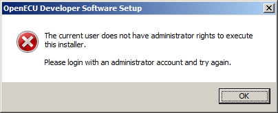
The installer requires that the user has administrative rights to make changes on the computer. If a user without rights is trying to execute the installer a dialog box will be displayed and the installation stops. Login with an administrator account or contact your network administrator and try again.
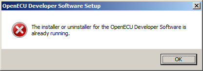
If a version of an OpenECU installer is already running, a dialog box will appear saying so. Select OK (which stops the current installer) and change to the other OpenECU installer to continue.
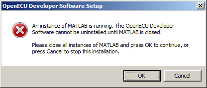
If a version of MATLAB is running, a dialog box will appear saying so. Quit all instances of MATLAB, then select OK to continue installation.
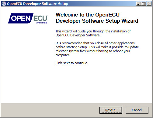
The installation process starts with an introduction. Select Next to continue.
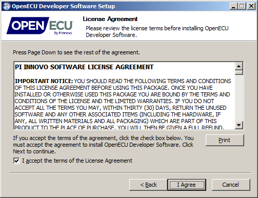
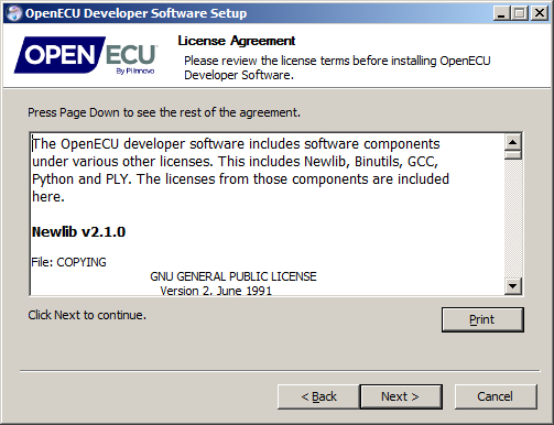
The next windows to appear present the license agreement for using OpenECU developer software and related software. Read the license agreements and if acceptable, select I accept the terms of the License Agreement and then Next. If not acceptable, do not install the software.
The next window to appear provides a number of components that can be installed or patched.
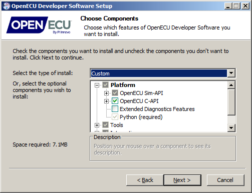
The following table breaks out each of the components:
Table 2.2. Install components
| Component | Required | Installed by default | Description |
|---|---|---|---|
| Platform | Yes | Yes | A selection of packages to install, including the C-API and Sim-API components. |
| OpenECU Sim-API | Yes | Yes | Install the Simulink interface to OpenECU, documentation and support packages. |
| Blockset | Yes | Yes | Install the OpenECU blockset. |
| Sim-API Manuals (HTML) | (optional) | Yes | Install the OpenECU blockset, ECU Technical Specifications and other documentation in HTML format. |
| Sim-API Manuals (PDF) | (optional) | Yes | Install the OpenECU blockset, ECU Technical Specifications and other documentation in PDF format. |
| Sim-API Examples | (optional) | Yes | Install some examples of how to use the OpenECU blockset. |
| OpenECU C-API | Yes | Yes | Install the OpenECU C-API files and libraries. |
| C-API | Yes | Yes | Install the C interface to OpenECU, documentation and support packages. |
| C-API Manuals (HTML) | (optional) | Yes | Install the OpenECU C-API User Guide, ECU Technical Specifications and other documentation in HTML format. |
| C-API Manuals (PDF) | (optional) | Yes | Install the OpenECU C-API User Guide, ECU Technical Specifications and other documentation in PDF format. |
| C-API Examples | (optional) | Yes | Install some examples of how to use the OpenECU C interface. |
| Extended Diagnostics Features | (optional) | No | Install the On-Board Diagnostic (OBD) library. This library is available at extra cost. |
| Python | Yes | Yes | Install the Python application. This application is used to provide build support when generating and compiling the model source code. |
| Tools | (optional) | No | Installs additional OpenECU tools. |
| GCC | (optional) | Yes | Installs the GNU Compiler Collection (v4.7.3) and related tools for OpenECU targets. |
| lmadmin installer | (optional) | No | Installs the installers for the lmadmin license server from flexera. |
| FreeCCP | (optional) | No | Installs the FreeCCP programming tool (note that this tool is provided without support or warranty). |
| Integration | (optional) | Yes | Options to have the OpenECU installer integrate OpenECU with third party tools, like MATLAB and INCA. |
| MATLAB Integration | (optional) | Yes | During installation, the OpenECU blockset is integrated into MATLAB's PATH. |
| INCA-ProF Integration | (optional) | No | During installation, INCA-ProF is update to understand how to program an OpenECU. |
| Start Menu Shortcuts | (optional) | Yes | During installation, the Window's Start menu is updated to include shortcuts to installed components. |
Adjust the component selection as required (especially if you require the installer to update an installed copy of ETAS INCA) and select the Next button.
The next window asks for a destination path to be specified. By default, the installer presents a path to your local drive.
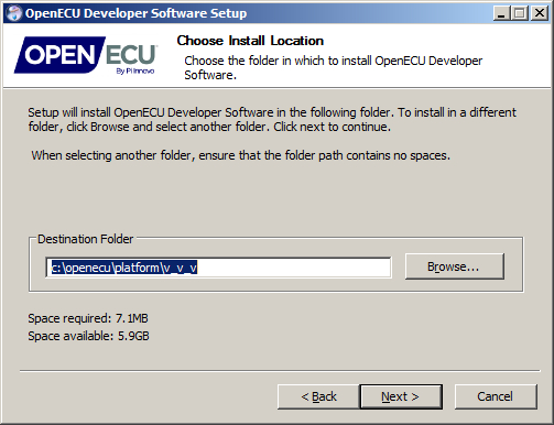
Warning
If the default path is changed, ensure that only digits, upper and lower case letters
and the _ character are used to specify directory names. An installation
path that includes any space characters will cause problems later on.
If the MATLAB integration component was selected, the next window presented provides a list of installed and compatible versions of MATLAB. The example here shows that OpenECU should be integrated with MATLAB R2008b.
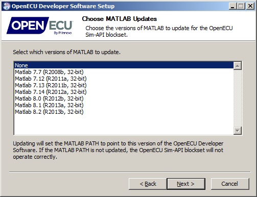
Select which versions of MATLAB will be used with OpenECU and select the Next button. If no version should be updated select None.
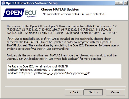
If no compatible versions of MATLAB were found, the next window presents the command to run to add OpenECU to MATLAB (more details given in Section 2.5.4, “MATLAB”).
If the INCA-ProF integration component was selected, the next window presented provides a list of installed versions of INCA.
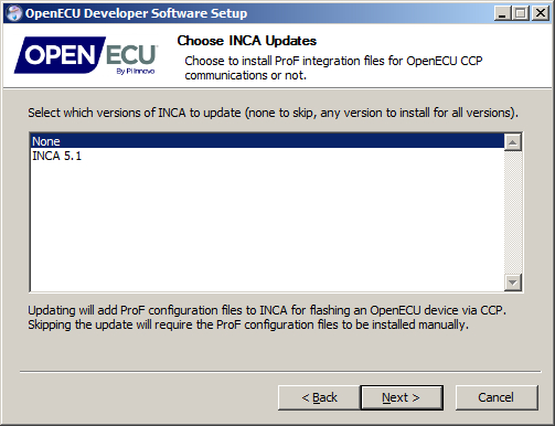
Select which versions of INCA will be used with OpenECU and select the Next button. If no version should be updated select None.
Note
If any version of INCA is selected, then the installer will add OpenECU integration to all versions of INCA. This is simply a consequence of the way INCA works.
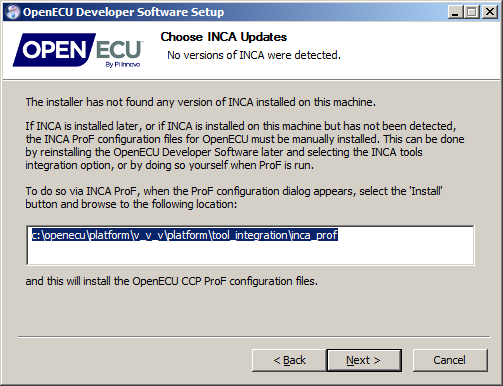
If no versions of INCA were found, the next window presents details on how to achieve this by hand (more details given in Section 2.5.7, “ETAS INCA calibration tool”). The instructions should be carried out when INCA-ProF runs.
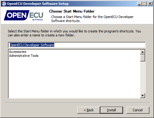
If the Start Menu Shortcuts component was selected, then the next window presented asks the user to select where in the Start menu the OpenECU items will be added. During install, the installer adds short cuts to the documentation components selected and to the OpenECU uninstall application.
Once installation has completed, the user is provided an option to read the getting started guide, the release notes and to visit the OpenECU web site.
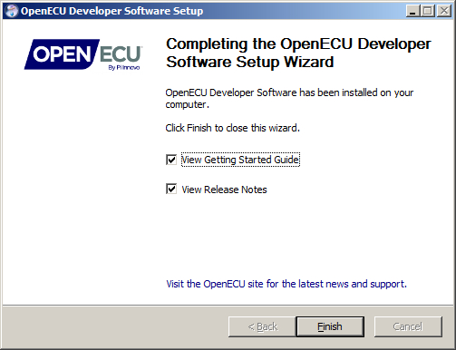
Getting started guide
If you are a first time user of OpenECU, it is strongly recommend following the getting started guide, which covers what tools can be used with OpenECU and how to configure OpenECU and those tools to work together.
Release notes
If you are installing a new version of OpenECU, it is strongly recommended that you read the release notes. Some releases of OpenECU change the functionality of features which may have an impact on existing applications.
Machine identification generated by the license tools is required to activate an OpenECU platform license.
This section is a quick setup guide to get OpenECU working with your license. Consult the license administration guide for more information on license management and administration. This document is provided with the installation at "[install path]\doc_user\License-Administration-Guide.pdf".
To setup a floating license, the vender daemon will have to be run on the designated license server as well as have a license file on that machine. This section describes setting up the vendor daemon for a floating license.
After installing the platform, copy the files in "[install path]\tools\flexera\i86_n3\" to your designated license server. On that machine, run lmtools.exe.
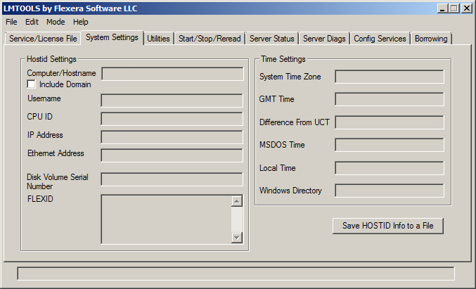
Select the "System Settings tab", check "Include Domain", and press the button that says "Save HOSTID Info to a File".
Email the file to Pi Innovo with the purchase order. When the purchase is complete, Pi will send you a valid license file. (Or if you have already completed the purchase, reply to the welcome email with this information)
It is recommended that lmadmin license server manager be used to serve licenses. Run the lmadmin installer to install the software. Once the installation is complete, copy the vender daemon, openecu.exe, into the install directory, "C:\Program Files (x86)\FlexNet Publisher License Server Manager\".
Start the license server manager. You can then use the web interface to upload the license file and start serving your license.
Note
If a license has not yet been purchased, email the file to Pi Innovo with the purchase order. When the purchase is complete, Pi will send a valid license file. If the purchace has already been completed, reply to the welcome email with this information.
It is recommended that lmadmin license server manager be used to serve licenses. Run the lmadmin installer and start the license server manager. The web interface can then be used to upload the license file and start serving your license.
Note
Details on installing and using the lmadmin tool are in Chapter 9 of the License Administration Guide, "[install path]\doc_user\License-Administration-Guide.pdf".
Note
lmgrd is also provided with the platform as an alternative to lmadmin; consult Chapter 10 of the License Administration guide for details on its use.
To setup a node-locked license, a license file must be placed on the development machine.
After installing the platform, run the file: '[install path]\tools\flexera\i86_n3\lmtools.exe'
Select the "System Settings tab", check "Include Domain", and Press the button that says "Save HOSTID Info to a File" (see screen shot above)
Email the file to Pi Innovo with the purchase order. When the purchase is complete, Pi will send you a valid license file. (Or if you have already completed the purchase, reply to the welcome email with this information) If a license has not yet been purchased, email the file to Pi Innovo with the purchase order. When the purchase is complete, Pi will send a valid license file. If the purchace has already been completed, reply to the welcome email with this information.
Copy the file to the directory "C:\openecu" or update the OPENECU_LICENSE_FILE environment variable with the location of your file.
Navigate through the Windows All Programs Start Menu shortcuts and find the OpenECU Developer Software directory. Select the version of OpenECU to remove and run the uninstaller.
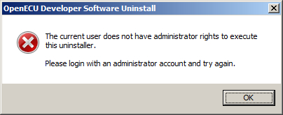
The uninstaller requires that the user has administrative rights to make changes on the computer. If a user without rights is trying to execute the uninstaller a dialog box will be displayed and the uninstaller stops. Login with an administrator account or contact your network administrator and try again.
If a version of an OpenECU uninstaller is already running, a dialog box will appear saying so. Select OK and change to the other OpenECU uninstaller to continue.

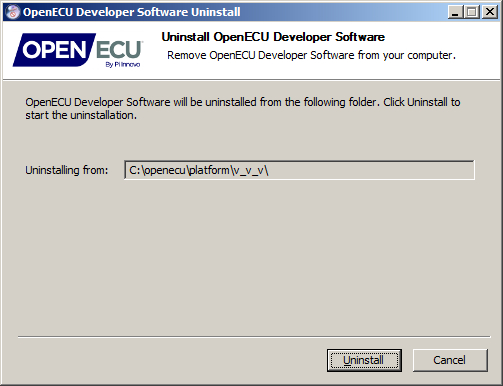
The uninstaller presents the location of the previous install to remove. Select the Uninstall button to continue (this will remove that version of OpenECU) or select the Cancel button to stop the uninstall.
When uninstalling, if this version of OpenECU is present in MATLAB's
PATH, then the uninstaller will not remove the reference.
Next time MATLAB is started, it will try to gain access to the
deleted OpenECU directory and will raise an error. When this occurs, manually remove
the OpenECU directories by selecting MATLAB's menu option File->Set Path....
Note
The OpenECU uninstaller does not remove the INCA-ProF configuration files for CCP.
The installer integrates the OpenECU package with Windows 10 by modifying the Start menu, by modifying some registry items and by copying files to a local drive.
OpenECU developer software may not function correctly on encrypted drives. OpenECU developer software must be able to create files on the host file system. If using an encrypted drive, be sure that permission settings will allow OpenECU to create files. Pi Innovo cannot provide support for issues with encrypted drives.
The installer integrates the OpenECU package with Windows 7 SP1 by modifying the Start menu, by modifying some registry items and by copying files to a local drive.
OpenECU developer software may not function correctly on encrypted drives. OpenECU developer software must be able to create files on the host file system. If using an encrypted drive, be sure that permission settings will allow OpenECU to create files. Pi Innovo cannot provide support for issues with encrypted drives.
The installer integrates the OpenECU package with Windows XP SP3 by modifying the Start menu, by modifying some registry items and by copying files to a local drive.
OpenECU developer software may not function correctly on encrypted drives. OpenECU developer software must be able to create files on the host file system. If using an encrypted drive, be sure that permission settings will allow OpenECU to create files. Pi Innovo cannot provide support for issues with encrypted drives.
The installer integrates the OpenECU package with MATLAB and Simulink. However, if for any reason the installer could not find an installed version of MATLAB, the user can manually integrate the OpenECU blockset by issuing the following MATLAB commands:
addpath '[install path]\openecu'
addpath '[install path]\openecu\rtw\c\openecu_ert\code_templates'
addpath '[install path]\openecu\rtw\c\openecu_ert'
addpath '[install path]\openecu\rtw\c\openecu_grt'
addpath '[install path]\openecu\rtw\c\openecu_grt_rsim'
addpath '[install path]\openecu\mex_r<release>'
addpath '[install path]\openecu\mfile'
addpath '[install path]\openecu\model'
Note
where the text [install path] is replaced by the installed
location of the OpenECU blockset, e.g., c:\openecu\platform\1_9_2;
and the text <release> is replaced with the major
version of MATLAB (e.g., 2013b or 2013b_64
for 64-bit versions of MATLAB).
Once the path has been added, the user can check the OpenECU version by issuing the following MATLAB command:
ver openecu
A correct response will look something like:
OpenECU Blockset (Pi Innovo) Version <number> <date>
If nothing is printed, or an error message is returned, then the path specified by
the addpath command was incorrect and should be changed.
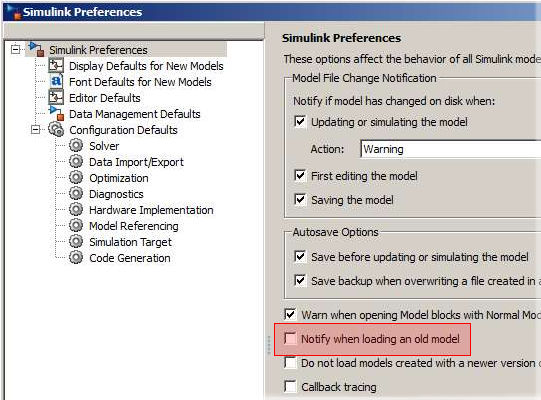
Open: When loading an OpenECU model, Simulink may issue warnings similar to this:
Warning: Model '...' was last saved using an old version (...) of Simulink.
For advice on upgrading this model to the current version of Simulink, see
the Upgrade Advisor.
> In oe_test_required_platform_vers at 26
  In oe_make_rtw_hook at 153
  In openecu_make_rtw_hook at 6
  In general\private\openmdl at 13
  In open at 159
  In uiopen at 167
Workaround: Turn off the Notify when loading an old model option in Simulink's preferences:
Unlike some other calibration tools, during installation there is nothing special to be done when integrating PiSnoop and OpenECU.
Unlike some other calibration tools, during installation there is nothing special to be done when integrating Vision and OpenECU.
Open: integration issues with OpenECU while creating a Vision VST (strategy) file.
There have been integration issues between Vision and OpenECU, when the user requests a build create a Vision VST (strategy) file. If OpenECU cannot create a strategy file, then it may be necessary to register the COM interface for Vision by running the
RegisterCOMInterface.batfile included in the install of ATI Vision.Open: does not operate correctly with encrypted hard drives.
There have been reports of Vision interacting poorly with encrypted hard drives. At the moment, it is not clear what the problem might be. On one occasion, Pi worked with ATI and a customer and determined a work around that is not understood. The work around was to rename the executable file for Vision to something longer than 11 characters.
Open: some earlier versions do not support CCP seed/key correctly.
ATI Vision 2006 (v3.2) is the earliest version for which CCP seed/key security has been validated by Pi Innovo. Earlier versions may support CCP seed/key security (see the relevant Vision documentation) but bugs in the CCP implementation on various targets are known to exist. ATI have recommended that earlier versions should not be used, or should be used with caution.
The installer integrates the OpenECU package with the ETAS INCA tool. However, if for any reason the installer could not find an installed version of INCA, the user can manually integrate the necessary ProF component.
The INCA-ProF tool programs OpenECU over CCP using a set of configuration files. In order to manually integrate these configuration files, the user must run INCA, open an experiment, select manage memory then flash programming.
The user is then presented with a dialog box to browse ProF configurations, or a ProF settings dialog box (in which case the user must select Configure...).
With the browse ProF configurations dialog box, select the "Install..." button and browse to the install location of OpenECU:
[install path]\tools_integration\inca_prof
and select OK. This will have manually installed the INCA-ProF configuration file for OpenECU.
Note
If manually integrating and the ProF files cannot be found in the location above, then re-run the OpenECU installer and select the Integration -> INCA-ProF Integration option and try again.
Unlike some other calibration tools, during installation there is nothing special to be done when integrating CANape and OpenECU.
The Wind River (Diab) compiler 5.5.1.0 can be installed by running the file
setup.exe from the supplied media — several
options will be presented during the compiler install and the following
responses should be used:
On Choose your Activation Type window, select one of the following options:
Permanent activation if you have been assigned with a license file from Wind River, usually named
WRSLicence.lic. The full path should point to the license file.Temporary activation if you wish to use the Wind River (Diab) compiler on an evaluation basis, or temporary basis until a permanent license is provided.
A reboot may be required to complete installation of the Wind River (Diab) compiler.
If using one version of the Wind River (Diab) compiler, either setup the
OPENECU_DIAB_5_5_1_0environment variable as described in the next point, or adjust Window's system path to include the absolute path to the compiler'sbindirectory.If using more than one version of the Wind River (Diab) compiler (for instance, when you are using two or more versions of OpenECU which require different versions of the Wind River (Diab) compiler), the environment variable
OPENECU_DIAB_5_5_1_0must be set to the absolute path to the compiler'sbindirectory. This macro must terminate in a “\” and must use the DOS 8.3 short naming convention.E.g.,
D:\Progra~1\diab\5_5_1_0\win32\bin\Note
After setting the environment variable, MATLAB may need to be restarted to pick up the new setting. If in doubt, issue the:
oe_check_compiler
command at MATLAB's prompt to check that the environment variable is correctly setup and the compiler is available.
Closed: incorrect generation of object code for “float <= float” comparisons.
The compiler incorrectly generates object code for “float <= float” comparisons, turning the comparison into “float > float”. This issue has been resolved by removing the
-Xieee754-pedanticcommand line option to the compiler command line option to the build configuration files.
Open: incorrect generation of object code for long C functions.
The compiler incorrectly generates jump instructions in the object code if the jump destination address differs from the address of the jump instruction by more than 15 bits (signed). No warning or error is generated by the compiler. The result is a model which does not behave as expected when run on target (usually the ECU appears as if it is continually resetting).
To alert the user to this risk, an OpenECU build checks for large functions and issues a warning message if any are found. The message takes the form:
Warning: Function foo is very large (0x000abcdef).
The generated object code may be susceptible to a known compiler defect.
Refer to the OpenECU user guide for further details.
Workaround (Simulink): RTW generates just a couple of C functions for the model, rather than splitting major sub-systems into their own functions. Hence those functions can become large enough to hit this compiler problem if the model is large. This can be avoided by applying the atomic subsystem option to key subsystems in the model. RTW generates a different C function for each atomic subsystem, where each resulting function corresponds to just part of what would have been one large function. You should split any large model up like this to avoid any one C function becoming large enough to hit this compiler problem.
Open: generation of non-existent labels.
The compiler can generate non-existent labels such as ".L1013" when compiling code involving large structures, such as those generated by TargetLink. The code then fails to link because the labels are not defined. This has not yet been seen with Simulink builds but it may possibly be seen in future.
Workaround: if this problem is encountered, a patched version of the compiler is available from Wind River for customers who have compiler support (quote service request 1054126).
Open: incorrect rounding on conversion from float to integer types.
The compiler rounds values when converting from floating point to integer, e.g. from "float" to "signed long" (in terms of native types, otherwise known as F32 and S32 in the OpenECU environment). For example, 3.6 as a float is rounded to 4 as an integer, but the C standard requires that the fractional part is truncated, so a converted value of 3 would be correct. Similarly -3.6 is rounded to -4 instead of being truncated to -3. This defect is fixed in version 5.8.0.0 of the compiler.
Workaround: if this problem is encountered, a patched version of the compiler is available from Wind River for customers who have compiler support (quote service request 864470).
Closed: Can't use Simulink look up blocks
There has been a known issue which restricts the compiler to use Simulink lookup block. When using Simulink lookup blocks, the Diab compiler would stop compilation with this error message:
'[model-name].c', line [line-num]: warning (dcc:1792):
                                   trying to assign 'ptr to volatile' to 'ptr'
This has now been fixed, see F-CR 13325 in the release notes.
Closed: compiling the main model file can take a long time.
Small models compile in a short period of time, but once the code presented to the compiler exceeds a limit, the compiler takes a long time to compile the main model file (
model-name.c).Workaround: the compiler sets aside an amount of memory for the compilation phase and if the size of the model code exceeds the limit, the compilation slows down. This can be avoided by increasing the size of the compiler's buffer using a command line option. Add the
pcomp_CompileOptionsblock to the model, set the mode parameter toAdd to optionsand set the compiler options parameter to-Xparse-size=100000. If the compilation is still slow, increase the option value further.
The Wind River (Diab) compiler 5.8.0.0 can be installed by running the file
setup.exe from the supplied media — several
options will be presented during the compiler install and the following
responses should be used:
Follow the guidance given in Section 2.5.9, “Wind River (Diab) C Compiler v5.5.1.0”.
If using a single version of the Wind River (Diab) compiler, either setup the
OPENECU_DIAB_5_8environment variable as described in the next point, or adjust Window's system path to include the absolute path to the compiler'sbindirectory.If using multiple versions of the Wind River (Diab) compiler (for instance, when you are using two or more versions of OpenECU which require different versions of the Wind River (Diab) compiler), the environment variable
OPENECU_DIAB_5_8must be set to the absolute path to the compiler'sbindirectory. This macro must terminate in a “\” and must use the DOS 8.3 short naming convention.E.g.,
D:\Progra~1\diab\5_8_0_0\win32\bin\Note
After setting the environment variable, MATLAB may need to be restarted to pick up the new setting. If in doubt, issue the:
oe_check_compiler
command at MATLAB's prompt to check that the environment variable is correctly setup and the compiler is available.
Closed: Can't use Simulink look up blocks
There has been a known issue which restricts the compiler to use Simulink lookup block. When using Simulink lookup blocks, the Diab compiler would stop compilation with this error message:
'[model-name].c', line [line-num]: warning (dcc:1792):
                                   trying to assign 'ptr to volatile' to 'ptr'
This has now been fixed, see F-CR 13325 in the release notes.
The Wind River (Diab) compiler 5.9.0.0 can be installed by running the file
setup.exe from the supplied media — several
options will be presented during the compiler install and the following
responses should be used:
Follow the guidance given in Section 2.5.9, “Wind River (Diab) C Compiler v5.5.1.0”.
If using a single version of the Wind River (Diab) compiler, either setup the
OPENECU_DIAB_5_9environment variable as described in the next point, or adjust Window's system path to include the absolute path to the compiler'sbindirectory.If using multiple versions of the Wind River (Diab) compiler (for instance, when you are using two or more versions of OpenECU which require different versions of the Wind River (Diab) compiler), the environment variable
OPENECU_DIAB_5_9must be set to the absolute path to the compiler'sbindirectory. This macro must terminate in a “\” and must use the DOS 8.3 short naming convention.E.g.,
D:\Progra~1\diab\5_9_0_0\win32\bin\Note
After setting the environment variable, MATLAB may need to be restarted to pick up the new setting. If in doubt, issue the:
oe_check_compiler
command at MATLAB's prompt to check that the environment variable is correctly setup and the compiler is available.
Closed: Can't use Simulink look up blocks
There has been a known issue which restricts the compiler to use Simulink lookup block. When using Simulink lookup blocks, the Diab compiler would stop compilation with this error message:
'[model-name].c', line [line-num]: warning (dcc:1792):
                                   trying to assign 'ptr to volatile' to 'ptr'
This has now been fixed, see F-CR 13325 in the release notes.
Open: Error message 0169
The Diab 5.9.0.0 compiler generates object files that cause the Diab ddump command to generate the following error message during an application build.
Error 0169 at offset NNNNNNNN: Unexpected EOF.
The error appears to be benign and can be ignored. Currently, there is no known workaround.
GCC, also known as the GNU Compiler Collection, is a free compiler system produced by the GNU Project supporting various programming languages. The Free Software Foundation (FSF) distributes GCC under the GNU Public License (GNU GPL). GCC has been adopted as the standard compiler by most modern Unix-like computer operating system and has also been ported to a wide variety of processor architectures and is available for most embedded platforms.
GCC is used with permission under the GPL Version 3. If GCC is installed with OpenECU,
the license file can be found in the [install path]\tools\gcc\ppc\docs
directory of the OpenECU install. If desired, a copy of the GCC source code can be found
and downloaded from the Pi Innovo website.
Support for GCC is currently in beta and as such, the user may run into issues which can cause an application to fail to build or run correctly on target. Listed below are a set of known issues when building an application using GCC. See Appendix K, Contact information for details on how to get in contact with OpenECU support if support is needed for using GCC.
GCC is not recommended for production programs at this time.
GCC is an optional component in the OpenECU installation and is installed by default.
Open: Applications built with the GCC compiler do not support the diagnostics feature at this time. Applications using the diagnostics feature will not compile.
Information: compiler warnings when using Simulink look up blocks.
When building a model that uses Simulink look up blocks, the compiler will emit diagnostic messages similar to the following. These can be ignored.
[file-line]: warning: passing argument 2 of '[lookup function]'
                      discards 'volatile' qualifier from pointer target type
                      [enabled by default]
[file-line]: note: expected 'const real_T *' but argument is of type
                   'const volatile real_T *'
Information: GCC only supports non-VLE code. Therefore, the compiled code will be larger. In general, GCC applications will be about 50% bigger than code generated by Diab.
Information: The GNU linker locates data slightly differently than the Diab linker in the final images. RAM and Flash memory utilization may be different for the same application compiled by different compilers.
Open: Applications built with GCC in general exhibit higher CPU loading than applications build with Diab.
Python is general purpose, high level interpreted programming language, distributed
under the PSF license which allows use in non open-source commercial applications.
The license can be found in the [install path]\tools\python\license.txt
file.
Open: When using OpenECU, Python may raise an error about an incorrect DLL. For example, “The procedure entry point for X could not be located in the dynamic link library py[name].dll”. This can occur if another application installed on the same machine as OpenECU has also installed Python (for instance, dSpace ControlDesk).
Workaround: Browse to the Windows system directory. Depending on the version of Windows, this will be one of:
c:\windows\system32; or
c:\windows\syswow64
Locate the DLL referred to in the error message. The file will start with the characters “py” and end with “.dll”. Group all Python DLLs and move them to a temporary location, then restart OpenECU.
Temporarily moving DLLs will cause the other application to run incorrectly (and if DLLs unrelated to Python are inadvertantly moved, then the applications that rely on those DLLs may not run correctly). You can resolve this by returning the moved DLLs to their original location, or possibly moving the DLLs to the location of the installed applications.
Note
The OpenECU installation of Python does not write files to the Windows directories, or modify global registry entries relating to Python. As such, the OpenECU installation of Python is entirely local to OpenECU and will not affect other packages.
This chapter gives you a quick introduction to building and simulating models, and an introduction to programming the OpenECU device.
The step1 exercise in Section 3.3, “Exercise — Step 1” describes how to incorporate the Pi OpenECU blocks into your own Simulink designs, and how to test and calibrate your models on the ECU. The exercise requires the following resources:
a working knowledge of MATLAB and Simulink;
a complete installation of Pi's OpenECU Simulink blocks: see Chapter 2, Installation;
a complete installation of supporting tools (e.g., compiler, calibration tool, etc.: see Chapter 2, Installation and Appendix B, Supporting tools);
The installation of OpenECU comes with a number of explanatory examples of how to use OpenECU, including a completed step1 example (see Section 3.3, “Exercise — Step 1”) configured for each supported ECU.
These examples can be accessed through MATLAB's launch pad or start menu. For instance, select the launch pad, browse to the OpenECU selection and click on examples.
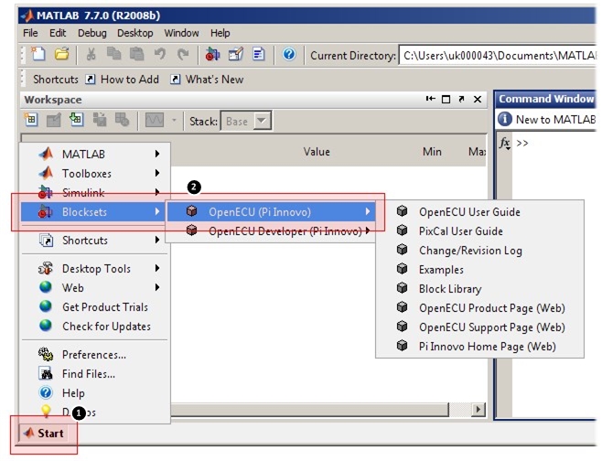
Or with later versions of MATLAB, run the following at MATLAB's command prompt.
oe_examplesThe examples model will open with a series of subsystems:

Open the subsystem of interest and a series of blocks representing the example for at least one ECU will appear.
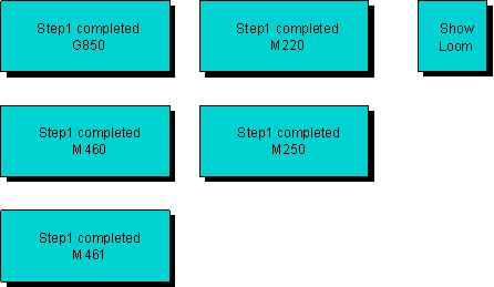
For each example there is a block that details the loom, or how to connect OpenECU pins to other devices to make the example work. An example or loom specification can be viewed by double clicking or opening the appropriate block.
The available examples are:
- CANdb demo
An example which shows how the CANdb blocks (pcx_CANReceiveMessage and pcx_CANTransmitMessage) of OpenECU can be utilised.
- Extended diagnostics
An example which shows how to use the extended diagnostics library to link diagnostic trouble code, freeze frame, in-use performance ratio and J1939 communication blocks together.
- Fixed Angular demo
An example which shows how the angular functionality of OpenECU can be used to track engine position via crank and cam wheel inputs, and produce fixed pulses for injectors and ignition coils.
- Multi-rate demo
An example which shows how to transfer data between two portions of a model which run at different rates. Simulink has specific rules about how to connect different rates this and the example shows how this can be achieved.
- NVM demo
An example which shows how the Adaptive Parameters (NVM) functionality of OpenECU should be used. This includes two methods accumulating data to be stored (incremental (2d map) or direct (array)) and the additional required blocks to commit the adapted values to NVM.
- Step1 completed
A set of completed step1 models for each ECU is available for reference (useful for just trying OpenECU without the need to follow the detailed steps presented later).
- Two pot. demo
A similar example to step1 that shows a simple combination of input reading, processing and output driving.
- Two pot. demo with S-Function
An example with the same functionality as the Two pot. demo but with some of the internal signal processing being achieved by using an S-Function.
Most examples can be run on any ECU. If you find an example but there isn't a corresponding model for your ECU, change the ECU target as described in by the put_Identification block and then adjust any I/O pin selections. If you need a hand, please contact us.
This exercise describes how to build, simulate and test a model that monitors a temperature and activates a warning lamp if a temperature threshold is breached. The model uses a single analogue input to measure the temperature, and a single PWM output to activate a 5 volt warning lamp.
The exercise requires the OpenECU to be connected to various devices and components as pictured in Figure 3.2, “Quick start loom”.
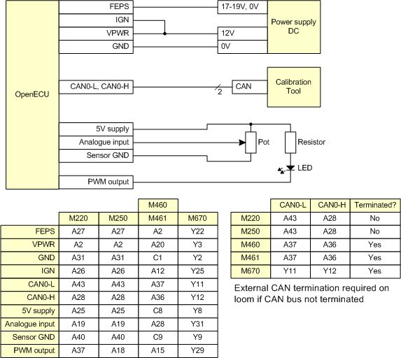
By following the instructions below, you will complete the model design, test the simulation, create compiled C code and test the model running on the ECU.
Before any engineering project reaches the design and modelling stage, several detailed planning stages should be carried out to define suitable functional requirements and specifications. Once you have a detailed target for your design, you can then start to create and model it. Many engineers prefer to use pen and paper, but it's equally acceptable these days to develop your design directly in modelling packages such as MATLAB and Simulink.
In this example, we have designed and partially modelled the system for you — you need only finish the modelling process as described below.
To create the model:
Create an empty model
Create an empty directory somewhere to store the step1 model. Start up MATLAB/Simulink and change to that directory. Read off the part and issue numbers from the label on your ECU. The part number is the text string beginning '01T-'. The issue number appears immediately afterwards: it is the number before the 'm'. For example, the label on an M250 module might read:
Part No. 01T-068276-000 2m1In this example, the part number is '01T-068276-000' and the issue number is 2. Note that some part do not include the last three characters. Issue the following command at MATLAB's command prompt:
oe_create_model('step1',
                'dd',       'stp',
                'template', 'minimal',
                'part',     '01T-068276-000',
                'issue',    2)
This will create an OpenECU model named 'step1' with appropriate model settings as well as a basic build list and a data dictionary using the prefix 'stp'. Replace the text string '01T-068276-000' with the part number for your ECU, and the number 2 with the issue number for your ECU. For more information issue the following command at MATLAB's command prompt:
help oe_create_model
If your ECU part number does not have the final three characters, just enter what is there, for example:
oe_create_model('step1',
                'dd',       'stp',
                'template', 'minimal',
                'part',     '01T-068276',
                'issue',    2)
A new model with 'minimal' template has opened containing a single block called put_Identification and while the model was opening, some additional text was printed to the MATLAB command window.
Obtaining workspace data from each feature data dictionary...
Workspace variables loaded
Populate the model
Open the Library browser window and select the blocks that you will use in your model. These blocks are:
from the Source list: Ground;
from the Sink list: Terminator;
from the Math list: Constant, Relational Operator;
from the Pi OpenECU, Input Drivers list: Analogue Input;
from the Pi OpenECU, Output Drivers list: PWM Output;
from the Pi OpenECU, CAN Drivers list: CAN Configuration;
from the Pi OpenECU, Utilities list: Identification, CCP Configuration.
Change the operation of the Relational Operator block to greater-than (>).
Connect the blocks
Connect the blocks together as shown in Figure 3.3, “Connected quick start model” (note that the text in gray is commentary for this manual and need not be entered in your model):
Note
The analogue input needs to be connected to ground and the PWM output needs to be terminated to prevent Simulink from reporting an Unconnected Input error when the simulation is run. The grounded inputs and outputs to and from your system only provide simulated inputs and outputs when running in Simulink. When running on the target ECU, these grounded inputs and outputs are ignored and the blocks read sensors and drive actuators.
Save the model
Save the model. You now have a partially complete graphical model of your design.
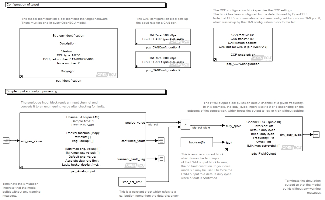
We still need to incorporate some design variables and parameters in some of the blocks and interconnecting wires or signals in our model. By naming things, we can use the calibration tool to set or inspect their values when we test the working system running on the ECU.
While designing and running the model, and later testing it with the calibration tool, it is very useful to be able to interactively display and set the values that are present on parts of the model. You can do this by assigning names to a signal or input at the modelling stage, and then display or set the value associated with that variable as the model simulation is running.
Variables must be named according to a system described in full in Section 5.2.5, “Naming rules”. This system helps you to identify what type of information the variable holds, and where it is initialised and used — very helpful in tracking down any design faults. Note that calibratable variables of this type can only be changed on-the-fly with the development ECU (i.e. not with the fleet ECU, which requires programming of its memory to change any variable values).
We will use two signal variables in our design:
stp_ectThis is the value of the temperature that is output from the Analogue Input block, representing the temperature of the engine in degrees Centigrade;
stp_ect_stateThis is the result of the relational operator that calculates whether the engine temperature is greater than the threshold temperature. It is 1 when the threshold is breached, and 0 otherwise.
Label the signals on either side of the Relational Operator block as follows:
To assign a name to a signal:
double-click on the appropriate signal and a text box will open beneath it;
type in the variable name, then click outside the box to complete.
We will also use a variable so that we can change the threshold temperature while the simulation is running. Note that calibratable variables of this type can only be changed on-the-fly in the ECU with the development ECU (i.e. not with the fleet ECU, which requires programming of its memory to change any variable values).
The variable to set up is stpc_ect_limit
— the threshold temperature (in degrees Centigrade) which
defines the temperature above which our warning light will switch on.
To set this variable:
double-click on the Constant block that leads into the lower of the two Relational Operator inputs. A dialogue box appears.
click in the Value box, and instead of entering a numerical value, enter the variable name
stpc_ect_limit. This now references a MATLAB workspace variable (which we will create further on).
You will also need to set a single constant used in the model:
double-click the Constant block that leads into the fault_value inport of the PWM Output block. A dialogue box appears.
click in the Value box and enter
boolean(0). This instructs the PWM Output block that there are no faults in the system.
Before we can run the model simulation, each Simulink block requires a number of parameters that define initial conditions, sample rates, and various other dynamic properties of the model.
Block parameters are set by double-clicking on the block and entering appropriate values in the various parameter fields that are displayed. Some parameters may only take on certain values, in which case the text field is replaced by a drop-down list, from which you can select the appropriate value.
The parameters dialogue box for the Model Identification looks like this:
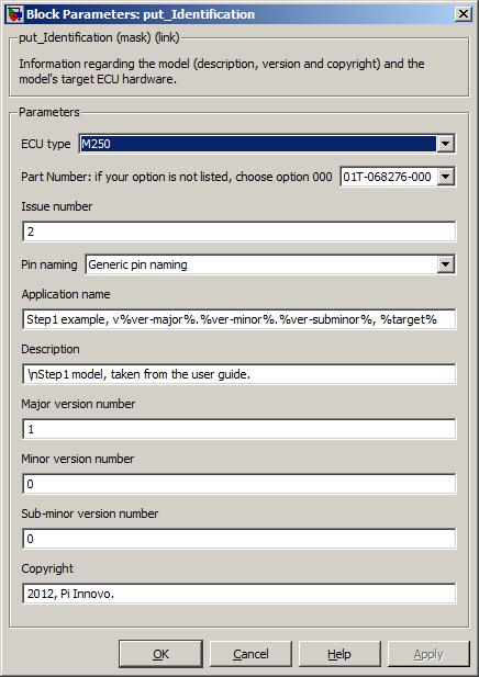
Set the block mask parameters as the figure shows. A full description of the block mask parameters is given later on Section 6.1.63, “Model identification (put_Identification)”, but a summary of the items and their meaning is given here for this example.
Table 3.1. Step1 - model identification block parameters
| Parameter | Description | Set to |
|---|---|---|
| ECU type | Identifies the name of the type of ECU. | (already set by running the oe_create_model
command) |
| Part Number | Identifies the hardware part number of the ECU. | (already set by running the oe_create_model
command) |
| Issue number | Identifies the issue number of the ECU. | (already set by running the oe_create_model
command) |
| Pin naming | Specifies the naming given to each blocks channel or pin selection. | Generic pin naming |
| Application name | Specifies a name for the application/model. Although this parameter has no functional effect on the model, it is used when generating the model ASAP2 file and can be retrieved over CCP using the EXCHANGE-ID message. | Step1 example, v%ver-major%.%ver-minor%.%ver-subminor%, %target% |
| Description | Specifies a description of the model (this parameter has no functional effect on the model). | Step1 model from OpenECU manual. |
| Major version number | Specifies the major version number of the model. This value can be read over CCP by a ASAP2 compliant tool and is useful to determine if the target hardware is running the correct version of the model. | 1 |
| Minor version number | Specifies the minor version number of the model. This value can be read over CCP by a ASAP2 compliant tool and is useful to determine if the target hardware is running the correct version of the model. | 0 |
| Sub-minor version number | Specifies the minor version number of the model. This value can be read over CCP by a ASAP2 compliant tool and is useful to determine if the target hardware is running the correct version of the model. | 0 |
| Copyright | Specifies a copyright for the model (this parameter has no functional effect on the model). | 2012. |
Note
It is essential to include a put_Identification block in all OpenECU top level models. If this block is not present, the model will not work as documented.
The parameters dialogue box for the CAN Configuration looks like this:
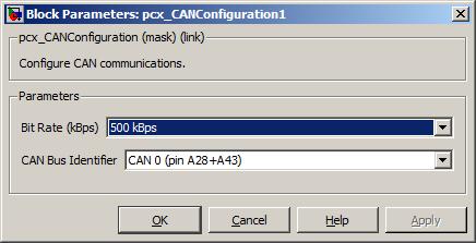
Set the block mask parameters as the figure shows. A full description of the block mask parameters is given later in Section 6.1.13, “CAN configuration (pcx_CANConfiguration)”, but a summary of the items and their meaning is given here for this example.
Table 3.2. Step1 - CAN configuration block parameters
| Parameter | Description | Set to |
|---|---|---|
| Bit rate | The bit rate (or baud rate) of the CAN bus. | 500 kBps |
| CAN bus identifier | Which CAN bus the configuration applies to. | CAN 0 |
The parameters dialogue box for the CCP Configuration looks like this:
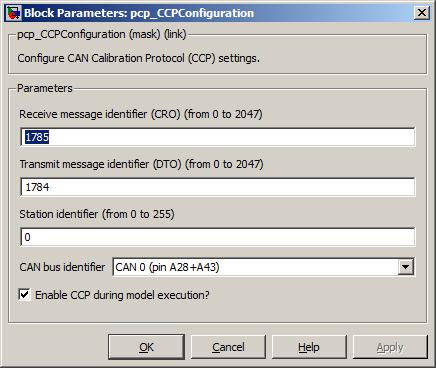
Set the block mask parameters as the figure shows. A full description of the block mask parameters is given later in Section 6.1.19, “CCP configuration (pcp_CCPConfiguration)”, but a summary of the items and their meaning is given here for this example.
Table 3.3. Step1 - CCP configuration block parameters
| Parameter | Description | Set to |
|---|---|---|
| Receive message identifier | A unique standard CAN message identifier for CCP CRO messages. This is the CAN identifier used to talk to the OpenECU device. For this example, we'll use the default value. | 1785 |
| Transmit message identifier | A unique standard CAN message identifier for CCP DTO messages. This is the CAN identifier used to talk from the OpenECU device. For this example, we'll use the default value. | 1784 |
| Station address | The station address for CCP sessions. OpenECU will only communicate using CCP if a session is opened using this station address. For this example, we'll use the default value. | 0 |
| CAN bus identifier | Which CAN bus CCP communications will occur on. Previously, we configured CAN 0 to run at 500 kBps, so we'll use CAN 0 for CCP communications. | CAN 0 |
| Enable CCP during model execution? | Whether to communicate using CCP when the model is
executing or whether it will only communicate using CCP when
programming. We will want to view signals
stp_ect and stp_ect_state when
the model is running (and possibly change calibrations as well) so
this should be ticked. | (tick) |
| Use CRO extended ID? (29 bit) | As the model has been configured with 11 bit CAN identifiers for CCP i.e., CRO set to 1785, so this should be unticked. | (untick) |
| Use DTO extended ID? (29 bit) | As the model has been configured with 11 bit CAN identifiers for CCP i.e., DTO set to 1784, so this should be unticked. | (untick) |
The parameters dialogue box for the Analogue Input looks like this:
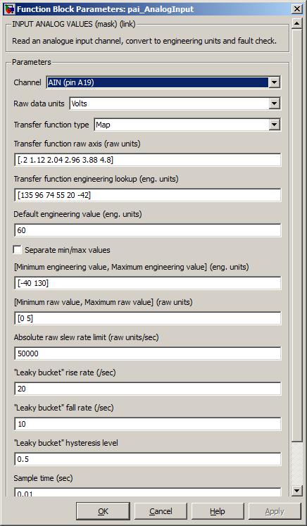
Set the block mask parameters as the figure shows. A full description of the block mask parameters is given later on Section 6.1.6, “Analogue input — processed (pai_AnalogInput)”, but a summary of the items and their meaning is given here for this example.
Table 3.4. Step1 - analogue input block parameters
| Parameter | Description | Set to |
|---|---|---|
| Channel | Which channel will be used for the raw input from the temperature sensor. |
AIN (pin A19) for M220,
AIN (pin A19) for M250, AIN (pin A28) for M460 and M461, or AIN (pin Y31) for M670 |
| Raw data units | Units in which the raw analogue values for this block are interpreted. | Volts |
| Transfer function type | The type of tranfer function to use when converting from raw values to engineering values. In this example we set it to use an interpolating lookup map. | Map |
| Transfer function raw axis | The values of this and the engineering lookup define a
transfer function that is characteristic of the particular
temperature sensor we're using. The raw axis defines some
arbitrary inputs to the sensor, and the eng lookup defines the
corresponding output behaviour. Note that the number here represents
the analogue pin voltage because Raw data units is
set to Volts. | [.2 1.12 2.04 2.96 3.88 4.8] |
| Transfer function engineering lookup | (see above) | [135 96 74 55 20 -42] |
| Default engineering value | The default starting value for the parameter (in °C). | 60 |
| Separate min/max values | Option to separate the Minimum/maximum engineering value and Minimum/maximum raw value into four separate parameters. Not used in this example. | unchecked |
| Minimum/maximum engineering value | The minimum and maximum values that are to be expected for this value (in °C). | [-40 130] |
| Minimum/maximum raw value | The minimum and maximum raw values that are expected at the input to
the block's transfer function. These units correspond to the setting of Raw data units,
hence the range for Volts. | [0 5] |
| Absolute raw slew rate limit | The maximum rate at which the signal is expected to rise or fall. By setting this to a large number, we can ensure that the block will never detect a slew rate limit fault. | 10000000 |
| Leaky bucket rise rate | This is the threshold rate above which incoming fault data will trigger a permanent fault. Setup for this example so that a fault is never detected. | 20 |
| Leaky bucket fall rate | This is the threshold rate below which incoming fault data will cease to trigger a fault indication. Setup for this example so that a fault is never detected. | 10 |
| Leaky bucket hysteresis | This is the amount of hysteresis in the leaky bucket fault filter system. Setup for this example so that a fault is never detected. | 0.5 |
| Sample time | The time (in seconds) between samples, i.e., how often this block will be integrated. | 0.01 |
The transfer function allows for non-linear conversion but must adhere to the same restrictions as the put_Calmap1d block (e.g., regarding axis monotonicity). The transfer function from the analogue input block data above in Figure 3.4, “Analogue input transfer function”.
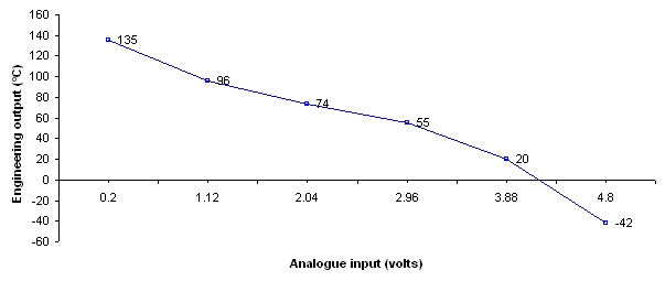
The parameters dialogue box for the PWM Output looks like this:
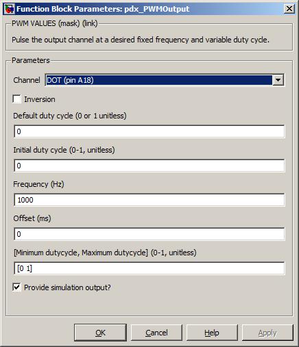
Set the block mask parameters as the figure shows. A full description of the block mask parameters is given later on Section 6.1.84, “PWM output — fixed frequency (pdx_PWMOutput)”, but a summary of the items and their meaning is given here for this example.
Table 3.5. Step1 - PWM output block parameters
| Parameter | Description | Set to |
|---|---|---|
| Channel | Which channel will be used for the PWM output signal. |
DOT (pin A37) for M220,
DOT (pin A18) for M250, DOT (pin A15) for M460 and M461, or DOT (pin Y29) for M670 |
| Inversion | Whether the logical function of the block will be inverted (ticked) or not (unticked). | (unticked) |
| Default duty cycle | The default output duty cycle used when a fault is specified. In this example, the fault inport is always force to zero, so this condition never arises. | 1 |
| Initial duty cycle | The initial duty cycle before the model starts to run. | |
| Frequency | The frequency of the signal. Although this example always uses a 0% or 100% duty cycle, i.e., always on or off, the frequency must still be specified. | 1000 |
| Offset | The offset of the signal relative to other PWM signals of the same frequency. An advanced feature that can be ignored in this case. | 0 |
| Minimum/maximum duty cycle | The minimum and maximum duty cycle range for this input. | [0 1] |
| Sample time | The time (in seconds) between block iterations. | 0.01 |
This example uses a PWM output to drive an output either fully on (100% duty-cycle) or fully off (0% duty-cycle). A digital output block Section 6.1.43, “Digital output (pdx_DigitalOutput)” could have been used instead and is the more logical choice for this example. However, the example uses a PWM output block to show that different outputs can be used in equivalent ways.
Your model should now look like Figure 3.5, “Configured quick start model”.
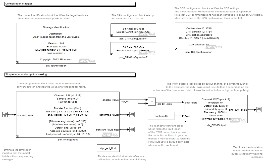
So far, you have populated the model with a number of Simulink and OpenECU blocks, defined some behaviour by linking the blocks together to interact and now need to provide the framework around the model to allow it to be built and run on an OpenECU device.
Your model file includes the information to describe the dynamics of your design, but it needs some other information — parameters and initial values of variables — to function correctly and remain flexible for future alterations and additions to its design. There are two types files that are used for this:
- Data dictionary
A text file which holds information about the variables you have set up in your design model that you will want to inspect on the physical system with the calibration tool. We created three variables in this model, whose initial conditions, ranges and types must be recorded in the data dictionary;
- M-file build list
A text file which tells the model where to find the blocks and data dictionaries that are to be used by the model. In this case, there is only 1 data dictionary used.
Draft versions of these resource files were created by the oe_create_model
command.
The data dictionary for this model will consist of 4 lines (1 for the column labels, and 3 others for the variables in our model). Each line needs to have 10 tab-delimited fields entered, which are used to tell the model about the type and structure of each of the 3 variables. As the data dictionary is a tab-delimited text file, it is often simpler to use a spreadsheet application (e.g. Microsoft Excel) to create or edit the file, although you can, of course, use any text editor. It is not recommended that you use MATLAB's own text editor for editing data dictionary files, as tab characters are handled poorly.
To edit the data dictionary for your model:
Use your spreadsheet application or text-editing application to open the file called
stp_dd.txtin the directory calledstpin the directory you created at the start of this exercise.The file has three lines — the top line always contains the column labels for reference, and the other two lines contain dummy variables to be replaced by variables from our model.
Copy and paste the line that starts with
stp_dummyso that the file looks like:Name Value Units Type Accuracy Min Max Description stp_dummy NA real_T 0.01 0 0 Dummy measurable, delete t ... stp_dummy NA real_T 0.01 0 0 Dummy measurable, delete t ... stpc_dummy_cal 0 NA real_T 0.01 0 0 Dummy calibratable, delete ...
Then change each line, making sure not to delete or add any TAB characters, so that the file looks like:
Name            Value  Units  Type    Accuracy  Min  Max  Description
stp_ect                degC   real_T  0.01      -40  140  Temperature of engine
stp_ect_state          state  BOOL    1         0    1    1 if over temperature, 0 if not
stpc_ect_limit  90     degC   real_T  0.01      -40  140  Temperature threshold
Save the file — if you're using a spreadsheet application to edit the data dictionary file, save in a tab-delimited text format.
At MATLAB's command prompt, issue the command:
oe_read_build_listwhich deletes the dummy workspace variables and replaces them with the set of variables entered into the
stp_dd.txtfile. If any errors or warnings are displayed, go back and edit the file until it matches the above (a complete list of error and warning messages are given in Appendix H, Data dictionary tool errors).Once read without errors, the workspace will have been updated and look something like:
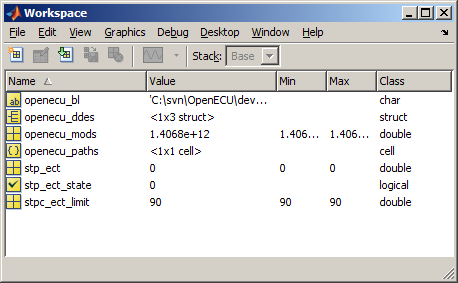
Optionally, in R2015a and later, a Simulink based data dictionary can be used in place of a text based data dictionary by issuing the following command, at MATLAB's command prompt:
oe_config_using_sim_ddThis will convert the text based data dictionary to a Simulink data dictionary which can then be edited within Simulink in Model Explorer.
More detailed information on the structure of the data dictionary can be found in Section 4.2.2.2, “Data dictionary files”.
The model is now complete, but before its built, we can check it by updating the model. This also activates a number of visual indicators which help the user read the model, including library links and rate colouring.
To update the model (right click on the background and select the Update diagram menu item). Your model should now look like Figure 3.6, “Updated quick start model”.
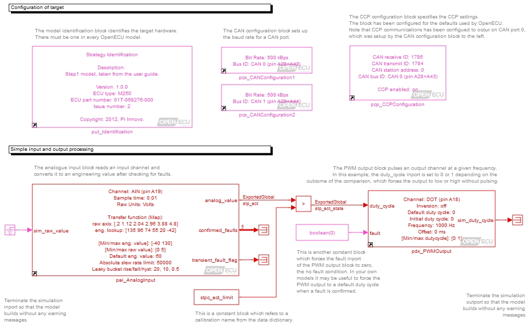
- Library links
Each of the OpenECU blocks has a small icon of an arrow in the bottom left hand corner of the block display. This indicates that the block on the screen is a reference to the OpenECU library.
It is possible to break the library links but its very important that OpenECU blocks remain as library links. When they remain as library links, when the OpenECU software is updated, linked blocks are updated as well. If the link were broken, then the OpenECU software is updated, the unlinked block remains at the older version of OpenECU.
Warning
Mixing versions of OpenECU blocks in a model may lead to undefined results when the model is simulated or run on the target.
- Block and signal colouring
All of the blocks and signals have been coloured red (or magenta). This means that all the blocks run at the same rate and that the rate is the fastest in the model. If other rates were present in the model, Simulink would colour blocks and signals that run at those rates different colours.
Table 3.6. Simulink model colouring
Colour Description Red Fastest discrete sample time Green Second fastest discrete sample time Blue Third fastest discrete sample time Light blue Fourth fastest discrete sample time Dark green Fifth fastest discrete sample time Orange Sixth fastest discrete sample time Black Continuous blocks — these cannot be used with OpenECU. Cyan Blocks in triggered sub-systems — triggered sub-systems do not have a defined periodic rate and run sporadically when the trigger activates. Yellow A mixed or hybrid system which contains more than one rate. Purple/Magenta An invariant or constant — something which does not change during the run of the model. Simulink will try to optimise these items. The colouring is a very useful indicator of related tasks and helps the model designer break up the functionality between rates. As much as possible, functionality should be placed at the slowest rate possible to ensure that as much computing power on the ECU is made available.
- Exported global indication
Signals that need to be viewed while the model is running on the target must be defined as Exported Global. When the model is updated, Simulink explicitly shows the Exported Global item on the diagram and its a useful indicator in case you forgot to set the type.
- Vectors of signals
The analogue input block shows a vector of outputs as a thick line with the number 5 written beside it. This means the vector contains 5 elements. More information about each of those elements can be found in Section 6.1.6, “Analogue input — processed (pai_AnalogInput)”.
To run your model in simulation prior to running it on OpenECU target hardware select Start from the Simulation menu, or click on the button in the Simulink toolbar. If your model has no design errors in it, and Simulink can find all the resources it needs, the simulation will run.
Of course, for this example, you cannot change the behaviour of the simulation as it runs. In order to do this, you can replace the ground input to the pai_AnalogInput block with a signal generator and attach scopes to the signals to view during the simulation.
The process of building the model creates a number of files which
can be downloaded or programmed into an OpenECU to run in real-time. The
build process is started by selecting the model, and either pressing
CTRL-B or selecting the menu option
Tools -> Real-Time Workshop -> Build Model.
This instructs RTW to generate C code from the model and to invoke
OpenECU's template makefile to compile the C code.
The result of a successful build produces a number of files in the same directory as the step1 model:
step1_tool_generic.a2l — the generic ASAP2 file for the build model (includes details about the
stpsignals amongst other things);step1_tool_inca.a2l — the ETAS INCA specific ASAP2 file for the build model;
step1_tool_vision.a2l — the ATI Vision specific ASAP2 file for the build model;
step1_tool_canape.a2l — the Vector CANape specific ASAP2 file for the build model;
step1_tool_vision.vst — the ATI Vision Strategy file for the build model (combined ASAP2 and S-record files — only generated if a compatible version of ATI Vision is installed);
step1.a2l.err — any errors that resulted from creating the ASAP2 file (if there are any errors, a short extract is displayed at the end of the build);
step1_image_small.s37 — the image bytes to program into the OpenECU in Motorola S-record format (small representing the minimum amount of code and data bytes to program the OpenECU device) — suitable for the ATI Vision calibration tool;
step1_image_small.hex — the image bytes to program into the OpenECU in Intel HEX format — suitable for the Vector CANape and ETAS INCA calibration tool;
step1.elf — the compiler's version of some of the above files — suitable for the PiSnoop development tool;
step1.snx — lists of variables PiSnoop will show or hide automatically — suitable for the PiSnoop development tool;
If the build fails for any reason, go back through the stages of the example and identify any corrections, or look at the installed and completed step1 model to identify any differences.
The OpenECU is programmed with any CCP compliant tool. Specific instructions for ATI Vision, Vector CANape and ETAS INCA calibration tools are provided in Appendix B, Supporting tools.
At a minimum, the OpenECU device will need to be powered and be connected to the CCP tool over CAN as shown in the following diagram.
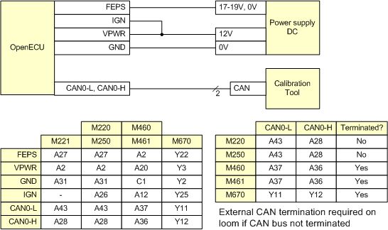
The OpenECU device can be programmed by following these steps:
Apply a positive FEPS voltage, as given in the following table and then power cycle the ECU (the FEPS signal may not be detected if applied simultaneously with the ECU power). Upon detecting the FEPS signal the ECU is placed into its reprogramming mode, where it does not run the application and responds only to reprogramming commands.
Program the ECU following the instructions in Appendix B, Supporting tools.
Once programmed, ground the FEPS pin and power cycle the ECU. This places the ECU in its application mode, where the ECU runs the programmed application.
Table 3.7. FEPS voltages
| M110 | M221 | M250 |
M220
M460 M461 M670 | Result |
|---|---|---|---|---|
| 0V | 0V | 0V | 0V | FEPS pin is grounded. On power up, the ECU attempts to run the last programmed application in application mode. If a application has not been programmed, the ECU enters reprogramming mode. |
| — | > +36V | > +13V | > +17V | FEPS pin is positive. On power up, the ECU enters reprogramming mode. If a application has previously been programmed, the ECU uses the CCP settings of the application. Otherwise, the ECU uses the default CCP settings. |
| < -16V | < -16V | < -18V | < -16V | FEPS pin is negative. On power up, the ECU enters reprogramming mode. The ECU uses the default CCP settings and ignores any CCP settings stored in any programmed application. |
- 4.1. How to find OpenECU
- 4.2. Introduction to OpenECU
- 4.3. Simulink and OpenECU
- 4.4. System modes
- 4.5. Programming an ECU
- 4.6. OpenECU blockset features
- 4.6.1. Calibration tool support
- 4.6.2. Adaptive parameters
- 4.6.3. Communications
- 4.6.4. Compiler options
- 4.6.5. Deprecated blocks
- 4.6.6. Fault support
- 4.6.7. PID support
- 4.6.8. Freeze Frame support
- 4.6.9. Service $09 InfoType support
- 4.6.10. IUPR support
- 4.6.11. Analogue and digital inputs
- 4.6.12. Oxygen sensing — wide band UEGO
- 4.6.13. Operating system
- 4.6.14. Analogue and digital outputs
- 4.6.15. Real-Time Workshop (RTW) support
- 4.6.16. Target ECU identification and configuration
- 4.6.17. Timing
- 4.6.18. Utilities
- 4.6.19. Versioning
- 4.7. Adapting an existing model for OpenECU
- 4.8. Migrating between versions of Simulink
This chapter provides an overview of OpenECU developer software in more depth than the quick start covered in Chapter 3, Quick start. From this chapter, you will:
Understand how to access OpenECU through Simulink, in particular, the OpenECU blockset and user guides.
Understand the process in creating and developing an OpenECU Simulink application, how OpenECU uses data dictionaries to describe the signals and constants in the model, and how to program an ECU with that application.
Understand how to interact with the different Simulink coders through configuration sets, as well as what features of Simulink are not supported by OpenECU.
Understand the different system modes an ECU select, including the different software components that make up the ECU's firmware.
During the installation of OpenECU, menu items are added to Windows Start menu. You can access OpenECU documentation by selecting the Start menu, then OpenECU Developer Software, then the version of OpenECU that is of interest:

Having asked for MATLAB integration during the installation of OpenECU developer software, the OpenECU blockset is available to use from within Simulink. The integration with MATLAB resembles other blocksets, and as closely as possible, OpenECU tries to integrate into the existing available MATLAB commands.
To find out if OpenECU was successfully installed, type the following command at the MATLAB prompt:
ver openecu
and MATLAB will display the version of OpenECU installed. A correct response will look something like:
          OpenECU Blockset (Pi Innovo)
          Version 2.9.0 (r2020-1)
Note
The ver command is a MATLAB standard command. OpenECU
integrates with a small number of these commands, see Table 4.1, “Standard MATLAB commands”.
In MATLAB R2013a through R2015b, the user guide can be reached by selecting Help > Documentation from the main toolbar, then by selecting Supplemental Software on the window that appears. Finally select OpenECU (Pi Innovo) Blockset which is listed in the contents of the Supplemental Software window.
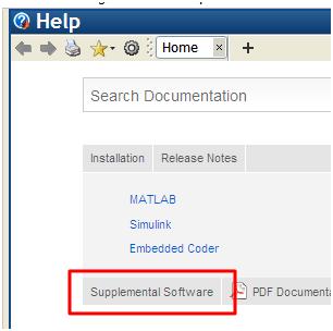
In MATLAB R2016a and later, the user guide can be reached by selecting Help > Documentation from the main toolbar, then by selecting OpenECU (Pi Innovo) Blockset.

The blockset is accessible through the library browser, which is itself available through any main Simulink window:
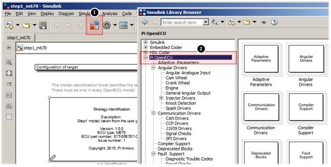
The functionality of OpenECU is split into various components (e.g., angular, input, output) and documented in Section 4.6, “OpenECU blockset features”. The blocks can be dragged from the library browser to a model.
The OpenECU blockset is integrated into MATLAB through various standard commands:
Table 4.1. Standard MATLAB commands
| Command | Description |
|---|---|
| ver | Display the versions of all toolboxes and blocksets MATLAB knows about. |
| ver openecu | Display the version of the OpenECU blockset only. |
| help openecu | Display the commands specific to OpenECU. Further help on each command
can be displayed by executing help <command> (e.g.,
help oe_freeccp). |
Note
If too much information is displayed at once when using these commands, the display can be broken into pages by executing the command:
more onthen repeating the command which displayed too much information.
Further commands specific to OpenECU are available and reference documentation is available in Section 6.4, “OpenECU commands”.
To help explain the methods for working with OpenECU, Figure 4.5, “Example development pattern for modelling an application” shows a simple development process for working with a model and an ECU.
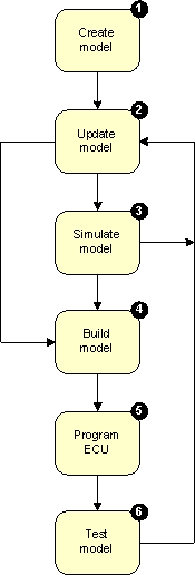
Create model — using the
oe_create_modelscript will create a basic model containing essential OpenECU blocks and will create a data dictionary. How to use this script and what a data dictionary is, is described in more detail in Section 4.2.2, “Create model”.Update model — by adding to the model's logic and algorithms, or amend what is already there with feedback from simulating or testing the model. Some tips on model structure can be found in Section 4.2.3, “Update model”.
Simulate model — on the PC using Simulink's simulation feature to quickly check the overall functionality of the model without having to power up an ECU. Sometimes its necessary or simply quicker to skip the simulation stage and try the model out on an ECU. While simulation can help spot problems before running the model on an ECU, it is essential to test the model on the ECU to confirm correct behaviour. Simulation is covered in Section 4.2.4, “Simulate model”.
Build model — to create the files necessary to program an ECU with the model. Building the model is taken care of by a combination of Simulink and OpenECU — there are no manual steps to creating the ECU files, except to start a model build. An overview of how to start a model build is given in Section 4.2.5, “Build model” and the automatic build process and outputs are detailed in a later section, Section 4.3.6, “Building a model”.
Program ECU — to place the built model onto an ECU ready to run. Typically, programming an ECU involves the use of a calibration tool and OpenECU is compatible with ATI Vision, Vector CANape and ETAS INCA. Programming an ECU is covered in detail in Section 4.5, “Programming an ECU”.
Test model — to determine if the model logic and algorithms perform adequately and provide any feedback to update the model. Some tips on testing can be found in Section 4.2.7, “Test model”.
An OpenECU model consists of three or four components:
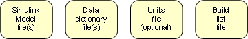
- Simulink model file(s)
One or more Simulink model file which use Simulink and OpenECU (and possibly custom) blocks to detail the functionality of the application. The model files are covered in Section 4.2.2.1, “Model”.
- Data dictionary file(s)
One or more text files or Simulink data dictionary files which detail each of the named block parameters and named signals in the Simulink model. Details include units, range, description, and more. The data dictionary files are covered in Section 4.2.2.2, “Data dictionary files”.
- Units file
An optional text file which lists the allowable units used to describe named parameters and signals in the model. The units file is covered in Section 4.2.2.3, “Units file”.
- Build list file
One MATLAB file which lists the data dictionary files used by the model. The build list file is read when the Simulink model is loaded into Simulink and the workspace is populated with data dictionary information. The build list file is covered in Section 4.2.2.4, “Build list file”.
Note
Simulink Data Dictionaries are supported in R2015a and later.
An OpenECU model can be created by:
creating a new directory to store the model;
changing MATLAB's current path to the newly created directory;
issuing the following command at MATLAB's prompt:
oe_create_model '[model-name]' 'dd' '[dd-name]' 'part' '[part-number]' 'template' 'basic'Where the text
[model-name]is replaced by the name to be given to the model, the text[dd-name]is replaced by the name of the data dictionary and the text[part-number]is replaced by the part number of the target (e.g.,01T-068144-000for the M460-000). The command opens a new Simulink model, creates a basic build list and data dictionary file, adds put_Identification block to configure the ECU.The model parameters are important to the correct working of OpenECU models and are discussed in a little more detail in the following sections.
save the model.
The procedure above uses a default name for the data dictionary and a default version of hardware but these can be specified when creating the model.
oe_create_model('model-name', 'dd', '[dd_name]', 'part', '[part-number]')where [dd_name] is replaced by the name of the data dictionary (e.g., the step1 model from Section 3.3, “Exercise — Step 1” uses a data dictionary named stp) and where [part-number] is replaced by the part-number of the target (see Section 6.1.63, “Model identification (put_Identification)”). For more details, issue this command at MATLAB's command window:
help oe_create_model
The oe_create_model command will not be able
to create a new model when it cannot understand some of the parameters
given to it or if it cannot access the file system (e.g., if
the file cannot be written or the file system is full).
If an error does occur when creating the model, once the problem
that caused the error has been resolved, it is best to remove the
intermediate set of files that the oe_create_model
command generated, before issuing the command a second time.
A data dictionary can be either a text file, or a Simulink proprietary format file with the extension .sldd starting in R2015a. Prior to R2015a only text file based data dictionary files are supported.
A text file based data dictionary file is a simple tab delimited text file format and must contain at minimum: the name, default value and type for calibratables and the name and type only for displayables. When a model is loaded, the data dictionary files are read into MATLAB's workspace to support simulation or building. Optionally, these can be used to generate ASAP2 files at build time. See Section 4.3.4, “Configuration options” for details.
Note that non-ASCII characters appearing in the data dictionary may not be interpreted correctly by the calibration tool reading the resultant ASAP2 files, since different calibration tools use different extended encoding conventions. It is best therefore to stick to ASCII characters within the data dictionary.
Each data dictionary file is stored in a directory of the same name.
Given the example of the model read_sensor above, then
there would be two directories named min and
mot:

Each data dictionary file stored in each of those directories must be
named data dictionary name_dd.txt.
Given the example of the model read_sensor above, then
there would be two files named min_dd.txt and
mot_dd.txt in the corresponding directories:
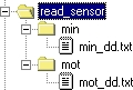
Each data dictionary follows a simple format, separated into columns and will look something like:
Name            Value  Units  Type    Accuracy  Min  Max  Description
moi_pressure           kPa    real_T  0.01      20   80   Pressure reading
moi_temperature        degC   real_T  0.01      -40  150  Temperature reading
To help readability, comment lines can be inserted into a data dictionary file.
Comment lines are ignored and start with either a **
or the -- character sequence. For example:
Name            Value  Units  Type    Accuracy  Min  Max  Description
** A comment line
moi_pressure           kPa    real_T  0.01      20   80   Pressure reading

-- Another comment line
moi_temperature        degC   real_T  0.01      -40  150  Temperature reading
Each column has a heading, followed by as many data dictionary entries
as necessary. Each column is separated by a TAB character
and because of this, Excel is a very useful tool for editing the
files (in Excel, save the file as Text (tab delimited) *.txt).
Each column has a use:
Table 4.2. Data dictionary columns
| Column | Description |
|---|---|
| Name | The name of the data dictionary entry. The name must conform to the naming convention detailed in Section 5.2.5, “Naming rules”. |
| Value | The value of a calibration constant, 1d or 2d map. A value should not be created for a Simulink signal. |
| Units | The engineering units for this entry (can be restricted to a set of possibilities with a units file (Section 4.2.2.3, “Units file”)). |
| Description | A description of the data dictionary entry. Must not contain single or double quotes. |
| Type | Any one of int8_T, uint8_T,
int16_T, uint16_T, int32_T
uint32_T, real_T or bool.
The type must match the type assigned to the signal by Simulink. |
| Accuracy | The number of decimal digits to display when viewing the
data dictionary entry with a calibration tool. For instance,
1 shows no digits after the decimal point,
0.01 shows two digits after the decimal point. |
| Min | The minimum expected value for this data dictionary entry. |
| Max | The maximum expected value for this data dictionary entry. |
| Scale | This column is optional. It specifies the amount by which the displayed value will be scaled from the raw value read from the ECU. |
| Offset | This column is optional. It specifies the amount by which the displayed value will be offset from the raw value read from the ECU. |
| Enums | A comma separated list of data dictionary entries which provide the possible values this data dictionary entry can be. This column is optional. |
| Defn | This column is optional. It specifies the file in which the equivalent C variable for the DDE will be defined. Only applicable when using RTW Embedded Coder, the column is ignored for other auto-coders. |
| Decl | This column is optional. It specifies the file in which the equivalent C variable for the DDE will be declared. Only applicable when using RTW Embedded Coder, the column is ignored for other auto-coders. |
| Lookup | Reserved for future use, do not use. |
| Group | Reserved for future use, do not use. |
| Rate | Reserved for future use, do not use. |
An example of how the data dictionary can be used to name model signals, model constants and map look-ups is given below. Each entry follows the naming convention laid out in (Section 5.2.5, “Naming rules”). Explore the OpenECU demos for more examples (Section 3.2, “Installed examples”).
Name           Value               Units  Type    Min Max  Description

** Example of a signal DDE
moi_pressure                       kPa    real_T  20  80   Example of a named signal

** Example of a constant look-up DDE
moic_constant  50                  kPa    real_T  20  80   Example of a calibration constant

** Example of set of a 1D table/map look-up DDEs
moim_1d_map_x  [20 40 80]          kPa    real_T  20  80   Example of a x-axis for a 1d map
moim_1d_map_z  [0  0  1]           state  bool    0   1    Example of a z-data for a 1d map

** Example of set of a 2D table/map look-up DDEs
moim_2d_map_x  [20 40]             kPa    real_T  20  80   Example of a x-axis for a 2d map
moim_2d_map_y  [1  5  10]          sec    real_T  0   25   Example of a y-axis for a 2d map
moim_2d_map_z  [0  1; 4  5; 8  9]  steps  real_T  0   100  Example of a z-data for a 2d map

** Example of set of an array DDE
moiv           [1 2 3 5 8 13]      counts real_T  0   100  Example of an array
Instead of using values to represent discrete states, enumerations
can be used instead. These represent the discrete states using
a textual name rather than a number. For instance, in the following
example, moi_state can have two enumerations:
MOI_RUNNING which represents the value 0 and
MOI_STOPPED which represents the value 1.
It is easier to understand and interpret the enumerations than the
values.
Name         Value  Units  Type    Min  Max  Enums                     Description

moi_state           state  real_T  0    1    MOI_RUNNING, MOI_STOPPED  Example of a st ...

MOI_RUNNING  0      enum   real_T                                      Enumeration for ...
MOI_STOPPED  1      enum   real_T                                      Enumeration for ...
When a model is loaded, each data dictionary entry is checked for errors. A complete list of checks is given in Appendix H, Data dictionary tool errors. If any errors or warnings are displayed, go back and edit the file to remove the errors.
Note
When a data dictionary is changed OpenECU does not automatically read the file. Instead, the user must read the data dictionaries by running the command:
oe_read_build_list
at MATLAB's prompt.
In R2015a and later, a Simulink based data dictionary file with an extension of .sldd
can be used with OpenECU. This type of data dictionary holds the same information
as a text based data dictionary, only the data is stored in oe.Parameter
and oe.Signal objects in the data dictionary file from within Simulink,
instead of externally in text files. This file can be edited manually from within
Simulink using the Model Explorer interface, or programmatically in Simulink using the
Simulink.data.dictionary class and API.
The data dictionary file is specified in the Model Properties dialog box of the model File-> Model Properties-> Model Properties under the Data tab, as shown in the image below.
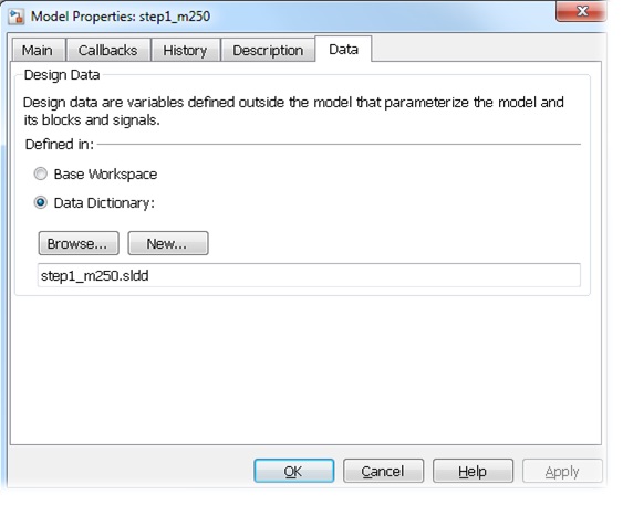
The data dictionary file can be viewed or edited by clicking the icon in the bottom left hand corner of the model once it has been configured to use a data dictionary, as shown below.
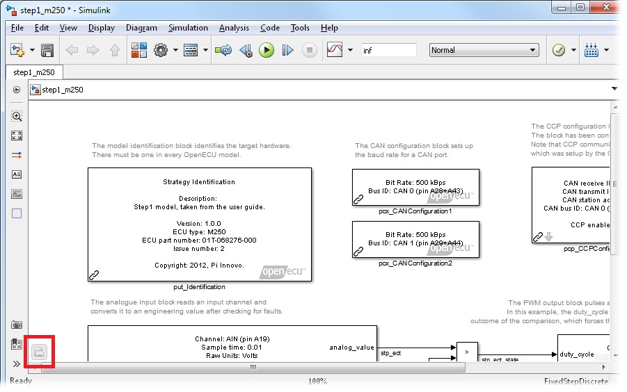
The data dictionary file is then edited in Model Explorer Tools-> Model Explorer, as shown below.
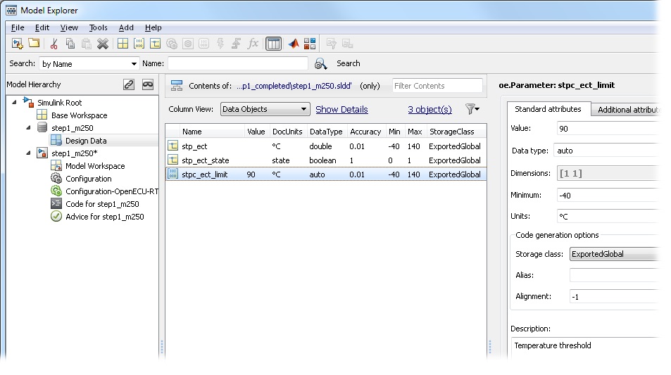
To add a new oe.Parameter or oe.Signal object to the data dictionary
select Add-> Add Custom... from the Model Explorer menu, and in the dialog box, specify
the name of the variable and the class of the variable (either oe.Parameter or
oe.Signal), as shown below.
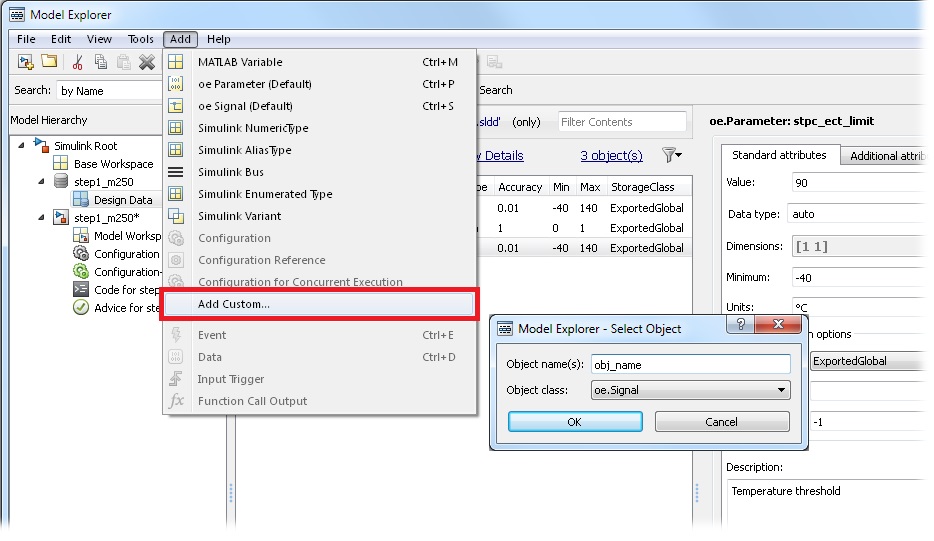
OpenECU uses the following properties for each signal object:
Table 4.3. Simulink data dictionary object properties
oe.Parameter property | oe.Signal property | Text based column equivalent | Description |
|---|---|---|---|
| Object name | Object name | Name | The name of the object in the data dictionary. The name does not need to conform to the naming convention if the model is configured to use oe objects, and to disable the naming convention. |
| name.Value | Value | The value of a paramter constant, 1d or 2d map.
Only valid for oe.Parameter objects. | |
| name.DocUnits | name.DocUnits | Units | The engineering units for this entry. Units file is not supported. |
| name.Description | name.Description | Description | A description of the data dictionary entry. |
| name.DataType | name.DataType | Type | A Simulink supported data type. |
| name.Accuracy | name.Accuracy | Accuracy | The number of decimal digits to display when viewing the
data dictionary entry with a calibration tool. For instance,
1 shows no digits after the decimal point,
0.01 shows two digits after the decimal point. |
| name.Scale | name.Scale | Scale | The amount by which the displayed value will be scaled from the raw value read from the ECU. |
| name.Offset | name.Offset | Offset | The amount by which the displayed value will be offset from the raw value read from the ECU. |
| name.Min | name.Min | Min | The minimum expected value for this data dictionary entry. |
| name.Max | name.Max | Max | The maximum expected value for this data dictionary entry. |
| name.Enums | name.Enums | Enums | A comma separated list of oe.Parameter objects which provide the possible values this data dictionary entry can be. This property can be left blank. |
|
name
|
name
| Defn | This property is optional. It specifies the file in which the equivalent C variable for the DDE will be defined. Only applicable when using Embedded Coder, the property is ignored for other auto-coders. |
|
name
|
name
| Decl | This property is optional. It specifies the file in which the equivalent C variable for the DDE will be declared. Only applicable when using Embedded Coder, the property is ignored for other auto-coders. |
With a Simulink data dictionary, in order to make each variable available in a calibration tool, the variable must have certain properties set in order to control the storage of that variable. The properties must be set differently depending on the auto-coder used (see Section 4.3.2, “Auto-coders” for more details about auto-coders), and the desired type and scope of the variable.
The following table details the desired variable type in the model or calibration tool, and the data object and properties required for each auto-coder which must be set to generate that variable in the model and make available in the calibration tool:
Table 4.4. Simulink data dictionary object storage classes
| Variable type | Auto coder | Data object | Properties |
|---|---|---|---|
| Constant scalars | any | oe.Parameter |
name
|
|
Calibration scalars Calibration maps (1d or 2d), or Arrays | GRT RTMODEL | oe.Parameter |
name
|
| Displayable signals | GRT RTMODEL | oe.Signal |
name
|
|
Calibration scalars Calibration maps (1d or 2d), or Arrays | EC | oe.Parameter |
name
name
name
|
| Displayable signals | EC | oe.Signal |
name
name
name
|
Note
In the Model Explorer interface, the name.CoderInfo.StorageClass, and name.CoderInfo.CustomStorageClass, properties are normally merged into the same drop down selection field. The 'Global (Custom)' selection will select both name.CoderInfo.StorageClass = 'Custom' and name.CoderInfo.CustomStorageClass = 'Global' at the same time.
Note
The oe.Signal and oe.Parameter object classes are
derived from the native Simulink.Signal and Simulink.Parameter
classes and are designed to better integrate with OpenECU projects. It is highly recommended
to use the OpenECU specific object whenever possible, as the Simulink native object classes
are not officially supported by OpenECU.
A model configured to use a text based data dictionary can be automatically converted to use a Simulink data dictionary with all of the existing data dictionary entries imported into the .sldd file by calling the following command:
oe_config_using_sim_dd
at MATLAB's command prompt.
By default, the script will convert the currently active model, using the data dictionary file name
model-name.sldd. If the data dictionary file already exists
it can be overwritten with additional parameters. See details at oe_config_using_sim_dd.
In addition to the previously mentioned data dictionary variables, additional data can also be stored in a Simulink data dictionary file, such as Simulink.Bus objects, Simulink enum type definitions, Configuration Sets, and other built-in Simulink types. Please refer to the Simulink documentation for further details on the data that can be stored in a Simulink data dictionary file.
A units file is a simple text file format, where each line represents a single allowable unit. When a model is loaded, the data dictionary entries and unit entries are read, and any data dictionary that does not use one of the unit entries raises a warning.
A units file is only supported with text based data dictionaries.
A units file is stored in the same directory as the model.
A units file for a model must have the file-name
model-name_units.txt where
model-name is replaced by the name of the model. An
example units file for a model named read_sensor
would be named read_sensor_units.txt and might look like:
degC
kPa
In this example, only two units: degC or kPa, can be used for each data dictionary entry.
To help readability, comment lines can be inserted into the units file.
Comment lines are ignored and start with either a **
or the -- character sequence. For example:
** Allowable units for the read_sensor model
degC
kPa
A build list file is a simple m-script that specifies what the data dictionary files are called. When a model is loaded, the build list is read to determine which data dictionaries are to be read into MATLAB's workspace.
A build list file for a model must have the file-name
model-name_bl.m where
model-name is replaced by the name of the model. An
example build list file for a model named read_sensor
would be named read_sensor_bl.m and would like very
similar to:
feature_list = [{'min',
                 'mot'}];
In this example, the build list defines two data dictionary files, named
min and mot. Further data dictionary
files can be added by extending the vector feature_list.
It is important to use three characters for each data dictionary name.
If a model is configured to use a Simulink data dictionary, the build list file will only list the feature directories which are to be added to the MATLAB path. The data dictionary files are specified within the model properties.
The update model stage adds or adjusts the functionality of the model. It's important to keep the data dictionary files up to date with changes to the model. It's easy to leave changes to the data dictionary until later, but that often leads to multiple build and update cycles as missing data dictionary elements are found during the testing stage.
Before Simulink starts to simulate a model on the host PC, or builds a model
to run on an ECU, Simulink attempts to solve the model and applies consistency
checks during the solving. This process is called a diagram update.
A diagram update can be performed at any point by pressing CTRL+D
in a model window, or by selecting the Edit -> Update diagram.
Note
It is useful to periodically update the model diagram to check that everything has been accounted for. However, Simulink does not provide a mechanism for OpenECU to ensure the text based data dictionary files have been incorporated into the model. Therefore, if the data dictionary files have been updated, prior to a diagram update, the user must issue the following command:
oe_read_build_list
at MATLAB's command prompt to ask OpenECU to read the data dictionary files.
If you are unfamiliar with Simulink models then note that it is worth the extra effort up front to partition your application into smaller blocks of functionality. Each block of functionality is placed in a subsystem. With complex areas of functionality, breaking those areas of functionality into less complex interrelated blocks, each within a subsystem, can help readability.
Simulink provides a Model Explorer tool which makes it easy to navigate between parts of the model based on the hierarchy of the subsystems. And OpenECU can incorporate the model hierarchy into the files used to communicate with the ECU while the ECU is running the model.
For instance, at a top level, a useful pattern to follow breaks the model into an input, output and application subsystem.
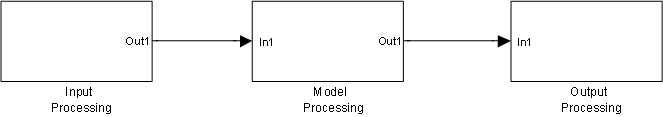
- Input processing
The input subsystem reads sensor and actuator feedback signals and decodes communication messages, transforming raw sensor information into engineering units (possibly applying filters and other validation techniques to ensure the input data is usable). The input subsystem can be broken down into further subsystems, perhaps one to read the raw sensor information, one to process into engineering units, and one to validate the inputs (perhaps against other sensor inputs or against a plant model of the system under control).
- Application processing
The model subsystem processes the input subsystem data, determining how the system it is controlling should react. The model subsystem would be further broken down into smaller subsystems, each performing a small portion of the overall functionality. The model subsystem creates the data in engineering units necessary to drive the output subsystem.
- Output processing
The output subsystem drives the actuators connected to the ECU to achieve the demands of the model subsystem.
By breaking the model into these subsystems, the input and output subsystems can easily be replaced when targeting another ECU. For instance, when moving to a more powerful ECU because the application has grown, or when moving to a less powerful ECU because the production needs for the prototyped application mean a cheaper ECU can be used.
Simulink provides a mechanism to simulate the model on the host PC. Please refer to the Simulink documentation for further details. Note that while simulation has many uses, it is not necessary to simulate the model before building the model to run on an ECU.
With the application model and data dictionary files in place, the application model can be built and linked with the OpenECU and compiler libraries to generate a binary image which can be programmed and run on an OpenECU.
To start a build, press CTRL+B in a model window, or select
the menu option Tools -> Real-Time Workshop -> Build model.
Detail on the build process, the generated build files and a summary of common issues can be found in Section 4.3.6, “Building a model”.
The OpenECU is programmed with any CCP compliant tool. Specific instructions for ATI Vision, Vector CANape and ETAS INCA calibration tools are provided in Appendix B, Supporting tools.
At a minimum, the OpenECU device will need to be powered and be connected to the CCP tool over CAN as shown in the following diagram.
The OpenECU device can be programmed by following these steps:
Apply a positive FEPS voltage, as given in the following table and then power cycle the ECU (the FEPS signal may not be detected if applied simultaneously with the ECU power). Upon detecting the FEPS signal the ECU is placed into its reprogramming mode, where it does not run the application and responds only to reprogramming commands.
Program the ECU following the instructions in Appendix B, Supporting tools.
Once programmed, ground the FEPS pin and power cycle the ECU. This places the ECU in its application mode, where the ECU runs the programmed application.
Table 4.5. FEPS voltages
| M110 | M221 | M250 |
M220
M460 M461 M670 | Result |
|---|---|---|---|---|
| 0V | 0V | 0V | 0V | FEPS pin is grounded. On power up, the ECU attempts to run the last programmed application in application mode. If a application has not been programmed, the ECU enters reprogramming mode. |
| — | > +36V | > +13V | > +17V | FEPS pin is positive. On power up, the ECU enters reprogramming mode. If a application has previously been programmed, the ECU uses the CCP settings of the application. Otherwise, the ECU uses the default CCP settings. |
| < -16V | < -16V | < -18V | < -16V | FEPS pin is negative. On power up, the ECU enters reprogramming mode. The ECU uses the default CCP settings and ignores any CCP settings stored in any programmed application. |
Once the ECU has been programmed, the ECU remains in reprogramming mode until the ECU is restarted by power cycling the ECU. Without FEPS applied, the ECU will enter application mode and run the model.
The testing phase seeks to ensure that the built Simulink model acts as expected under all circumstances. OpenECU provides a CCP interface to allow calibration tools to access model information. See Appendix B, Supporting tools for an introduction to how to use one of the supported calibration tools to monitor the model while it runs on the ECU.
The OpenECU blockset provides varied access to the features of both Simulink and the target ECU. The OpenECU blockset includes a real-time operating system, methods to measure input quantities from ECU pins and internal ECU signals, methods to receive and transmit CAN messages, and a host of other functions. See Section 4.6, “OpenECU blockset features” for details.
The OpenECU blockset works with most Simulink and RTW features. However, there are a small number of restrictions. For instance, the OpenECU blockset is a discrete blockset and does not work with continuous time blocks. See Section 4.3.1, “Block use restrictions” for details.
The OpenECU blockset provides a number of additional RTW options. These options include setting the application stack size, controlling what binary files are created at the end of a build, through to selecting which compiler to use. See Section 4.3.4, “Configuration options” for details.
The OpenECU blockset works with RTW's auto-coders: Generic Real-Time (GRT) and Embedded Coder (EC). The blockset provides mechanisms to create configuration sets (which are sets of parameters which tell RTW how to generate code) for each of the auto-coders, and some utility blocks to quickly switch between configuration sets. See Section 4.3.2, “Auto-coders” for details.
While OpenECU works with most of the functionality of Simulink and RTW, there are only a few major restrictions when using the OpenECU blockset in conjunction with RTW. Those that must be avoided are discussed in more detail below.
- Cannot use continuous blocks
For some targets the auto-code generator cannot produce code for these blocks, and for those for which it can there is significant computational overhead. See the Simulink documentation for a list of continuous time blocks (including Derivative, Integrator, Memory, State-Space, Transfer Fcn, Transport Delay, Variable Transport Delay, Zero-Pole).
- Cannot divide by zero
Division by zero, or overflow due to division by very small numbers, will cause the model running on the OpenECU target hardware to create a large number (approximately 3.4E38) which will propagate into any calculation which uses it (M110, M220, M221, M250, M460, M461, and M670 targets). Restrict division by clamping the divisor to a finite, non-zero number.
- Cannot use algebraic loops
These occur when the output of a calculation appears as one of its inputs. In many applications a variable is updated based on a previous value. In such cases a loop can be avoided by inserting a unit delay (1/z) block. RTW cannot produce code if algebraic loops exist.
For readability purposes, it is best to show a unit delay block used to avoid an algebraic loop flowing from right to left. Where a unit delay block is used for other purposes (such as comparing successive values of a flow) it should be shown flowing left to right.
- Cannot use blocks that access elapsed timers
The concept of elapsed timers is not supported. These are where instead of blocks using an absolute time reference to determine the time between successive iterations, the time between successive iterations are determined relative to each other. This is a restriction imposed by the OpenECU product, not RTW.
- Cannot use dynamic memory
Blocks that require the use of C
malloc()or C++new(), or other dynamic memory are not supported. This is a restriction imposed by the OpenECU product, not RTW.- Cannot use C++
Blocks that require the use of C++ are not supported. This is a restriction imposed by the OpenECU product, not RTW.
- Cannot use non-inlined S-functions
User written non-inlined S-functions or other blocks that are non-inlined are not supported. This is a restriction imposed by the OpenECU product, not RTW.
Note that inlined S-functions are supported, see Section C.2, “Custom C code” for more.
- Shared utility source and model references
Shared utility source and model references are only supported in Embedded Coder. Model references only support the put_Identification block. No other OpenECU block is supported in model references, only native Simulink blocks. This is a restriction imposed by the OpenECU product, not RTW.
- Cannot iterate quicker than 1 millisecond
OpenECU schedules model rate tasks at a resolution of 1 millisecond. This is a restriction imposed by the OpenECU product, not RTW.
Simulink Coder (formerly Real-Time Workshop) provides a number of different auto-coders, each with increasing levels of functionality:
- Generic Real-Time — RTMODEL
The GRT RTMODEL auto-coder is available with a license of Simulink Coder (or Real-Time Workshop) and provides the next level of auto-coding.
Although similar to GRT RSIM, the overall structure of the generated code is more like Embedded Coder. This auto-coder provides better memory use (making more memory available to the model) and generates better code in some situations.
This auto-coder is appropriate for rapid-prototyping tasks only.
- Embedded Coder
The EC auto-coder is available with a license of Embedded Coder (or Real-Time Workshop Embedded Coder). This license is separate from the Simulink Coder license.
This auto-coder provides good control over the generation of functions, of variable and function naming, of memory allocation and code layout within files. This auto-coder improves on memory use and again generates better code in various situations.
These improvements make this auto-coder suitable for production tasks.
See OpenECU Compatibility with Third Party Tools for a complete list of supported coder versions.
OpenECU provides a collection of configuration sets to select between each of these auto-coders.
A configuration set comprises groups of related parameters called components. These components provide various options which control how an auto-coder generates code from a model. Configuration sets can be viewed through Simulink's Model Explorer.
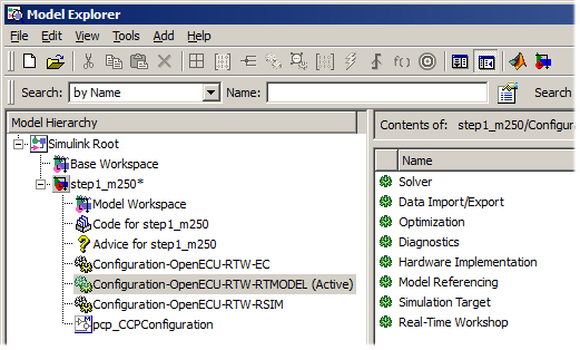
The picture in Figure 4.7, “Simulink's Model Explorer showing OpenECU configuration sets” shows an OpenECU configuration set for each of the auto-coders described in Section 4.3.2, “Auto-coders”. Only one configuration set is used at any time and Simulink shows this by marking it active (in this case, the GRT RTMODEL auto-coder is active).
Each of the components is listed in the middle pane. Selecting any of the components shows the component options in the right hand pane. Although it is possible to modify these options, it is recommended that models keep the original OpenECU settings.
OpenECU provides a number of configuration options which affect the build process. The
options can be accessed by opening an OpenECU model and selecting the menu option
Simulation-> Configuration Parameters... (or
Simulation-> Model Configuration Parameters in later versions of Simulink)
then browsing to the OpenECU options under Real-Time Workshop
(or Code Generation in later versions of Simulink).
Under the Real-Time Workshop (or Code Generation in later
versions of Simulink) categories, there are both built-in Simulink options, and OpenECU
additional options.
The built-in Simulink options that OpenECU recognizes are:
Interface
- Interface
The OpenECU build process will recognize the "ASAP2" setting for this parameter. This option will set the parameter 'GenerateASAP2' to 'on', and during the build process, an ASAP2 file will be generated using Simulink's built-in ASAP2 generation process in place of the OpenECU ASAP2 generation process.
The OpenECU additional options are grouped into the following categories:
OpenECU code generation options
This group of options affects the model generated code before it is built.
- Angular rate functionality (deprecated)
Ensure this option is selected if the model has a pan_EngineConfig block configured to iterate part of the model synchronous to the engine crank input (i.e., not using a TDC-firing function-call trigger).
This option is deprecated and should not be used in preference to the TDC-firing function-call trigger outport from the pan_EngineConfig block. This option is retained for backwards compatibility and will be removed in a future version of the blockset.
- Maximum data dictionary entry name length
Specify the maximum data dictionary entry name length,the range should be between 31 and 255 characters. If a data dictionary identifiers exceeds the maximum length then a warning will be generated and the name will be shortened during the ASAP2 generation. If length is given a value of 0, then there will be no limit on identifier length.
- Re-read build list before building
When this option is selected and a build starts, OpenECU reads the build list and data dictionaries. This brings the latest information from the data dictionaries into the workspace and overwrites any changes to existing entries in the workspace.
- System stack size
Specifies the amount of RAM dedicated to stack usage. Stack is used by the auto-generated code and platform to maintain a working store of calculations. The default size of the stack is 5KB which should be large enough for most models. The size can be changed by altering the default, for instance, by reducing the value based on the automatic ASAP2 variable
mpl_max_used_stackto provide more RAM for model functionality.
OpenECU image generation options
This group of options affects what images are generated at the end of a build. An image is downloaded or flashed onto the ECU to run on target.
- Generate image as a S-record file
If selected, the OpenECU build process will generate a Motorola S-record file which represents the image to download. If not selected, the file is not produced (or deleted if it previously existed).
If the S-record file is produced, it is named
model_name_image_small.s37wheremodel_nameis replaced by the name of the model.- Generate image as a Intel HEX file
If selected, the OpenECU build process will generate an Intel HEX files which represent the image to download. If not selected, the file is not produced (or deleted if it previously existed).
If the HEX file is produced, it is named
model_name_image_small.hexwheremodel_nameis replaced by the name of the model.- Generate ATI Vision strategy file
If selected, the OpenECU build process will attempt to generate an ATI Vision strategy file. The build process does this by invoking the ATI Vision tool, so the tool must be installed on the machine which builds the model. This feature is supported if the ATI Vision software is version 2.0 or above.
If not selected, the Vision strategy file is not produced (or is deleted if it previously existed).
If a strategy file is produced, it is named
model_name.vstwheremodel_nameis replaced by the name of the model.- Continue building if creation of ATI Vision strategy file fails
If selected, the OpenECU build process will ignore any failures to generate an ATI Vision strategy file. This can occur, if the wrong version of ATI Vision is used to generate the strategy file.
If not selected, the OpenECU build process will stop when there is a failure to generate an ATI Vision strategy file.
OpenECU ASAP2 generation options
This group of options affects the ASAP2 generated file (and the ATI Vision Strategy file if selected).
- ASAP2 naming scheme
This option provides a number of naming schemes that can transform the DD entry names in any generated ASAP2 file.
Data dictionary names take the form
prefix_name(as detailed in Section 5.2.5, “Naming rules”) and are used for each ASAP2 entry. Some calibration tools can group names together based on the prefix (for instance, ATI Vision's Structure naming: Names as groups import feature). This feature converts the data dictionary names before inserting them into the ASAP2 file to match tool features.Table 4.6. ASAP2 naming schemes
Scheme Description prefix_name Keep data dictionary names unchanged, e.g., mbe_engine_rpmremains asmbe_engine_rpmprefix.name Change mbe_engine_rpmtombe.engine_rpmprefix.name_prefix Change mbe_engine_rpmtombe.engine_rpm_mbename Change mbe_engine_rpmtoengine_rpmname_prefix Change mbe_engine_rpmtoengine_rpm_mbe- Generate automatic platform ASAP2 entries
If selected, the OpenECU build will generate a set of ASAP2 entries with the prefix
mpl. These entries provide information about the build time and run time as detailed in Section 6.2, “Automatic ASAP2 entries”.If not selected, these automatic variables are not generated.
- Generate generic ASAP2 file
If selected, the OpenECU build process will generate a generic ASAP2 file that should be readable by any calibration tool. The ASAP2 file contains only information about DD entries. The user will need to tell the tool about memory regions and CCP settings.
If not selected, the generic file is not produced (or deleted if it previously existed).
If a generic ASAP2 file is produced, it is named
model_name_tool_generic.a2lwheremodel_nameis replaced by the name of the model.- Generate ATI Vision ASAP2 file
If selected, the OpenECU build process will generate an ASAP2 file tailored specifically for the ATI Vision calibration tool. If not selected, the Vision file is not produced (or deleted if it previously existed).
If a ATI Vision ASAP2 file is produced, it is named
model_name_tool_vision.a2lwheremodel_nameis replaced by the name of the model.Note
If the Generate ATI Vision Strategy file option is selected, this option need not be selected.
- Generate ETAS INCA ASAP2 file
If selected, the OpenECU build process will generate an ASAP2 file tailored specifically for the ETAS INCA calibration tool. If not selected, the ETAS INCA file is not produced (or deleted if it previously existed).
If a ETAS INCA ASAP2 file is produced, it is named
model_name_tool_inca.a2lwheremodel_nameis replaced by the name of the model.- Generate Vector CANape ASAP2 file
If selected, the OpenECU build process will generate an ASAP2 file tailored specifically for the Vector CANape calibration tool. If not selected, the Vector CANape file is not produced (or deleted if it previously existed).
If a Vector CANape ASAP2 file is produced, it is named
model_name_tool_canape.a2lwheremodel_nameis replaced by the name of the model.- Generate DDEs for DTC parameters
If selected, the OpenECU build process will add DDEs to the generated ASAP2 file, to enabled calibration of J1939 and J1979 IDs. The generated DDEs will be named
<DTC name>_<parameter>. If not selected, DDEs will not be added to the generated file.- Derive ASAP2 array and map sizes from the workspace
If selected, the OpenECU build process will generate an ASAP2 file using the array and map sizes found in the workspace, not the build list DDE files.
For instance, if a DDE is declared as having 4 elements but the workspace is modified to have 5 elements after the build list has been read, then if this option is selected, a build will generate an ASAP2 file which specifies 5 elements for that DDE. If this option is not selected, a build will generate an ASAP2 file which specifies 4 elements for that DDE.
Note
This feature requires that the RTW option Re-read build list before building is not selected. If it is selected, then at the start of a build, OpenECU will re-read the build list DDE files, overwriting any changes made to the equivalent workspace variables.
- Generate old style ASAP2 map names
If selected, the OpenECU build process will generate old-style ASAP2 map names. Old style ASAP2 map names contain
_zat the end of the map name. This usage was used in releases older than version 1.9.0 and this option was introduced to allow for backwards compatibility of calibration files.
OpenECU compiler selection
This group of options selects between the available supported compiler versions for OpenECU models.
- Compiler
Which compiler to use to build an OpenECU model. The compiler and linker options can be adjusted using the pcomp_CompileOptions and pcomp_LinkOptions blocks.
OpenECU target settings
This group of options is used for model reference only in Embedded Coder. It is ignored in all other auto-coders.
- Propogate settings to Model References
Clicking this button will propogate the target settings from the current model to all of the model reference blocks used within this model. If the model is not in memory, it will be loaded and then saved. Clicking this button has the same effect as calling
oe_propogate_target_settings(bdroot)from MATLAB's command window.- ECU type
Specifies the ECU that the model will run on (e.g. M250, M460, etc.). This field is used only for model reference targets. For all other models use the put_Identification block in your model. The put_Identification block will automatically make changes to this field when present in the model.
- Part number
Specifies the part number that appears on the ECU casing, followed by a hyphen and three character suffix. The suffix denotes the option. The part number must match the ECU type field (e.g. M250 option 000 = 01T-068276-000). This field is used only for model reference targets. For all other models use the put_Identification block in your model. The put_Identification block will automatically make changes to this field when present in the model.
- Issue number
Specifies the issue or revision number of the ECU. This is the first number that appears after the hardware part number on the label of the ECU. This field is used only for model reference targets. For all other models use the put_Identification block in your model. The put_Identification block will automatically make changes to this field when present in the model.
OpenECU data dictionary
This group of options affects the data dictionary used for building and simulating a model.
- Use oe data objects
If selected,
oe.Parameterandoe.Signalobjects are used when reading a text based data dictionary file with any auto-coder selected. If using a Simulink based data dictionary, this option is ignored, and oe data objects will always be used.- Disable naming convention
If selected the naming convention rules can be disabled, only if the model is configured to use a Simulink data dictionary and the 'Use oe data objects' option is selected. This option is disabled if 'Use oe data objects' is not selected, and cannot be used to disable the naming convention when using text based data dictionaries.
OpenECU checksum configuration
This group of options affects the checksums that are applied to the application and calibration data.
- Checksum Type
Specifies checksum type. This checksum is calculated at build time and stored as part of the binary image. It is compared with another checksum that is calculated on the ECU during startup. If the checksums do not match, then the application is not permitted to run. The CRC checksum is more likely to detect errors than the IPv4 style checksum, but it takes significantly longer for the ECU to calculate during initialization.
- Checksum Regions
Specifies regions to checksum. If this is set to include the calibration, then care must be taken when using calibration tools. The tools will be able to modify calibrations, but once the modifications are flashed the checksum will be invalidated and the application will not be permitted to run.
Switching between configuration sets changes the RTW auto-coder. This can be done one of two ways: right click on the configuration set in Simulink's Model Explorer and select Activate; or place one (or more) of the prtw_ConfigUsingRtwEc, prtw_ConfigUsingRtwRtmodel helper blocks in the model and double click the appropriate one.
The helper blocks perform a couple of actions which the Model Explorer won't.
The helper blocks will create an appropriate configuration set if one isn't available. This can be useful if a configuration set has been accidentally removed, or if more than one configuration set for the same auto-coder is required (perhaps to experiment with RTW options for that auto-coder).
The helper blocks will read the build list and populate the workspace with DDEs. This occurs because the EC auto-coder requires the workspace variables to have different types from the GRT auto-coders. See Section 4.3.5.2, “Using the EC auto-coder” for more.
Note
Note that there is a prtw_Build helper block which starts a model build when double clicked.
Add a prtw_ConfigUsingRtwRtmodel block to the model and double click the block to select the GRT (RTMODEL) auto-coder.
There is little about this auto-coder and OpenECU which is configurable. Its worth noting that the data dictionary elements are available in the workspace using basic MATLAB types. The data dictionary elements can be used as any other MATLAB variable in scripts and general calculations.
Add a prtw_ConfigUsingRtwEc block to the model and double click the block to select the ERT (EC) auto-coder.
Like the other auto-coders, the data dictionary elements are used to populate the
workspace, but instead of using the basic MATLAB types, the workspace variables
use the custom storage class oe.Signal to represent named signal
lines between blocks, and oe.Parameter to represent block parameters
(either constants or calibrations). These variables cannot be used as other MATLAB
variables because these types contain many pieces of information.
To access the value for a parameter, use the expression [variable-name].Value.
There is no value for signals stored in MATLAB's workspace.
It can be useful to switch between the EC auto-coder and other auto-coders using the OpenECU utility blocks. When switching to a GRT auto-coder, the data dictionary is read into the workspace using MATLAB's basic types, and can be accessed like other MATLAB variables.
OpenECU uses Embedded Coder's Data Type Replacement feature to match the type of each C variable in the model to the same variable type used by the OpenECU library code.
| Simulink Type | OpenECU Type | Description |
|---|---|---|
| double | FREAL | Floating point type, 64-bits wide. Some OpenECU targets support 64-bit wide
floating point types and some don't. On those that do support 64-bit wide floats,
none have native support from the processor and require significant software
emulation support, slowing down the application. For that reason, OpenECU
implements Simulink 64-bit wide floating point type as a 32-bit floating point
type (which is what FREAL resolves to). |
| single | F32 | Floating point type, 32-bits wide. See the technical specification for the ECU regarding the implementation of floating point support. |
| int32 | S32 | Signed integer, 32-bits wide. |
| int16 | S16 | Signed integer, 16-bits wide. |
| int8 | S8 | Signed integer, 8-bits wide. |
| uint32 | U32 | Unsigned integer, 32-bits wide. |
| uint16 | U16 | Unsigned integer, 16-bits wide. |
| uint8 | U8 | Unsigned integer, 8-bits wide. |
| boolean | BOOL | Boolean type, at least 1-bit wide, typically 8-bits wide. |
| int | INT | Signed integer, at least 16-bits wide. |
| uint | UINT | Unsigned integer, at least 16-bits wide. |
This ensures that the model code and library code match when linked together, and can also help when checking code compliance against various coding standards (e.g., with MISRA-C, Guidelines for the use of the C language in critical systems).
OpenECU uses Embedded Coder's Templates feature to provide a consistent structure to each source code file generated by Embedded Coder. To that end, OpenECU provides templates stored in a sub-directory to the Embedded Coder template makefile for OpenECU.
If alternative templates are required then modify the configuration set for Embedded Coder to point to alternative files. But note that each time the OpenECU Embedded Coder configuration set is created, the templates will need to be modified again.
Note
The model can be broken into source files using subsystems. Functionality contained in a subsystem, which has a Real-Time Workshop system code set to Function, can specify the file into which the functionality of the subsystem is auto-coded.
OpenECU uses Embedded Coder's Data Placement feature to provide a mechanism to place declarations and definitions of C variables in specific files.
By default, declarations and definitions are placed in globals.h
and globals.c, but these settings can be overridden by changing the
name in the configuration set. But note that each time the OpenECU Embedded Coder
configuration set is created, the data placement files will need to be modified again.
Variables can also be placed in specific files by specifying the file to use in the
data dictionary, under the decl and defn
columns. See Table 4.2, “Data dictionary columns” for more.
As outlined in Section 4.2.5, “Build model”, a model build creates the target ECU images which can be programmed onto an ECU and run in real-time. Figure 4.8, “Building an application (in outline)” gives an outline of the build process.
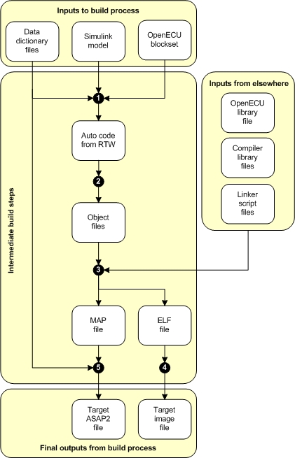
The build process has a number of inputs:
- Data dictionary files
The data dictionary files describe the data variables of the application code. Data variables are all C global variables, either RAM or ROM based. For each data variable which must be accessible from the calibration tool, there is a corresponding data dictionary element (DDE) which details attributes of the data variable, like description, type, units, and so on. See Section 4.2.2.2, “Data dictionary files”. for more.
The user must provide the data dictionaries.
- Simulink model
The application in model form. There are some restrictions on what the model can contain, see Section 4.3.1, “Block use restrictions”.
The user must provide the model.
- Simulink blockset
Supporting Simulink blocks which provide direct access to the ECU's functionality. OpenECU software provides the Simulink blockset. An overview of the blockset is given in Section 4.6, “OpenECU blockset features”.
- OpenECU library file
A compiler specific library file for OpenECU. The library file is linked with the application object files to create a binary image for execution on the target.
OpenECU software provides the library file.
- Compiler library file
The compiler's own support libraries (e.g., implementation of the C standard library or compiler specific extensions).
The compiler software provides the library file.
- Linker script files
The scripts tell the compiler how to combine the application object files, interface object files and libraries to create the binary image to run on the target ECU. This includes details about the layout of memory and how object file sections are allocated to memory.
OpenECU software provides the linker files.
The inputs are processed in a number of steps to create intermediate objects:
Runs RTW to generate C code from the Simulink model and DDEs. The generated C code includes the implementation of the model logic and any necessary code to bind the model with the OpenECU and compiler libraries.
Runs the compiler for the application code files. The compiler generates object files used in the link stage.
Runs the linker to combine the object files from the application and interface tool, as well as the compiler's library and OpenECU libraries, to generate an ELF file.
Runs support tools and scripts to extract a binary image of the application from the ELF file. At this stage, the binary image is modified with check-sums and auxiliary data to support robust operation on the ECU.
Runs support tools and scripts to generate an ASAP2 file from the target and DDE information. The ASAP2 file is used during reprogramming and calibration of the ECU.
From those intermediate steps, the final set of objects are created:
- Target ASAP2 file
An ASAP2 file details the memory areas used by the binary application image as well as how DDEs have been allocated to memory. The ASAP2 file is used by PC based tools to reprogram an ECU or to calibrate an ECU. See Section 4.5, “Programming an ECU” and Appendix B, Supporting tools for more.
- Target image file
The target image file contains the binary image of the application code and data. Once an ECU is programmed with the image file, the application can be executed. See Section 4.5, “Programming an ECU” for more.
To build the executable code for the ECU, select the model window so
it becomes focused then press CTRL+B to start the RTW build.
Alternatively, place a prtw_Build block in
the model and double click the block.
The build process starts by re-reading the build list to ensure the latest DDE information is present when generating the ASAP2 file.
### Starting Real-Time Workshop build procedure (with modification for OpenECU) for model:
Clearing any previously loaded build list...
Obtaining workspace data from each feature data dictionary...
Workspace variables loaded
The build then continues with the standard RTW build mechanism with a few additions for OpenECU. In some earlier versions of RTW, if this is the first time the model has been built, the build creates the RTW library which can take some minutes to complete. Subsequent builds of the same model skip this part of the build.
During the build, MATLAB will display a series of diagnostic and status messages with respect to the build. In MATLAB versions prior to r2014b, all messages will be logged to the main MATLAB console.
In MATLAB versions r2014b and later messages will be logged to The Diagnostic viewer window. This window can be viewed by clicking the link at the bottom of the model window.

If the build is successful, a number of files will be created:
model_name_tool_generic.a2l — the generic ASAP2 file for the build model;
model_name_tool_inca.a2l — the ETAS INCA specific ASAP2 file for the build model;
model_name_tool_vision.a2l — the ATI Vision specific ASAP2 file for the build model;
model_name_tool_canape.a2l — the Vector CANape specific ASAP2 file for the build model;
model_name_tool_vision.vst — the ATI Vision Strategy file for the build model (combined ASAP2 and S-record file — only generated if a compatible version of ATI Vision is installed, see the image generation options in Section 4.3.4, “Configuration options”);
model_name.a2l.err — any errors that resulted from creating the ASAP2 file (if there are any errors, a short extract is displayed at the end of the build);
model_name_image_small.s37 — the image bytes to program into the OpenECU in Motorola S-record format (small representing the minimum amount of code and data bytes to program the OpenECU device) — suitable for the ATI Vision calibration tool;
model_name_image_small.hex — the image bytes to program into the OpenECU in Intel HEX format — suitable for the Vector CANape calibration tool;
model_name.elf — the compiler's version of some of the above files — suitable for the PiSnoop development tool;
model_name.snx — lists of variables PiSnoop will show or hide automatically — suitable for the PiSnoop development tool;
where the text model_name denotes the name of your .mdl model file. Each of these files can be found in the same directory as your model file.
Note
A subset of these files can be produced by altering the OpenECU RTW options
(accessed by opening an OpenECU model and selecting the menu option
Simulation -> Simulation parameters... then browsing
to the OpenECU options under Real-Time Workshop.
More details on these settings are given in Section 4.3.4, “Configuration options”.
One of the ASAP2 files and one of the image files can now be used with a calibration tool to program the ECU via CCP (or if you are using a recent version of ATI Vision, you can simply use the strategy file).
Also at the end of a successful build, a short summary of the memory used by the model is displayed. It looks a little like:
Strategy memory:
 142696 bytes of strategy/code memory used
 250519 bytes remaining
Calibration memory:
   3376 bytes of calibration memory used (rough indication, includes Simulink support data)
 258767 bytes remaining
Workspace memory:
  14040 bytes of workspace/displayable memory used, including
    176 bytes of adaptive data, and
      2 bytes of diagnostic trouble code data, and
   8192 bytes of model stack
  24008 bytes remaining
Built at: 2005, 08, 02 (year, month, day) 10:52:47 (hour:min:sec)
but the values will vary based on your model.
- Strategy memory
Shows the amount of model code used and remaining.
- Calibration memory
Shows the amount of calibration data (as well as Simulink support data) used and remaining.
- Workspace memory
Shows the amount of used and remaining RAM, where RAM is used for general model calculations and signals, adaptive data and overall program stack.
As your model develops, it is useful to take regular snap shots of the
memory usage to determine how quickly development is using up memory
(and the same can be done by taking regular snap shots of the ASAP2
variables mpl_cpu_loaded and mpl_max_used_stack
to determine how quickly development is using up CPU resources).
There are a couple of sources of long build times.
- Building the RTW library source code
It can take some time to build the RTW sources, increasing in duration with increasing versions of MATLAB.
The commands to compile the RTW sources are easily recognisable during a build, where each source file that belongs to the RTW library starts with
rt_.dcc -@mk_rtw_cc_opts.cfg -o rt_atan2.o [path]\rt_atan2.c ...Versions of MATLAB after R2008a (inclusive) do not require the RTW library source code to be built in full and do not suffer from the larger compile times when building a model for the first time.
- Building the model source code
With versions of Diab 5.5.1.0 and later, larger models can take a significant amount of time to compile. This is due to a buffer size issue with the compiler. See Section 2.5.9.3, “Known issues” for a description of the work around to be used with the pcomp_CompileOptions block.
There are a couple of warnings and errors that occur more often than others and its worth reviewing those here:
- Cannot find the Diab compiler
An error message, similar to the following, indicates that the Diab compiler could not be found.
dcc -@mk_rtw_cc_opts.cfg -o [file-name].o [path to file].c
'dcc' is not recognized as an internal or external command,
operable program or batch file.
In order for the Diab compiler to run, the compiler must be installed and the the path to the compiler must be specified in one of two environment variables. See the instructions provided in the installation guide, Section 2.5, “Integration notes for third party tools”.
- Cannot run the Diab compiler
An error message, similar to any of the following, indicates that the Diab compiler cannot find a license.
fatal error (dcc:1635): License error: FLEXlm error:
      Cannot find license file (-1,73:2 "No such file or directory")
fatal error (dcc:1635): License error: FLEXlm error:
      No such feature exists (-5,357)
In order for the Diab compiler to run, it must have access to a valid license. The Diab compiler license is created by WindRiver after you purchase the compiler. If you run into trouble with your Diab compiler license, please contact OpenECU technical support and we will try to help out.
- Model too large for ECU memory space
An error message, similar to any of the following, indicates that the model has become too large for the target ECU.
dld -@mk_model_link_opts.cfg -@O=[model-name].map -o [model-name].elf
dld: '.' (0x[string]) is assigned invalid value: 0x[string]
The ECU has various memory spaces of finite size. If the model becomes too large to fit into these memory spaces, then the Diab linker will raise an error. It may be possible to optimise the build to reduce the final model size. Please contact OpenECU technical support and we will try to help out.
- Model uses absolute time
A warning message, similar to the following, indicates that the model uses absolute time.
### RTW build information:
Warning: the RTW generated code was found to contain calls to
         functions that access absolute time. See the OpenECU,
         Simulink and RTW documentation about absolute time,
         including a list of blocks that depend on absolute time.
         After a period of time, Simulink's absolute time will
         eventually saturate and blocks that use absolute time
         will fail to work correctly (including some functionality
         of blocks in triggered subsystems).
As part of the build process, OpenECU checks the Simulink/RTW generated code to determine if the model uses absolute time. Absolute time has some limitations, see Section 6.1.112, “Time (Simulink) (ptm_SimulinkTime)” for more.
In Figure 4.9, “System modes”, each of the major system modes is shown. When the ECU is turned on (or is recovering from a powered reset), the bootloader decides which major mode to enter based on external inputs to the ECU.
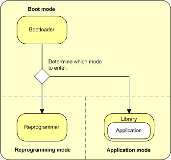
- Boot mode
Boot mode starts after reset, performs some tests and, if successful, determines what mode to enter (see Section 4.4.1, “Boot mode”).
- Reprogramming mode
Reprogramming mode is entered if the FEPS pin is asserted before the ECU is powered up, if there is an invalid application image in memory, or for certain targets if the ECU is running the application and allowing reprogramming while a reprogramming request is received (FEPS-less) (see Section 4.4.2, “Reprogramming mode”).
Entering reprogramming mode causes the ECU to listen to the communication buses for reprogramming instructions. The ECU does not run the application.
- Application mode
Application mode is entered if the FEPS pin is not asserted and if there is a valid application image in memory (see Section 4.4.3, “Application mode”).
Entering application mode causes the ECU to run the application. The ECU listens to the communications buses for reprogramming instructions, but the application can inhibit reprogramming from occurring if necessary.
When the ECU is turned on (or is recovering from a powered reset), the bootloader performs various tests. These include:
Tests on memory devices, looking for hard faults such as shorts on address lines, or memory locations which cannot hold their contents;
Tests on the code to run, looking for hard faults in the contents of code and data;
Tests on the frequency of reset, looking for unexpected resets which occur back to back in a short period of time.
If the tests fail then the bootloader will either reset or attempt to enter reprogramming mode, flashing a code to indicate the cause (see the technical specification for each ECU for details about code flashing). If the tests pass, then the bootloader will determine what mode to enter next (see Section 4.4.2, “Reprogramming mode” and Section 4.4.3, “Application mode” for details on how each mode is chosen).
When the ECU is turned on (or is recovering from a powered reset), the bootloader will enter reprogramming mode if the FEPS pin is asserted, if there is an invalid application image in memory, or for certain targets if the ECU is running the application and allowing reprogramming while a reprogramming request is received (FEPS-less).
In reprogramming mode, the ECU listens to the communications buses for instructions to reprogram, as described in Section 4.5, “Programming an ECU”.
When the ECU is turned on (or is recovering from a powered reset), the bootloader will enter application mode if the FEPS pin is not asserted and if there is a valid application image in memory.
When application mode is entered, the library initialises the ECU hardware and starts running the application model.
The platform performs various operations in the background including checks on RAM hardware. If a RAM error is detected, an unrecoverable error is raised (resulting in ECU reset) because program execution is otherwise likely to fail in an unpredictable manner.
Similarly non-volatile data is revalidated in the background and treated as if it is no longer available if validation fails. Thus if run-time memory corruption occurs affecting non-volatile data, any subsequent attempt to read that data will be handled in the same way as if the data were not present (default used instead).
Background checking for code or calibration corruption works through the Calibration Verification Number computation on supported targets with the OBD library option. Ensure that the CVN is recomputed continually if run-time corruption checking is required. If it is detected, an unrecoverable error is raised (resulting in ECU reset). This is in addition to boot-time checksum validation.
The OpenECU is programmed with any CCP compliant tool. Specific instructions for ATI Vision, Vector CANape and ETAS INCA calibration tools are provided in Appendix B, Supporting tools. If you have another CCP compliant tool, please refer to the manufacturer's instructions for further details in programming and refer to Appendix F, CCP compliance which details how OpenECU complies with the CCP 2.1 standard.
At a minimum, the OpenECU device will need to be powered and be connected to the CCP tool over CAN 0 or CAN A (whichever the target ECU makes available). In some cases the OpenECU module will need to have the FEPS line connected to a power supply capable of up to 19 volts (depending on target), as shown in the following diagram.
Note
The FEPS voltage must be asserted before the ECU is powered up. Powering the FEPS input and ECU simultaneously (i.e. shorting the FEPS and VPWR inputs) may result in reprogramming mode not being detected.
OpenECU operates in three system modes:
- Boot mode
This is the mode initiated when the ECU is turned on (or recovering from a powered reset). Boot mode choose whether to enter reprogramming mode or application mode.
- Reprogramming mode
This is the mode required to reprogram the OpenECU with the CCP tool. This mode is entered differently depending on the ECU. All OpenECU modules can be made to enter this mode by asserting the FEPS pin with a positive voltage (above the required threshold) and power cycling the OpenECU device.
- Application mode
This is the mode required to run the application on OpenECU. Start this mode by grounding the FEPS pin and power cycle the OpenECU device.
How reprogramming and application mode is entered differs slightly between groups of ECUs due to differences in the electronics. For the M220, M250, M460 and M461 targets, the next illustration shows how each mode is entered.
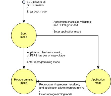
For the M221 and M670 targets, the next illustration shows how each mode is entered.
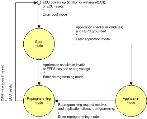
There are a number of ways in which an ECU can be reprogrammed:
- Reprogramming — ECU not previously programmed
Reprogramming the ECU without an application can be done with or without FEPS on the M110, M220, M221, M250, M460, M461 and M670.
Without a programmed application, reprogramming mode will use the default CCP settings as defined in Table 6.3, “CCP defaults”. As explained in the table, these settings will vary depending on the version of firmware that is programmed into the ECU.
- Reprogramming without FEPS — ECU previously programmed (M110, M220, M221, M250, M460, M461 and M670 only)
Once an M110, M220, M221, M250, M460, M461 or M670 ECU has been programmed with a valid application, that ECU can be reprogrammed without having to apply FEPS.
With a programmed application, reprogramming mode will use the CCP settings defined by the application already programmed. If an application with different CCP settings is programmed then the new CCP settings are used after the ECU is power cycled.
- Reprogramming with FEPS — ECU previously programmed (M220, M221, M250, M460, M461 and M670 only)
All OpenECU targets can be programmed by first applying FEPS and then cycling power to the ECU to enter reprogramming mode.
Furthermore, if the application is running and the application is not inhibiting programming then, without cycling power, the ECU can be programmed by applying FEPS and starting programming.
With a programmed application, reprogramming mode will use the CCP settings defined by the application already programmed. If an application with different CCP settings is programmed then the new CCP settings are used after the ECU is power cycled.
- Forced reprogramming with negative FEPS (M110, M220, M221, M250, M460, M461 and M670 only)
The M220, M221, M250, M460, M461 and M670 ECUs can be made to use the default CCP settings instead of the application settings by applying a negative voltage to FEPS and then cycling power to the ECU. Reprogramming mode will then use the default settings for CCP.
The defined CCP settings are defined in Table 6.3, “CCP defaults”. As explained in the table, these settings will vary depending on the version of firmware that is programmed into the ECU.
Once programmed, an ECU will remain in reprogramming mode until the power is cycled. After the power cycle, the ECU will determine which mode to enter based on the FEPS voltage. To start the application after programming, ensure FEPS is grounded and power cycle the ECU.
The FEPS pin is asserted by applying a voltage to the pin. The required voltage varies between ECUs.
Table 4.7. FEPS voltages
| M110 | M221 | M250 |
M220
M460 M461 M670 | Result |
|---|---|---|---|---|
| 0V | 0V | 0V | 0V | FEPS pin is grounded. On power up, the ECU attempts to run the last programmed application in application mode. If a application has not been programmed, the ECU enters reprogramming mode. |
| — | > +36V | > +13V | > +17V | FEPS pin is positive. On power up, the ECU enters reprogramming mode. If a application has previously been programmed, the ECU uses the CCP settings of the application. Otherwise, the ECU uses the default CCP settings. |
| < -16V | < -16V | < -18V | < -16V | FEPS pin is negative. On power up, the ECU enters reprogramming mode. The ECU uses the default CCP settings and ignores any CCP settings stored in any programmed application. |
As a shortcut, the device can be reprogrammed via a CCP compliant tool without cycling the power to the ECU (FEPS may or may not been to be applied depending on the ECU). When reprogramming starts, the OpenECU device switches from application mode to reprogramming mode. It may be undesirable to allow this method due to safety reasons, so the pcp_CCPInhibitReprogramming block can switch this method off.
If the OpenECU device has never been programmed before, it uses the CCP settings given in Table 6.3, “CCP defaults”. The CCP compliant tool must use the same settings. Once the OpenECU device has been reprogrammed with an application that uses different CCP settings, the CCP compliant tool must be changed to use these settings.
Certain OpenECU devices might require different protocols for programming than CCP such as J1939 or ISO 15765. Please consult the technical specification of your device to determine the supporting protocols.
The OpenECU blockset provides varied access to the features of both Simulink and the target ECU. The OpenECU blockset library groups common functionality together (as described in Section 4.1.5, “In MATLAB — Library browser (R2015a - R2020a)”):
OpenECU provides a series of blocks to store information across power cycles. The information can be stored in scalars, arrays or maps, and the scalars and maps can be adapted over time (for instance, when learning the mechanical end stops for valve positions over time). See Section 4.6.2, “Adaptive parameters” for details.
OpenECU provides a series of blocks to run an engine, including tracking synchronisation with crank and cam trigger wheels, measuring A/D inputs on an angle basis, and generating injector and coil/spark pulses. See Chapter 7, Angular detail for details.
OpenECU provides a series of communication blocks, which handle CAN, CCP (a calibration protocol over CAN), J1939 (an SAE protocol for vehicle communication) and basic signal checking. The blockset provides support for Vector CANdb files (which describe networks, CAN messages and CAN signals in detail). See Section 4.6.3, “Communications” for details.
OpenECU provides a series of blocks to adjust the compiler and linker options for a model build. Support for selecting which compiler to use as well as adjusting the options given to the compiler and linker allow some control when incorporating custom code and working around compiler bugs. See Section 4.6.4, “Compiler options” for details.
OpenECU has a mechanism for retiring old blocks and replacing them with more capable blocks through deprecation. See Section 4.6.5, “Deprecated blocks” for details.
OpenECU provides a series of blocks for fault and diagnostic trouble code logging. The fault information can be stored across power cycles and the diagnostic trouble codes can be automatically handled in some J1939 messaging. See Section 4.6.6, “Fault support” for details.
OpenECU provides a series of blocks for analogue and digital input processing. Support includes measuring analogue inputs, digital, frequency and PWM inputs. See Section 4.6.11, “Analogue and digital inputs”.
OpenECU provides a series of blocks to interact with the operating system The operating system schedules the different operations the ECU must perform to function correctly, including running the functionality assigned to each model rate. The blocks provide access to run-time schedule information, including how much processing time is taken up running all the software. See Section 4.6.13, “Operating system”.
OpenECU provides a series of blocks for analogue and digital output processing. Support includes driving constant current outputs, digital, PWM and stepper outputs. See Section 4.6.14, “Analogue and digital outputs”.
OpenECU provides a series of utility blocks to make some of the example models easier to use the first time around. These blocks can be incorporated in other models and provide quick mechanisms to configure each of the auto-coders, turn on and decode the sample time colours and build a model. See Section 4.6.15, “Real-Time Workshop (RTW) support”.
OpenECU provides a series of blocks to configure each of the target ECU specific features, not covered in a general sense by other groups of blocks. For instance, the blocks provide a mechanism to select whether some inputs are VRS single-ended or Hall effect and select the over-current trip level for some outputs. See Section 4.6.16, “Target ECU identification and configuration”.
OpenECU provides a series of blocks which provide timing information. Simulink maintains a base rate time, with a resolution as accurate as the quickest model rate. The ECU maintains a much higher resolution timer as well as access to the current time since power on. The blocks provide access to these timers. See Section 4.6.17, “Timing”.
OpenECU provides a series of blocks to perform common and general functions. These blocks are provided by OpenECU to support the same functionality across all versions of Simulink that OpenECU supports. See Section 4.6.18, “Utilities”.
OpenECU provides a series of blocks to access version information when using Simulink and when running the model on an ECU. For instance, there is a block to determine if the expected version of OpenECU is being used when editing the model, and a block to get the version of OpenECU software running an ECU. See Section 4.6.19, “Versioning”.
Calibratables and displayables are defined in a data dictionary, which can be set up per model. More details are given in Section 4.2.2.2, “Data dictionary files”.
OpenECU has specific support for ATI Vision, ETAS INCA and VECTOR CANape but can also generate generic ASAP2 information for inclusion into any ASAP2 compliant calibration tool.
The blockset library provides a series of blocks which allow the modeller to adjust scalars, 1-d and 2-d maps while the model is being iterated.
The blockset library provides access to non-volatile storage: storage retained when the power is removed from the module by either connecting a low power source to the Keep alive power pin to retain the contents of RAM storage, or by committing the data to Flash storage (see the technical specification for details on which storage type is supported by each target).
On start-up, the blockset library attempts to retrieve adaptive data prior to running the model application. While the application is running, the time at which the adaptive data is stored back to non-volatile memory is determined by the application itself.
The adaptive data is check-summed using a 16-bit CRC. Failure to match the check-sum against the adaptive data during library initialisation means that the data cannot be recovered. In this case, adaptive data is reverted to the default for each adaptive element (the defaults can be specified by the application).
There are two types of non-volatile memory dedicated to adaptive data:
- Battery backed RAM
Storage that requires an external power source when the ECU is powered down (not available on all target ECUs),
- Flash
Storage that requires no external power supply when the ECU is powered down (not available on all target ECUs).
See Section A.1, “ECU hardware reference documentation” for details of what non-volatile memory stores are available for each target ECU.
The application starts a commit of adaptive data to non-volatile store through the pnv_AdaptiveChecksum block.
Note
If the non-volatile memory store is Flash, then the library will halt the application while committing adaptive data to non-volatile memory. This is to prevent any higher-rate tasks interrupting and attempting to access the Flash device (which will generally be unavailable at that time).
The worst case scenario is for the application to be stopped for about 1.8 seconds. It is the responsibility of the application to ensure that there will be no detrimental side effects to stopping the application for this length of time, e.g., the application should ensure all coil and injector outputs are turned off if applicable for that ECU.
It should also be noted that, once started, it is not possible to interrupt the Flash commit process. So if, for example, a user of the ECU requests that the ECU start-up before the process has completed, the ECU will not try to start until control is passed back to the application.
The application can determine if the adaptive data requires a commit to non-volatile memory through the pnv_Status block. When the ECU decides to power down, if this block shows the data as unmodified there will be no need to store the data to non-volatile memory again; this is important for a Flash-based solution as this means there is no need to write the data to Flash, thus minimising shutdown time and reducing the number of Flash write cycles.
Functions to pack and transmit or receive and unpack CAN messages are provided. These functions also report status information, for example: bus off. User selectable data types for the message fields are supported at the Simulink block level.
Functions to use Vector CANdb files to define CAN messaging are provided:
Designed to work with ASAM (ASAP 1 and 2) compliant calibration tools. Data acquisition is at configurable rates for variables in the model, allowing the bandwidth available over CCP to be maximised. The CCP handler uses CAN transmit and receive functionality in the same way as the model (but these are largely hidden and not exposed through the model).
Functions to pack and transmit or receive and unpack J1939 messages are provided. User selectable data types for the message fields are supported at the Simulink block level.
Section 6.1.50, “J1939 configuration (pj1939_Configuration)”
Section 6.1.51, “J1939 channel configuration (pj1939_ChannelConfiguration)”
Section 6.1.59, “J1939 parameter group requested (pj1939_PgRequested)”
Section 6.1.58, “J1939 parameter group receive message (pj1939_PgReceive)”
Section 6.1.60, “J1939 parameter group transmit (pj1939_PgTransmit)”
Section 8.7.54, “J1939 send acknowledgement message (pj1939_SendAck)”
Functions to handle diagnostic messaging are provided:
Functions to help diagnose missing CAN signals are also provided:
Although not necessary in the majority of cases, it is sometimes useful to be able to modify the compiler or linker options while building a model. For instance, to turn on debug symbols, to turn off an optimisation which may be causing a problem, or to affect preprocessor conditions of hand written code included in the build.
Sometimes, as the functionality of a block changes, the change cannot be made without breaking the behaviour the model expects of the block. For instance, when a block has a couple of options replaced by a single option, the block cannot adjust itself when the model loads, and Simulink will print a series of error messages.
When this kind of change occurs, rather than change the existing block, a new block is created with the new functionality, while the old block is retained as is. This allows the model to load without Simulink printing errors and the model can be changed to use the new block as required.
However, to remove old functionality over time, the old block will be removed in a future version of the developer software, ensuring the blockset remains efficient. Blocks which are to be removed in the future are marked deprecated, and the documentation for those blocks indicates how to replace the block with an equivalent block that isn't marked deprecated.
Currently, the following blocks are marked deprecated and will be removed in a future version of the developer software. Please replace the use these blocks as soon as possible.
The block library provides support for Diagnostic Trouble Codes (DTCs), or fault indicators, which can be organised into a series of tables.
Section 6.1.38, “DTC diagnostic trouble code (pdtc_DiagnosticTroubleCode)”
Section 8.7.7, “DTC diagnostic trouble code (extended) (pdtc_DiagnosticTroubleCodeExt)”
Section 6.1.36, “DTC clear all if active (pdtc_ClearAllIfActive)”
Section 6.1.37, “DTC clear all if inactive (pdtc_ClearAllIfInactive)”
Section 8.7.12, “DTC table cleared indication (pdtc_TableCleared)”
and to provide simple signal checks:
The block library provides support for Parameter Identifiers (PIDs).
The block library provides support for freeze frames. Freeze frames capture pertinent operating conditions upon the occurrence of a fault. The platform supports freeze frames over the J1979 and J1939 protocols.
The block library provides support for service $09 InfoTypes.
The block library provides support for In-Use Performance Ratio (PPR).
The blockset library provides the mechanism for Simulink I/O blocks to access real hardware pins. There are a variety of general input blocks:
The functions work at the level of the micro-processor pin but the input and output circuitry of the ECU may change the characteristics of the signal. For instance, the input circuitry may include filtering or inversion. See the technical specification in Section A.1, “ECU hardware reference documentation” for a description of how the input and output circuitry works for an ECU.
There are two types of I/O on OpenECU hardware: direct and indirect I/O.
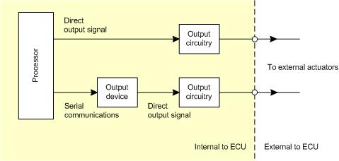
- Direct I/O
Direct I/O takes place on demand. The application calls the necessary function and the function takes a measurement or sets a driver accordingly.
- Indirect I/O
Indirect I/O is delayed.
For an input, the application calls the necessary function and the data to be read is taken from a buffer of data that was sampled some time ago. Once the model has completed each model rate once, the data is buffered at the quickest rate which requests the data. Thus indirect inputs are delayed by at most one iteration of the quickest rate which requests the input.
For an output, the application calls the necessary function and the data to be written is buffered and actioned some time later. Once the model has completed each model rate once, the buffered data is actioned at the quickest rate which writes the indirect output.
Indirect I/O always occurs when there is an device between the processor and the pin. The device communicates to the processor across a serial link and it is this communication which introduces the delay. Only I/O channels noted as serial in the technical specification (see Section A.1, “ECU hardware reference documentation”) are affected.
Each target ECU provides some measure of feedback for a subset of the output pins. For instance, measuring the reference voltage for A/D conversions to determine if the reference voltage generator has failed. A complete list of the monitors can be found in the technical specifications (see Section A.1, “ECU hardware reference documentation”). Each monitor is read by using one of the blocks, e.g., using the Section 6.1.5, “Analogue input — basic (pai_BasicAnalogInput)” block to read the analogue voltage of a monitor.
Wide band sensors (often referred to as UEGO sensors, for Universal Exhaust Gas Oxygen, or linear lambda oxygen sensor) generate an indication of the oxygen content in the exhaust gas mixture. Some modules provide UEGO inputs processed by Bosch CJ125 ASICs. The OpenECU platform provides an interface to control the CJ125 device:
UEGO sensors require careful control of the heating element to avoid damaging the ceramic heater, and careful control of the pump cell current to accurately measure the oxygen content. See the modules technical specification document for more details.
- Task Scheduling
The Real-Time Operating System (RTOS) schedules tasks to a resolution of 1 millisecond. Portions of the model which run at the same rate, are gathered together into tasks which are each assigned a unique priority and are fully pre-emptive. The priority of each task is assigned according to model rate (quickest rate is assigned the highest priority) with the angular rate (if enabled in the RTW options) assigned the highest priority. Tasks are also set up to handle CCP communications; polling for received CAN messages and software queuing for CAN transmit messages.
The blockset library provides access to information about the tasks at run time:
Some operations are performed in parallel on different devices to the processor that runs tasks. On some target ECU, information is available about how heavily loaded these devices are:
If enabled, OpenECU interprets the fastest rate task defined in the Simulink model as a task that is triggered at specific engine angles if the check-box 'Angular Rate Functionality' is checked. This check-box can be found in the menu option Simulation Parameters -> Real Time Workshop -> OpenECU code generation options. The following screen is an example:
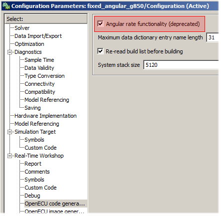
The angular task is run at the engine angles defined in the engine configuration block, i.e. the TDC angle + Angular Task Calc Angle. The angular task is intended for calculating values such as the fuelling per cylinder. Note that if the engine is not rotating, the angular task will not execute. In simulation, the angular task will behave as the fastest rate task and all other task time-steps must be a multiple of the angular task time-step. A figure of 0.001s is suggested for the angular task time-step.
- Stack
Each task shares the same stack space, an area of RAM dedicated to storing temporary information about the task and the functionality the task is performing. The amount of stack space is finite and must be specified when the model is built. The blockset library provides information about how much stack has be used since ECU power on or last reset:
- Watchdog
Each ECU implements a watchdog, a mechanism to reset the ECU if the ECU software appears to be misbehaving. A simple watchdog scheme is implemented by the platform software but the application model can take control of the watchdog and implement a more complex scheme.
- Memory tests
Each ECU implements an internal memory test during startup to check for hard memory faults. Hard memory faults are memory faults that have become permanent such as a shorted address line, or a memory cell that cannot change state. RAM is tested by performing a destructive walking one's test on the address and data lines and a memory recall test on the memory cells. ROM is tested by calculating a checksum of the contents. If a hard memory fault is detected, then the ECU will reset itself to force safety related outputs to a default state.
Some ECUs also implement a continuous internal memory test during runtime to check for soft memory faults. Soft memory faults are transient memory faults, such as might occur when a memory cell changes state due to stray electron releases. The error correction module hardware is capable of detecting and correcting errors that are limited to a single bit wrong in a 64-bit double word. If more than one bit is wrong in a 64-bit double word, then the hardware can detect the error, but it cannot be corrected. If an uncorrectable soft memory fault is detected, then the ECU will reset itself to force safety related outputs to a default state.
The blockset library provides Simulink blocks to report the status of the continuous internal memory soft error test as well as the address of the last detected correctable error.
The framework of OpenECU requires application processing to occur in one or more tasks. These tasks are declared in the interface specification file, each declaring an application function to call and a priority to schedule the task relative to others.
In order to support the services provided by the library (e.g., J1939 messaging), the library defines a number of auxiliary tasks. These tasks have a unique priority relative to each other and the application tasks, as shown in Table 4.8, “Library and application tasks”.
Table 4.8. Library and application tasks
| Priority | Task | Trigger | Targets | Description |
|---|---|---|---|---|
| 20+n | Module protection task | 10ms periodic | M220, M221, M250, M460, M461, and M670 | Handles protection mechanisms to avoid ECU damage. |
| 19+n | TPU task | Sporadic | M220, M221, M250, and M670 | Handles the event processing required of the TPU peripheral on some ECUs. |
| 18+n | Power management task | 100ms periodic | M221 and M670 | Handles the power hold processing on some ECUs. |
| 17+n | Flash code task | 100ms periodic | M220, M221, M250, M460, M461, and M670 | Handles the Flash code output pin on some ECUs. |
| 16+n | High-Side ASIC task | 100ms periodic | M670 | Handles the high side output pin(s) on some ECUs. |
| 15+n | SPI messaging task | Sporadic | M220, M221, M250, M460, M461, and M670 | Handles SPI messaging between peripherals on-board the ECU. |
| 14+n | CAN messaging (event) task | 2ms periodic burst | All | Handles CAN messaging. |
| 13+n | J1939 messaging task | 5ms periodic | All | Handles J1939 messaging. |
| 12+n | PFF task | 10ms periodic | All | Handles freeze frame processing. |
| 11+n | PFS task | 10ms periodic | All | Handles non-volatile filesystem. |
| 10+n | PISO messaging task | 5ms periodic | All | Handles ISO-15765 messaging. |
| 9+n | PDG messaging task | 10ms periodic | All | Handles ISO-15765 based diagnostics messaging. |
| 8+n | Application crank sync-point trigger task | Angular | M220, M221, M250 and M670 | Handles crank synchronous sync-point processing. |
| 7+n | Application TDC-calculation task | Angular | M220, M221, M250 and M670 | Handles engine synchronous TDC-calculation processing. |
| 6..6+n | Application tasks | Periodic | All | Handles application processing. |
| 5 | PDTC task | 100ms | All | Handles diagnostic trouble code processing. |
| 4 | CAN messaging task | 2ms periodic burst | All | Handles CAN messaging. |
| 3 | SPI task | 1000ms periodic | M220, M221, M250, M460, M461, and M670 | Handles SPI messaging utility functions. |
| 2 | Watchdog task | 200ms periodic | All | Handles the processor watchdog. |
| 1 | CCP task | 5ms periodic | All | Handles the CAN Calibration Protocol messaging to and from the calibration tool. |
Tasks can have different triggers. Triggers make the task become ready to run. The highest priority task ready to run is given the CPU.
- Sporadic
The task becomes ready to run based on an event. The event is generally not periodic, but may be periodic under some conditions.
- Angular
The task becomes ready to run based on the crank or engine position. See Chapter 7, Angular detail for more about supported engine functionality.
- Periodic
The task becomes ready to run on a periodic basis.
- Periodic (burst)
The task becomes ready to run based on an event. Once ready, the task becomes periodic for a number of iterations, before stopping and waiting for another event.
Note
The scheduler deals with both application and library tasks. It is possible for a high priority application task to use the processor for as long as it needs and there is no protection offered by the library to prevent tasks from using up more processor time than they should.
The application tasks are scheduled to relative to the library tasks such that a long running task may cause a lower priority library task to become unduly delayed.
An example of this would be the CCP task which runs every 5ms. It is conceivable that an application task may take longer than 5ms to complete and that is a desirable property of the application. However, when the application task takes longer than 5ms, the CCP task becomes delayed by the application task.
The design of the library tries to mitigate the consequences of delayed library tasks. Delaying the library CCP task may cause a burst of DAQ messages to the calibration tool to become delayed and the calibration tool may complain, but delaying the CCP task will not cause the I/O functionality to become delayed or mis-behave.
However, mitigation is all that the library can achieve if the application uses large amounts of the processor, and, for this reason the design of the application must take this into account by keeping the application tasks short. For instance, by splitting long running tasks up into discrete parts which are scheduled on successive task invocations.
The blockset library provides the mechanism for Simulink I/O blocks to access real hardware pins. There are a variety of general output blocks:
Section 6.1.84, “PWM output — fixed frequency (pdx_PWMOutput)”
Section 6.1.107, “PWM output — variable frequency, synchronised (pdx_PWMSynchronisedOutput)”
Section 6.1.85, “PWM output — variable frequency (pdx_PWMVariableFrequencyOutput)”
Section 6.1.73, “Peak and hold injector output (pdx_PeakHoldInjectorOutput)”
as well as a way to control the overall status of the output drivers:
and a way to diagnose the status of the electrical connections of some ECU loads:
The functions work at the level of the micro-processor pin but the input and output circuitry of the ECU may change the characteristics of the signal. For instance, the input circuitry may include filtering or inversion. See the technical specification in Section A.1, “ECU hardware reference documentation” for a description of how the input and output circuitry works for an ECU.
There are two types of I/O on OpenECU hardware: direct and indirect I/O.
- Direct I/O
Direct I/O takes place on demand. The application calls the necessary function and the function takes a measurement or sets a driver accordingly.
- Indirect I/O
Indirect I/O is delayed. The application calls the necessary function but the data to be read or set is actioned some time after the function returns.
Indirect I/O always occurs when there is an device between the processor and the pin. The device communicates to the processor across a serial link and it is this communication which introduces the delay. Only I/O channels noted as serial in the technical specification (see Section A.1, “ECU hardware reference documentation”) are affected.
Each target ECU provides some measure of feedback for a subset of the output pins. For instance, measuring the reference voltage for A/D conversions to determine if the reference voltage generator has failed. A complete list of the monitors can be found in the technical specifications (see Section A.1, “ECU hardware reference documentation”). Each monitor is read by using one of the OpenECU blocks to read the monitoring state of an output. For instance, using the pdx_DigitalInput block to read one of the digital state monitors, or the pai_BasicAnalogInput block to read one of the voltage monitors.
RTW creates software tasks for each rate in the model, and Simulink can colour each block in the model based on the rate of the block. This can make it easier to understand what parts of the model run at which rate, and to understand how information is passed between rates.
To support switching between auto-coders, the blockset library provides a set of blocks which switch between the different configuration sets. Simulink configuration sets contain options for a specific auto-coder. Currently, building models against the RTW (GRT RTMODEL) and RTW (EC) auto-coders is supported.
The blockset provides a utility block to start a model build. Pressing CTRL+B in a model window performs the same functionality.
All ECUs supported by OpenECU have a common subset of functionality, which applies equally to all ECUs.
Some ECUs have capabilities which don't fit into the standard framework, and special support is provided for those capabilities.
Real time applications, like those developed for OpenECU, often need to time events or durations, at different resolutions. The blockset library provides two mechanisms to manipulate time: using the Simulink task timers; and using the ECU processor's timers.
The I/O library also provides a number of support or utility functions to facilitate module configuration and diagnosis:
map look-up and interpolation:
signal conditioning:
For configuration management purposes, it can be useful to restrict the version of developer software that can be used when editing and building a model. The blockset library provides a flexible way to specify the allowable versions.
For configuration management and debugging purposes, it can be useful to know the versions of software running on an ECU are compatible. The blockset library provides a way to retrieve the version numbers of the various software components running on an ECU.
And a way to retrieve the date that each of those software components was built.
A way to ensure the code and calibration memory regions have not been altered is provided.
Existing models, not created with the OpenECU oe_create_model,
command can be converted to run with OpenECU with some effort. Some models which
already follow some of the guidelines set out in Chapter 5, Design and modelling
will be easier to convert than others.
When converting any model, you will need to consider the following changes (as well as those in Section 4.3.1, “Block use restrictions”):
Note
Some of the settings are harder to configure than others. It may be easier overall to create a new model using the:
oe_create_modelcommand and copying the systems and blocks to this new model.
- Simulink model simulation settings
The OpenECU build mechanism relies on particular settings for the model, e.g., that it can be solved with a discrete solver not a continuous one. The following simulation settings should be configured when converting any model for R2015a.
Table 4.9. Model simulation settings for R2015a
Tab Item Parameter Setting Solver Simulation time Stop time It's a good idea to set the stop time to some large number (e.g. inf) so that your simulation doesn't stop unexpectedly when you're testing it (this value is ignored when the model is built and run on target).Solver options Type OpenECU runs the model at regular periodic intervals, so set to Fixed-step. Solver And OpenECU is a discrete controller, so set the solver to discrete (not continuous states). Fixed step size Set to auto to allow the Simulink solver find the quickest model rate. Tasking and sample time options Periodic sample time constraint Set to Unconstrained. Tasking mode for periodic sample times Set to auto. Automatically handle data transfers between tasks Set to off. Higher priority value indicates higher task priority Set to on. Optimisation Simulation and code generation Block reduction Set to off. Implement logic signals as boolean data Set to on to save RAM usage on the target ECU (but OpenECU will work with this parameter set to off). Use integer division to handle net slopes that are reciprocals of integers Set to off. Use floating-point multiplication to handle net slope corrections Set to off. Conditional input branch execution Set to on to help improve switch and multiport switch block execution. Application lifespan Set to inf. Data initialisation Use memset to initialise floats and doubles to 0.0 Set to on to improve code space. Integer and fixed-point Remove code from floating-point to integer conversions that wraps ... Set to off Remove code from floating-point to integer conversions with saturation ... Set to on Accelerating simulations Compiler optimisation level Set to Optimizations off (faster builds) Verbose accelerator builds Set to off Signals and Parameters >> Simulation and code generation Inline parameters Set to on so that signals can be calibrated. Signal storage reuse Set to on to save RAM usage. Signals and Parameters >> Code generation Enable local block outputs Set to on. Eliminate superfluous temporary variables Set to on Minimize data copies between local and global variables Set to on Reuse block outputs Set to on Inline invariant signals Set to on Use memcpy for vector assignment Set to on to improve code space Memcpy threshold Set to 64 Loop unrolling threshold Set to 5 Maximum stack size (bytes) Set to Inherit from target Stateflow Use bitsets for storing state configuration Set to off Use bitsets for storing Boolean data Set to off Hardware implementation Embedded hardware Device vendor Set to Freescale. Device type Set to 32-bit PowerPC. Emulation hardware None Set to off so that you can change the device type. Device vendor Set to Freescale. Device type Set to 32-bit PowerPC. Code Generation Target selection System target file Set to openecu.tlc. Build options Template makefile Set to openecu_r2015a.tmf (note that this option is automatically set at the start of each build based on the version of Simulink running). Code Generation > Interface Code Interface Classic Call Interface Set to on (note: this option only appears when building for an RTModel configuration).
or the following simulation settings for R2015b:
Table 4.10. Model simulation settings for R2015b
Tab Item Parameter Setting Solver Simulation time Stop time It's a good idea to set the stop time to some large number (e.g. inf) so that your simulation doesn't stop unexpectedly when you're testing it (this value is ignored when the model is built and run on target).Solver options Type OpenECU runs the model at regular periodic intervals, so set to Fixed-step. Solver And OpenECU is a discrete controller, so set the solver to discrete (not continuous states). Fixed step size Set to auto to allow the Simulink solver find the quickest model rate. Tasking and sample time options Periodic sample time constraint Set to Unconstrained. Tasking mode for periodic sample times Set to auto. Automatically handle data transfers between tasks Set to off. Higher priority value indicates higher task priority Set to on. Optimisation Simulation and code generation Block reduction Set to off. Implement logic signals as boolean data Set to on to save RAM usage on the target ECU (but OpenECU will work with this parameter set to off). Use integer division to handle net slopes that are reciprocals of integers Set to off. Use floating-point multiplication to handle net slope corrections Set to off. Conditional input branch execution Set to on to help improve switch and multiport switch block execution. Application lifespan Set to inf. Data initialisation Use memset to initialise floats and doubles to 0.0 Set to on to improve code space. Integer and fixed-point Remove code from floating-point to integer conversions that wraps ... Set to off Remove code from floating-point to integer conversions with saturation ... Set to on Accelerating simulations Compiler optimisation level Set to Optimizations off (faster builds) Verbose accelerator builds Set to off Signals and Parameters >> Simulation and code generation Inline parameters Set to on so that signals can be calibrated. Signal storage reuse Set to on to save RAM usage. Signals and Parameters >> Code generation Enable local block outputs Set to on. Eliminate superfluous temporary variables Set to on Minimize data copies between local and global variables Set to on Reuse block outputs Set to on Inline invariant signals Set to on Use memcpy for vector assignment Set to on to improve code space Memcpy threshold Set to 64 Loop unrolling threshold Set to 5 Maximum stack size (bytes) Set to Inherit from target Stateflow Use bitsets for storing state configuration Set to off Use bitsets for storing Boolean data Set to off Hardware implementation Embedded hardware Device vendor Set to Freescale. Device type Set to 32-bit PowerPC. Emulation hardware None Set to off so that you can change the device type. Device vendor Set to Freescale. Device type Set to 32-bit PowerPC. Code Generation Target selection System target file Set to openecu.tlc. Build options Template makefile Set to openecu_r2015b.tmf (note that this option is automatically set at the start of each build based on the version of Simulink running). Code Generation > Interface Code Interface Classic Call Interface Set to on (note: this option only appears when building for an RTModel configuration).
or the following simulation settings for R2016a:
Table 4.11. Model simulation settings for R2016a
Tab Item Parameter Setting Solver Simulation time Stop time It's a good idea to set the stop time to some large number (e.g. inf) so that your simulation doesn't stop unexpectedly when you're testing it (this value is ignored when the model is built and run on target).Solver options Type OpenECU runs the model at regular periodic intervals, so set to Fixed-step. Solver And OpenECU is a discrete controller, so set the solver to discrete (not continuous states). Fixed step size Set to auto to allow the Simulink solver find the quickest model rate. Tasking and sample time options Periodic sample time constraint Set to Unconstrained. Tasking mode for periodic sample times Set to auto. Show concurrent execution options Set to off. Allow tasks to execute concurrently on target Set to off. Automatically handle data transfers between tasks Set to off. Higher priority value indicates higher task priority Set to on. Optimisation Simulation and code generation Block reduction Set to off. Implement logic signals as boolean data Set to on to save RAM usage on the target ECU (but OpenECU will work with this parameter set to off). Use integer division to handle net slopes that are reciprocals of integers Set to off. Use floating-point multiplication to handle net slope corrections Set to off. Conditional input branch execution Set to on to help improve switch and multiport switch block execution. Application lifespan Set to inf. Data initialisation Use memset to initialise floats and doubles to 0.0 Set to on to improve code space. Integer and fixed-point Remove code from floating-point to integer conversions that wraps ... Set to off Remove code from floating-point to integer conversions with saturation ... Set to on Accelerating simulations Compiler optimisation level Set to Optimizations off (faster builds) Verbose accelerator builds Set to off Signals and Parameters >> Simulation and code generation Inline parameters Set to on so that signals can be calibrated. Signal storage reuse Set to on to save RAM usage. Signals and Parameters >> Code generation Enable local block outputs Set to on. Eliminate superfluous temporary variables Set to on Minimize data copies between local and global variables Set to on Reuse block outputs Set to on Inline invariant signals Set to on Use memcpy for vector assignment Set to on to improve code space Memcpy threshold Set to 64 Loop unrolling threshold Set to 5 Maximum stack size (bytes) Set to Inherit from target Stateflow Use bitsets for storing state configuration Set to off Use bitsets for storing Boolean data Set to off Hardware implementation Embedded hardware Device vendor Set to Freescale. Device type Set to 32-bit PowerPC. Emulation hardware None Set to off so that you can change the device type. Device vendor Set to Freescale. Device type Set to 32-bit PowerPC. Code Generation Target selection System target file Set to openecu.tlc. Build options Template makefile Set to openecu_r2016a.tmf (note that this option is automatically set at the start of each build based on the version of Simulink running). Code Generation > Interface Code Interface Classic Call Interface Set to on (note: this option only appears when building for an RTModel configuration).
or the following simulation settings for R2016b:
Table 4.12. Model simulation settings for R2016b
Tab Item Parameter Setting Solver Simulation time Stop time It's a good idea to set the stop time to some large number (e.g. inf) so that your simulation doesn't stop unexpectedly when you're testing it (this value is ignored when the model is built and run on target).Solver options Type OpenECU runs the model at regular periodic intervals, so set to Fixed-step. Solver And OpenECU is a discrete controller, so set the solver to discrete (not continuous states). Fixed step size Set to auto to allow the Simulink solver find the quickest model rate. Tasking and sample time options Periodic sample time constraint Set to Unconstrained. Tasking mode for periodic sample times Set to auto. Automatically handle data transfers between tasks Set to off. Higher priority value indicates higher task priority Set to on. Optimisation Simulation and code generation Block reduction Set to off. Implement logic signals as boolean data Set to on to save RAM usage on the target ECU (but OpenECU will work with this parameter set to off). Use integer division to handle net slopes that are reciprocals of integers Set to off. Use floating-point multiplication to handle net slope corrections Set to off. Conditional input branch execution Set to on to help improve switch and multiport switch block execution. Application lifespan Set to inf. Data initialisation Use memset to initialise floats and doubles to 0.0 Set to on to improve code space. Integer and fixed-point Remove code from floating-point to integer conversions that wraps ... Set to off Remove code from floating-point to integer conversions with saturation ... Set to on Accelerating simulations Compiler optimisation level Set to Optimizations off (faster builds) Verbose accelerator builds Set to off Signals and Parameters >> Simulation and code generation Inline parameters Set to on so that signals can be calibrated. Signal storage reuse Set to on to save RAM usage. Signals and Parameters >> Code generation Enable local block outputs Set to on. Eliminate superfluous temporary variables Set to on Minimize data copies between local and global variables Set to on Reuse block outputs Set to on Inline invariant signals Set to on Use memcpy for vector assignment Set to on to improve code space Memcpy threshold Set to 64 Loop unrolling threshold Set to 5 Maximum stack size (bytes) Set to Inherit from target Stateflow Use bitsets for storing state configuration Set to off Use bitsets for storing Boolean data Set to off Hardware implementation Embedded hardware Device vendor Set to Freescale. Device type Set to 32-bit PowerPC. Emulation hardware None Set to off so that you can change the device type. Device vendor Set to Freescale. Device type Set to 32-bit PowerPC. Code Generation Target selection System target file Set to openecu.tlc. Build options Template makefile Set to openecu_r2016b.tmf (note that this option is automatically set at the start of each build based on the version of Simulink running). Code Generation > Interface Code Interface Classic Call Interface Set to on (note: this option only appears when building for an RTModel configuration).
or the following simulation settings for R2017a:
Table 4.13. Model simulation settings for R2017a
Tab Item Parameter Setting Solver Simulation time Stop time It's a good idea to set the stop time to some large number (e.g. inf) so that your simulation doesn't stop unexpectedly when you're testing it (this value is ignored when the model is built and run on target).Solver options Type OpenECU runs the model at regular periodic intervals, so set to Fixed-step. Solver And OpenECU is a discrete controller, so set the solver to discrete (not continuous states). Fixed step size Set to auto to allow the Simulink solver find the quickest model rate. Tasking and sample time options Periodic sample time constraint Set to Unconstrained. Tasking mode for periodic sample times Set to auto. Automatically handle data transfers between tasks Set to off. Higher priority value indicates higher task priority Set to on. Optimization Simulation and code generation Use integer division to handle net slopes that are reciprocals of integers Set to off. Use floating-point multiplication to handle net slope corrections Set to off. Application lifespan Set to inf. Integer and fixed-point Remove code from floating-point to integer conversions that wraps ... Set to off Advanced parameters Compiler optimisation level Set to Optimizations off (faster builds) Verbose accelerator builds Set to off Block reduction Set to off. Signal storage reuse Set to on to save RAM usage. Conditional input branch execution Set to on to help improve switch and multiport switch block execution. Implement logic signals as boolean data Set to on to save RAM usage on the target ECU (but OpenECU will work with this parameter set to off). Remove code from floating-point to integer conversions with saturation ... Set to on Use memset to initialise floats and doubles to 0.0 Set to on to improve code space. Optimization > Signals and Parameters Code generation Default parameter behavior Inline parameters Set to Inlined so that signals can be calibrated. Inline invariant signals Set to on Use memcpy for vector assignment Set to on to improve code space Memcpy threshold Set to 64 Loop unrolling threshold Set to 5 Maximum stack size (bytes) Set to Inherit from target Enable local block outputs Set to on. Reuse block outputs Set to on Eliminate superfluous temporary variables Set to on Optimization > Stateflow Stateflow Use bitsets for storing state configuration Set to off Use bitsets for storing Boolean data Set to off Hardware implementation Embedded hardware Device vendor Set to Freescale. Device type Set to 32-bit PowerPC. Code Generation Target selection System target file Set to openecu_grt.tlc. Build process Template makefile Set to openecu_grt_r2018b_64.tmf (note that this option is automatically set at the start of each build based on the version of Simulink running). Code Generation > Interface Advanced parameters Classic Call Interface Set to on (note: this option only appears when building for an RTModel configuration).
or the following simulation settings for R2017b:
Table 4.14. Model simulation settings for R2017b
Tab Item Parameter Setting Solver Simulation time Stop time It's a good idea to set the stop time to some large number (e.g. inf) so that your simulation doesn't stop unexpectedly when you're testing it (this value is ignored when the model is built and run on target).Solver options Type OpenECU runs the model at regular periodic intervals, so set to Fixed-step. Solver And OpenECU is a discrete controller, so set the solver to discrete (not continuous states). Fixed step size Set to auto to allow the Simulink solver find the quickest model rate. Tasking and sample time options Periodic sample time constraint Set to Unconstrained. Tasking mode for periodic sample times Set to auto. Automatically handle data transfers between tasks Set to off. Higher priority value indicates higher task priority Set to on. Optimization Simulation and code generation Use integer division to handle net slopes that are reciprocals of integers Set to off. Use floating-point multiplication to handle net slope corrections Set to off. Application lifespan Set to inf. Integer and fixed-point Remove code from floating-point to integer conversions that wraps ... Set to off Advanced parameters Compiler optimisation level Set to Optimizations off (faster builds) Verbose accelerator builds Set to off Block reduction Set to off. Signal storage reuse Set to on to save RAM usage. Conditional input branch execution Set to on to help improve switch and multiport switch block execution. Implement logic signals as boolean data Set to on to save RAM usage on the target ECU (but OpenECU will work with this parameter set to off). Remove code from floating-point to integer conversions with saturation ... Set to on Use memset to initialise floats and doubles to 0.0 Set to on to improve code space. Optimization > Signals and Parameters Code generation Default parameter behavior Inline parameters Set to Inlined so that signals can be calibrated. Inline invariant signals Set to on Use memcpy for vector assignment Set to on to improve code space Memcpy threshold Set to 64 Loop unrolling threshold Set to 5 Maximum stack size (bytes) Set to Inherit from target Enable local block outputs Set to on. Reuse block outputs Set to on Eliminate superfluous temporary variables Set to on Optimization > Stateflow Stateflow Use bitsets for storing state configuration Set to off Use bitsets for storing Boolean data Set to off Hardware implementation Embedded hardware Device vendor Set to Freescale. Device type Set to 32-bit PowerPC. Code Generation Target selection System target file Set to openecu_grt.tlc. Build process Template makefile Set to openecu_grt_r2018b_64.tmf (note that this option is automatically set at the start of each build based on the version of Simulink running). Code Generation > Interface Advanced parameters Classic Call Interface Set to on (note: this option only appears when building for an RTModel configuration).
or the following simulation settings for R2018a or R2018b:
Table 4.15. Model simulation settings for R2018a and R2018b
Tab Item Parameter Setting Solver Simulation time Stop time It's a good idea to set the stop time to some large number (e.g. inf) so that your simulation doesn't stop unexpectedly when you're testing it (this value is ignored when the model is built and run on target).Solver selection Type OpenECU runs the model at regular periodic intervals, so set to Fixed-step. Solver And OpenECU is a discrete controller, so set the solver to discrete (not continuous states). Solver details Fixed step size Set to auto to allow the Simulink solver find the quickest model rate. Tasking and sample time options Periodic sample time constraint Set to Unconstrained. Treat each discrete rate as a separate task Set to on. Allow tasks to execute concurrently on target Set to off. Automatically handle rate transition for data transfer Set to off. Higher priority value indicates higher task priority Set to on. Math and Data Types Basic parameters Default for underspecified data type: Set to double. Use division for fixed-point net slope computation: Set to off. Use floating-point multiplication to handle net slope corrections Set to off. Use algorithms optimized for row-major array layout Set to off. Application lifespan Set to inf. Advanced parameters Implement logic signals as boolean data (vs. double) Set to on to save RAM usage on the target ECU (but OpenECU will work with this parameter set to off). Hardware implementation Embedded hardware Hardware board: Set to Determined by Code Generation system target file.. Device vendor Set to Freescale. Device type Set to 32-bit PowerPC. Simulation Target Advanced parameters Block reduction Set to off. Compiler optimization level Set to Optimizations off (faster builds) Conditional input branch execution Set to on to help improve switch and multiport switch block execution. Signal storage reuse Set to on to save RAM usage. Verbose accelerator builds Set to off Code Generation Target selection System target file Set to openecu_grt.tlc. (Note that this changes the active configuration, changes to other configurations are not automatically applied to this one.) Build process Generate makefile Set to on. Template makefile Set to openecu_grt_r2018a_64.tmf or openecu_grt_r2018b_64.tmf (note that this option is automatically set at the start of each build based on the version of Simulink running). Make command Set to make_rtw. Code Generation > Optimization Basic parameters Default parameter behavior Set to Inlined so that signals can be calibrated. Use memcpy for vector assignment Set to on to improve code space Memcpy threshold Set to 64 Loop unrolling threshold Set to 5 Maximum stack size (bytes) Set to Inherit from target Advanced parameters Inline invariant signals Set to on Enable local block outputs Set to on. Reuse block outputs Set to on Eliminate superfluous temporary variables Set to on Remove code from floating-point to integer conversions with saturation ... Set to on Use memset to initialise floats and doubles to 0.0 Set to on to improve code space. Remove code from floating-point to integer conversions that wraps ... Set to off Advanced parameters > Stateflow Use bitsets for storing state configuration Set to off Use bitsets for storing Boolean data Set to off Code Generation > Interface Advanced Classic Call Interface Set to on (note: this option only appears when building for an RTModel configuration).
or the following simulation settings for R2019a, R2019b, or R2020a:
Table 4.16. Model simulation settings for R2019a, R2019b, and R2020a
Tab Item Parameter Setting Solver Simulation time Stop time It's a good idea to set the stop time to some large number (e.g. inf) so that your simulation doesn't stop unexpectedly when you're testing it (this value is ignored when the model is built and run on target).Solver selection Type OpenECU runs the model at regular periodic intervals, so set to Fixed-step. Solver And OpenECU is a discrete controller, so set the solver to discrete (not continuous states). Solver details Fixed step size Set to auto to allow the Simulink solver find the quickest model rate. Tasking and sample time options Periodic sample time constraint Set to Unconstrained. Treat each discrete rate as a separate task Set to on. Allow tasks to execute concurrently on target Set to off. Automatically handle rate transition for data transfer Set to off. Higher priority value indicates higher task priority Set to on. Math and Data Types Basic parameters Default for underspecified data type: Set to double. Use division for fixed-point net slope computation: Set to off. Use floating-point multiplication to handle net slope corrections Set to off. Use algorithms optimized for row-major array layout Set to off. Application lifespan Set to inf. Advanced parameters Implement logic signals as boolean data (vs. double) Set to on to save RAM usage on the target ECU (but OpenECU will work with this parameter set to off). Hardware implementation Embedded hardware Hardware board: Set to Determined by Code Generation system target file.. Device vendor Set to Freescale. Device type Set to 32-bit PowerPC. Simulation Target Advanced parameters Block reduction Set to off. Compiler optimization level Set to Optimizations off (faster builds) Conditional input branch execution Set to on to help improve switch and multiport switch block execution. Signal storage reuse Set to on to save RAM usage. Verbose accelerator builds Set to off Code Generation Target selection System target file Set to openecu_grt.tlc. (Note that this changes the active configuration, changes to other configurations are not automatically applied to this one.) Build process Toolchain Set to OpenECU Diab 5.9 | gmake (64-bit Windows). (Note the toolchain is updated automatically by the Compiler option.) Build configuration Set to Faster Builds (Note the options Faster Builds, Faster Runs, and Debug are identical). Code Generation > Optimization Basic parameters Default parameter behavior Set to Inlined so that signals can be calibrated. Use memcpy for vector assignment Set to on to improve code space Memcpy threshold Set to 64 Loop unrolling threshold Set to 5 Maximum stack size (bytes) Set to Inherit from target Advanced parameters Inline invariant signals Set to on Enable local block outputs Set to on. Reuse block outputs Set to on Eliminate superfluous temporary variables Set to on Remove code from floating-point to integer conversions with saturation ... Set to on Use memset to initialise floats and doubles to 0.0 Set to on to improve code space. Remove code from floating-point to integer conversions that wraps ... Set to off Advanced parameters > Stateflow Use bitsets for storing state configuration Set to off Use bitsets for storing Boolean data Set to off Code Generation > Interface Advanced Classic Call Interface Set to on (note: this option only appears when building for an RTModel configuration).
- Model pre-load and post-load hooks
The pre-load and post-load hooks are settings in a Simulink model which are executed before the model is fully loaded and after the model has been fully loaded. OpenECU uses these hooks to perform extra actions that Simulink does not normally perform.
These settings can be set using the following commands when the model is selected:
set_param(bdroot, 'preloadfcn',  'openecu_make_rtw_hook(''model_load'', ''mn'');')
set_param(bdroot, 'postloadfcn', 'openecu_make_rtw_hook(''model_loaded'', ''mn'');')
where
mnis replaced by the name of the model.If in doubt, it may be easier to create a new model using the
oe_create_modelcommand and copying the systems and blocks to this new model.
- Model identification
OpenECU provides a put_Identification block which identifies the target hardware the model will run on. Before a build can complete, this block must have been added to the model. Without this block, a RTW build of the model will fail.
When adding a put_Identification block to a model for the first time, it is best to set the block's target hardware parameter then save, close and reload the model. This ensures that any other OpenECU block in the model is adjusted for the newly selected hardware target.
- Continuous blocks
The OpenECU device relies on a discrete solver and therefore any block that relies on a continuous solver will not work on OpenECU. Each of these blocks must be replaced by a discrete equivalent. E.g., a continuous transfer function block to a discrete transfer function.
Some MATLAB and Simulink tools exist to help perform these transformations, for instance, the
tustinapproximation.- Computation load
The OpenECU device is based on a commercial engine controller and therefore uses a commonly available processor to execute the model. Processing power is therefore a resource that must be managed well and it is important to refactor your model so that computation is spread over various model rates.
For instance, when reading a slow changing analogue input and processing its state, it is often best to place the analogue input block to a model rate which is reflects how quickly the analogue input can change. This avoids iterating portions of the model on a frequent basis that produce similar values to previous iterations. If the slow changing analogue input is subsequently used by a faster portion of the model, this can be accommodated using Simulink blocks (an example of how to transfer information between different model rates is given in the multi-rate demo, see Section 3.2, “Installed examples”).
OpenECU provides information about how long each of the model rates takes to run as well as the percentage processor loading that can be viewed over CCP (see Section 6.2.5, “Application and library task timing information”)
- Create data dictionary
OpenECU requires information about display variables and calibration variables in order to generate files required by calibration tools. This information is supplied to OpenECU via a data dictionary. For further information, please see Section 4.2.2.2, “Data dictionary files”.
New simulation settings have been added by MathWorks as the MATLAB product has evolved and when migrating an OpenECU model, these simulation settings need to be updated accordingly. The settings in the following list of tables, appropriate to the version being used, should be considered.
For R2015a, support has been added for Simulink data dictionaries. For further details, see Section 4.2.2.2, “Data dictionary files”.
This chapter describes the processes involved in modelling your own strategies in Simulink, and building the code. It also describes some modelling rules and guidelines that will make it simpler to model and debug your designs.
This section explains how to use MATLAB and Simulink in the most efficient manner from the point of view of designing OpenECU models. The points below are divided into 'rules', which should be followed in every instance to avoid incorrect modelling techniques, and 'guidelines', which are recommendations that will make your design and modelling process easier and more efficient. Together, they also allow the Simulink models to act as a specification from which C code can be handwritten, if required.
The process of auto-code generation from Simulink is very much dependent on these rules, and the nature of the process necessarily introduces some design constraints. These constraints are simply there, however, to ensure that the model you design will successfully create the code you want running in the ECU.
Pi Innovo has many hundreds of man-years of automotive design experience using Simulink, and these rules and guidelines have come about through rigorous cycles of testing and analysis. Adhering to Pi's rules and guidelines will also make it considerably easier to understand the nature of any support queries you may have at the design and modelling level.
The fastest sampling rate found in your model will automatically be used as the angular basis for all triggers (if angular rate functionality is enabled in the RTW options).
All time based rates in the system must be multiples of the fastest rate interval (this includes the angular rate).
Subsystems should not be triggered unless they are to be executed in response to an event. In particular, triggers must not be used to associate a subsystem with a task rate.
If it is required to perform calculations at a different rate to the default rate, you must create a further subsystem with a new rate. Different rates can be used at any position in the whole library hierarchy.
Where data flows into a subsystem with a different rate (and the data was generated internally in the current library), you must resample the signal, or the model will not build in multitasking mode. Models can be single tasking, but to build it must be processed as a multi-rate system i.e., multitasking mode. See the Simulink manual for information on multitasking modes.
If the signal comes from a block running at a faster rate, a Zero Order Hold block must be the first thing connected to the inport of the subsystem. The sample time of the Zero Order Hold must be set to correspond to the rate of the subsystem.
When the signal comes from a block running at a slower rate, a unit delay block must be used, with the sample time set to the slower rate. This appears inelegant, but is a Simulink requirement for multi-rate systems. Note that although the unit delay must run at the slower rate, the effect in the code is a delay by one step of the faster rate.
During model development, the Sample Time Colours option is useful for identifying where additional Zero Order Hold blocks are required, but isn't quite so helpful for the unit delay.
Inputs to triggered subsystems must be resampled according to the above rules. The effective rate of the triggered subsystem for this purpose is the rate at which the trigger signal is updated.
Avoid the use of data stores and from/goto tags to pass data around a hierarchy. Instead use explicit wiring such that the source of data can easily be found. Data stores should not be used to represent persistent storage because it is not obvious where they are written to or read from, and they may be written in more than one place, with ill-defined results. Instead use 1/z blocks, whose behaviour is well-defined and whose data flow is obvious.
Atomic property — For production auto-code generation, set the 'atomic' property of subsystems to divide models into unit-testable C functions as required.
Continuous Time blocks — No use of continuous time blocks is allowed. For some targets the auto-code generator cannot produce code for these blocks, and for those for which it can there is significant computational overhead. The blocks which are banned under this rule are: Derivative, Integrator, Memory, State-Space, Transfer Fcn, Transport Delay, Variable Transport Delay, Zero-Pole.
Algebraic loops — The model cannot contain any algebraic loops. These occur when the output of a calculation appears as one of its inputs. In many applications a variable is updated and its value therefore depends on a previous value. In such cases a loop can be avoided by inserting a unit delay (1/z) block. RTW cannot produce code if algebraic loops exist. Where a unit delay block is used as above to avoid an algebraic loop it should be shown flowing from right to left. Where a unit delay block is used for other purposes (such as comparing successive values of a flow) it should be shown flowing left to right.
Division by zero — Make division by zero, or overflow due to division by very small numbers, impossible by constraining the divisor (denominator) to be a finite, non-zero number. And as with all calculations, clip the output to be within its data-dictionary defined range. (If the division is some part of a complex calculation, it is generally sufficient to clip only the end result, before that is passed out of the subsystem (say) via a named, data dictionary specified signal. If the signal is to be observable in unit tests, it should be clipped within range unless it can be shown and commented to always be in range, given valid inputs.) It is not sufficient to only clip the output of a divide operation, or ignore the result if the divisor is very small, because allowing the erroneous divide operation to occur at all may cause a machine exception on some platforms (and will produce a warning if run in simulation).
Switch blocks — When a Switch block is used, it should only be used as a logical switch. If the control input is a 'real' type, the switching threshold will always be set to 0.5, because the threshold is not printable. Where a threshold comparison is required, it should be shown explicitly with a comparison block. See the section on Boolean signals, below.
Absolute time — No use shall be made of absolute time. When a model has been running for a long time, the absolute simulation time becomes so large that the time step is smaller than the resolution of the (floating point) elapsed time. At this point the time simply stops working. The following blocks are banned by this rule Repeating sequence, pulse generator, ramp, clock, digital clock, chirp signal.
Combinatorial logic — Avoid the use of the Combinatorial Logic block, and the S-R and J-K flip-flop blocks which use it internally. Although useful, the embedded Logic block in the flip-flop blocks causes a wastefully large RAM array to be generated in target code, half of which is used to look up the second output which is normally terminated in any case. Try to use primitive logic blocks and a 1/z instead or devise a simple library block.
The following guidelines should help you to keep your designs and models more efficiently organised. Refer to the MAAB Control Algorithm Modeling Guidelines (http://www.mathworks.com/solutions/automotive/standards/maab.html) for more complete guidelines.
Logical flow — Where possible a logical flow from top left to bottom right should be adopted within each subsystem.
Proportions — Create subsystems in the level above such that each has an aspect ratio close to 1:1. Each diagram, whether Simulink or Stateflow, should be drawn with an aspect ratio of around 1.6:1 to facilitate printing on A4 or US letter paper in landscape mode.
Size — Use hierarchies to keep the number of blocks displayed on the screen at any one time reasonable. It should not be necessary to use the scroll bars to navigate around a single level at legible zoom. Similarly all diagrams should be legible when printed on A4. The top-level model should be the only exception.
Ambiguous wiring — There should be no instances where the routing of a line is ambiguous. This can occur when Simulink overlays one line or corner on another. Lines are allowed to cross (otherwise a coherent diagram would be impossible) but must never be laid out so as to appear to cross when they dont.
Wire junctions — When lines are joined the junction blob must always appear at the point where the lines intersect. If a line has junctions to both sides they must never be coincident. Coincident junctions are hard to distinguish from crossing lines. The junctions should be staggered by at least one grid space.
Hidden default name — If a block retains its default name, the name should be hidden.
Block names — Calibration constants are represented using the Simulink constant block with the value field set to the name of the constant. The block name should be the same as its value, but it should be hidden. The name matters because RTW uses it to generate names in the code.
The OpenECU project makes use of a naming convention to help make names and variables more readily understandable by humans. It is required that you adhere to this convention in your own models to make them consistently comprehensive to anyone else who may use your model (and to the Pi support engineers, should you need to talk to them about your design).
All names consist of a prefix, a descriptive body, and an optional suffix, separated by underscore characters:
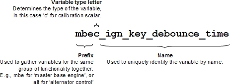
A three letter prefix code identifying which group of functionality the named item belongs to.
A single letter identifying the type of the named item (not used for displayable signals). See Table 5.1, “Variable naming convention” for a list of types.
The item type letter is as follows:
Table 5.1. Variable naming convention
| Named item type | Type letter |
|---|---|
| Displayable signals | (no type letter) |
| Constant scalars | k |
| Calibration scalars | c |
| Calibration maps | m |
| Arrays | v |
| Local variables | l |
| Subsystems | (task rate code) |
Subsystem task rate codes are defined on a per-project basis.
The following conventions should be adhered to when designing variable names:
A suffix is used on names of parameters of blocks such as lookup tables, where the parameters have the same name as the block with a defined suffix appended.
Names are case sensitive, but no reliance shall be placed on this. All names should be lower case except where otherwise stated below.
The sense of any boolean variables should be clear from the name of the variable.
All names must be valid C language identifiers.
Where there are multiple words in the descriptive body of a data name, the underscore character '_ should be used to separate the words.
Subsystems and Stateflow machines all have unique names. The name begins with the library prefix followed by a one letter code to define the task rate associated with that subsystem, and an underscore.
Where there are multiple words in the descriptive body of a subsystem or Stateflow machine name, each word should begin with a capital letter.
Axes and data for lookup tables should be given the name of the table, followed by a suffix. 1-d lookup tables have two parameters as follows:
Table 5.2. 1-d map lookup naming convention
Simulink parameter Suffix Example Vector of input values _x vaim_fuel_cell_temp_xVector of output values _z vaim_fuel_cell_temp_z2-d lookup tables have three parameters as follows:
Table 5.3. 2-d map lookup naming convention
Simulink parameter Suffix Example Row _x sffm_base_fuel_xColumn _y sffm_base_fuel_yTable _z sffm_base_fuel_zGiven that it is unlikely the data will be manually edited in MATLAB, the drawing convention above is adopted.
If a constant is literal (not a calibration item), its name will be in upper case and need not have the prefix. It is recommended, however, that the library prefix is retained (in upper case) for literals which relate only to one feature.
All calibration items and literals should be defined and have values assigned in the MATLAB base workspace.
Simulink ports are named as variables. Except for generic library blocks, the naming of ports should be consistent throughout the entire model hierarchy, such that differently named ports are never connected directly together.
Where a set of combinatorial logic is required to control events, it is generally neater and clearer to build up the logic using the Simulink Logical Operator blocks than to attempt to use Stateflow. Greater simplicity brings advantages in ease (and correctness and cost) of implementation and reviewing.
For example, suppose we need to know the result of:
((A and B) or (C and D))
We could model this in Stateflow using the following node diagram:
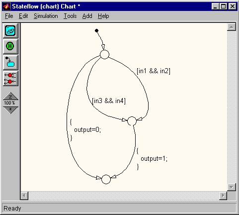
Alternatively we could use Simulink blocks as follows:
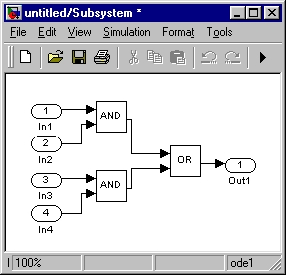
In addition, the C-code generated by the Simulink blocks is clean and efficient compared to the Stateflow version, though this is becoming less true with newer releases of Stateflow Coder and RTW. See also the section on Boolean signals below.
Stateflow is useful when modelling state-based strategies. These can be very well represented using the state chart notation, including the option of nested state machines. However, mixing the flow chart nodes into transitions between states produces a messy and confusing diagram. This is particularly true when actions are placed on transitions.
For this reason, state machines with flow nodes are to be avoided. A flow node may appear as the entry point from an initial transition for the purpose of selecting one of a small number of states when a chart (or particularly a sub-chart) is activated:
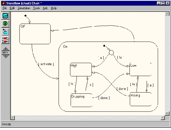
An analogous situation exists where a state has several exit conditions which share a common part. If (and only if) the non-common parts are mutually exhaustive, the transitions may be grouped through a flow node. The common part will be used as the condition to exit the state to the node, then the remaining conditions will form the exits from the node.
In all cases where a flow node appears on a chart it will have a complete exhaustive set of exit conditions. Thus the node is guaranteed to be transient, and will never cause Stateflow to 'back up'.
Actions should be specified using the entry, during and exit attributes of states. If an action is specified on a transition to a flow node, the behaviour is not intuitive, so these must be avoided. Transition actions are allowed when it is not possible to achieve the desired result using entry and exit only, but they should only appear on transitions directly from one state to another.
To avoid confusion as to which transition out of a state takes priority, the conditions on the transitions should be mutually exclusive.
Defensive programming practice requires that an action be defined for the case of a state machine in an illegal or undefined state. The default action would be to re-initialise the state machine via the initial transition. If this action is not appropriate then the diagram should be annotated appropriately. This applies only to hand-coded projects, since it is not possible to control Stateflow's handling of this condition.
In MATLAB R11 and later, the real time workshop is capable of handling a variety of data types, rather than just floating point. Conversions between data types can be achieved using the Data Type Conversion block, while all arithmetic blocks require that all their inputs and output are of the same type.
The use of type conversions is often required to interface between floating point strategy models and sensor or actuator hardware on the target platform.
In practice, however, the data type handling is rather limited. Only floating point and integer types are available, and there is no provision for fixed point values (or integers with scaling factors) (except by use of the fixed-point blockset, but values from that cannot be used in scaled form in Stateflow). Consequently it is not practical to use Simulink for automatically generating code for a fixed point processor target, since it would be necessary to explicitly model every scaling factor compensation. For example, take the following piece of maths:
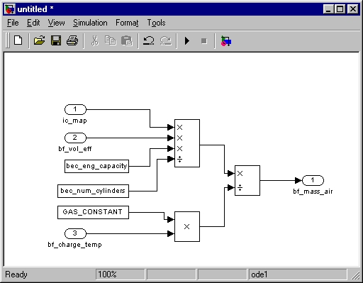
If we were to implement this using integer arithmetic, we would not only have raw values displayed in any scope blocks but we would also need to add scaling corrections and integer size conversions to result in the following:
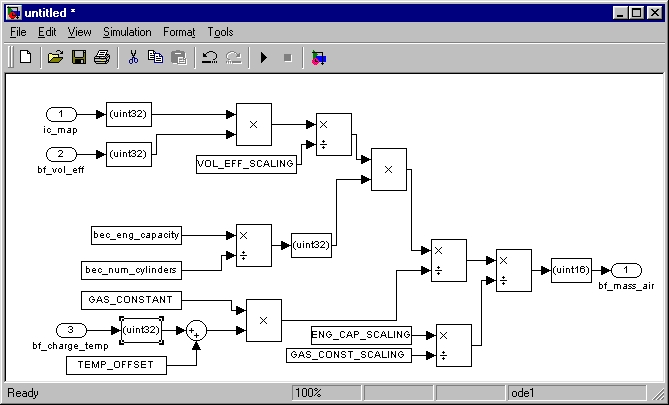
The use of Simulinks Boolean logic signals option is recommended. This causes RTW to use an integer-based Boolean type wherever a Boolean signal is implicitly generated, e.g. as the output from a logical operator block such as AND. This reduces RAM and CPU usage, and causes more efficient code to be generated for switch blocks, replacing the usual comparison against a threshold with a simple and fast if (boolean)... construct. (An error is issued if this would be inconsistent with the switch threshold value set.)
Similarly, it may be appropriate to use integer types for some signals, e.g. when passing an enumerated state variable. This saves RAM, reduces CPU use, and may remove the need to make exact floating-point comparisons later. But see the section on Logical operators, above; it is awkward to attempt to represent quantities which are naturally continuous (e.g. a pressure) as scaled integers.
Note
There is no problem passing a Boolean or integer signal into Stateflow, so long as Strong data typing is switched on in the Stateflow chart properties (otherwise, it expects only floating-point inputs and outputs).
The use of floating point arithmetic introduces certain potential issues. These are not specific to Simulink but are general problems with floating point.
Avoid direct equality tests. Floating point results will be rounded, and tests for exact equality are inherently risky.
- 6.1. OpenECU blockset reference
- 6.1.1. 1-d calibration map look-up and interpolation (put_Calmap1d)
- 6.1.2. 2-d calibration map look-up and interpolation (put_Calmap2d)
- 6.1.3. Application build date (psc_AppBuildDate)
- 6.1.4. Application version (psc_AppVersion)
- 6.1.5. Analogue input — basic (pai_BasicAnalogInput)
- 6.1.6. Analogue input — processed (pai_AnalogInput)
- 6.1.7. Analogue output (pax_AnalogOuput)
- 6.1.8. Build model (prtw_Build)
- 6.1.9. Boot code build date (psc_BootBuildDate)
- 6.1.10. Boot code version (psc_BootVersion)
- 6.1.11. Boot code part number (psc_BootPartNumber)
- 6.1.12. CAN bus status (pcx_BusStatus)
- 6.1.13. CAN configuration (pcx_CANConfiguration)
- 6.1.14. CAN receive message (pcx_CANReceiveMessage)
- 6.1.15. CAN transmit message (pcx_CANTransmitMessage)
- 6.1.16. CANdb message receive (pcx_CANdb_ReceiveMessage)
- 6.1.17. CANdb transmit message (pcx_CANdb_TransmitMessage)
- 6.1.18. CAN status — deprecated (pcx_CANStatus)
- 6.1.19. CCP configuration (pcp_CCPConfiguration)
- 6.1.20. CCP raster configuration (pcp_RasterConfig)
- 6.1.21. CCP seed/key security (pcp_CCPSecurity)
- 6.1.22. CCP inhibit reprogramming (pcp_CCPInhibitReprogramming)
- 6.1.23. CCP CRO receive count (pcp_CCPRxCount)
- 6.1.24. Compiler options (pcomp_CompileOptions)
- 6.1.25. Configure auto-coder (RTW EC) (prtw_ConfigUsingRtwEc)
- 6.1.26. Configure auto-coder (RTW RTMODEL) (prtw_ConfigUsingRtwRtmodel)
- 6.1.27. Configuration M250 (pcfg_Config_M250)
- 6.1.28. Configuration M460 (pcfg_Config_M460)
- 6.1.29. Configuration M670 (pcfg_Config_M670)
- 6.1.30. Constant current output (pax_CcOutput)
- 6.1.31. Constant current output — configuration for TLE8242-2 outputs (pax_CcConfigTle8242)
- 6.1.32. Constant current output — autozero for TLE8242-2 channels (pax_CcAutozeroTle8242)
- 6.1.33. Constant current output — monitor for TLE8242-2 channels (pax_CcReadCurrentTle8242)
- 6.1.34. Debounce (put_Debounce)
- 6.1.35. DTC clear all (pdtc_ClearAll)
- 6.1.36. DTC clear all if active (pdtc_ClearAllIfActive)
- 6.1.37. DTC clear all if inactive (pdtc_ClearAllIfInactive)
- 6.1.38. DTC diagnostic trouble code (pdtc_DiagnosticTroubleCode)
- 6.1.39. DTC enable periodic lamp updates (pdtc_EnablePeriodicLampUpdates)
- 6.1.40. DTC memory update (pdtc_Memory)
- 6.1.41. DTC table definition (pdtc_Table)
- 6.1.42. Digital input (pdx_DigitalInput)
- 6.1.43. Digital output (pdx_DigitalOutput)
- 6.1.44. Digital output monitor (pdx_Monitor)
- 6.1.45. Digital data input (pdd_DataInput)
- 6.1.46. Fault check (put_FaultCheck)
- 6.1.47. Frequency input (pdx_FrequencyInput)
- 6.1.48. Hall decode input measurement (pdx_HallDecodeInput)
- 6.1.49. H-Bridge output (pdx_HBridgeOutput)
- 6.1.50. J1939 configuration (pj1939_Configuration)
- 6.1.51. J1939 channel configuration (pj1939_ChannelConfiguration)
- 6.1.52. J1939 DM1 receive (pj1939_Dm1Receive)
- 6.1.53. J1939 DM1 decode DTC (pj1939_Dm1DecodeDtc)
- 6.1.54. J1939 DM1 transmit (pj1939_Dm1Transmit)
- 6.1.55. J1939 DM2 receive (pj1939_Dm2Receive)
- 6.1.56. J1939 DM2 decode DTC (pj1939_Dm2DecodeDtc)
- 6.1.57. J1939 DM2 transmit (pj1939_Dm2Transmit)
- 6.1.58. J1939 parameter group receive message (pj1939_PgReceive)
- 6.1.59. J1939 parameter group requested (pj1939_PgRequested)
- 6.1.60. J1939 parameter group transmit (pj1939_PgTransmit)
- 6.1.61. Link options (pcomp_LinkOptions)
- 6.1.62. Memory configuration (pmem_MemoryConfiguration)
- 6.1.63. Model identification (put_Identification)
- 6.1.64. Non-volatile adaptive check-sum (pnv_AdaptiveChecksum)
- 6.1.65. Non-volatile adaptive 1-d map look-up (pnv_AdaptiveMap1d)
- 6.1.66. Non-volatile adaptive 2-d map look-up (pnv_AdaptiveMap2d)
- 6.1.67. Non-volatile adaptive scalar (pnv_AdaptiveScalar)
- 6.1.68. Non-volatile adaptive array (pnv_Array)
- 6.1.69. Non-volatile memory status (pnv_Status)
- 6.1.70. Output control (pss_OutputControl)
- 6.1.71. Over-current trip reset (pss_OvercurTripReset)
- 6.1.72. Over current trip reset and diagnostic enable (pss_OvercurTripReset_DiagnEnable)
- 6.1.73. Peak and hold injector output (pdx_PeakHoldInjectorOutput)
- 6.1.74. Internal RAM test error (psc_InternalRamTestError)
- 6.1.75. Internal RAM test progress (psc_InternalRamTestProgress)
- 6.1.76. Internal ROM test error (psc_InternalRomTestError)
- 6.1.77. Internal ROM test progress (psc_InternalRomTestProgress)
- 6.1.78. Platform code build date (psc_PlatformBuildDate)
- 6.1.79. Platform code version (psc_PlatformVersion)
- 6.1.80. Platform code part number (psc_PlatformPartNumber)
- 6.1.81. Processor loading (psc_CpuLoading)
- 6.1.82. eTPU loading (psc_EtpuLoading)
- 6.1.83. PWM input measurement (pdx_PwmInput)
- 6.1.84. PWM output — fixed frequency (pdx_PWMOutput)
- 6.1.85. PWM output — variable frequency (pdx_PWMVariableFrequencyOutput)
- 6.1.86. PWM output — with synchronous sampling (pdx_PWMOutputWithSyncSampling)
- 6.1.87. Quadrature decode input (pdx_QuadratureDecode)
- 6.1.88. Quadrature decode and frequency input measurement (pdx_QuadratureDecodeAndFrequencyInput)
- 6.1.89. Range check (put_RangeCheck)
- 6.1.90. Reset module (put_Reset)
- 6.1.91. Reset count — stable (psc_ResetCount)
- 6.1.92. Reset count — unstable (psc_UnstableResetCount)
- 6.1.93. Reprogramming code build date (psc_PrgBuildDate)
- 6.1.94. Reprogramming code version (psc_PrgVersion)
- 6.1.95. Reprogramming code part number (psc_PrgPartNumber)
- 6.1.96. Retrieve registry key (preg_RetrieveKey)
- 6.1.97. Require platform version (put_RequirePlatformVersion)
- 6.1.98. Show Simulink's sample time colours (prtw_ShowSampleTimeColours)
- 6.1.99. SENT input (pdx_SentInput)
- 6.1.100. SENT input — serial data (pdx_SentSerialInput)
- 6.1.101. Signal gap detection (put_SignalGapDetection)
- 6.1.102. Signal prepare (put_SignalPrepare)
- 6.1.103. Signal validate (put_SignalValidate)
- 6.1.104. Slew rate check (put_SlewRateCheck)
- 6.1.105. SPI communication fault count (psp_FaultCount)
- 6.1.106. Stack used (psc_StackUsed)
- 6.1.107. PWM output — variable frequency, synchronised (pdx_PWMSynchronisedOutput)
- 6.1.108. Task duration (pkn_TaskDuration)
- 6.1.109. Task period overrun (pkn_TaskPeriodOverrun)
- 6.1.110. TargetLink Integration (ptl_TargetLinkSubsystem)
- 6.1.111. Time (real) (ptm_RealTime)
- 6.1.112. Time (Simulink) (ptm_SimulinkTime)
- 6.1.113. UEGO sensor control — CJ125 device (pcj125_Control)
- 6.1.114. Watchdog kick (psc_KickWatchdog)
- 6.1.115. Waveform — configuration, boost voltage (prop_BoostConfig)
- 6.1.116. Waveform — configuration, phases (prop_WaveformConfig)
- 6.1.117. Waveform — set channel (prop_WaveformSetChannel)
- 6.2. Automatic ASAP2 entries
- 6.2.1. Boot build information
- 6.2.2. Reprogramming build information
- 6.2.3. Platform build information
- 6.2.4. Application build information
- 6.2.5. Application and library task timing information
- 6.2.6. Memory use information
- 6.2.7. Memory error correction events
- 6.2.8. Floating point conditions
- 6.2.9. J1939 related information
- 6.3. OpenECU software versioning
- 6.4. OpenECU commands
The following sub-sections describe the layout and working of each OpenECU block. Each sub-section follows the same form, including diagrams of the block and its mask, a description of its functionality and a description of the block's inports, outports and any parameters.
Some inports, outports and parameters have a valid numerical range or size of vector. If so, the range and size information is given beside the object's description using internal notation.
Table 6.1. Interval notation
| Notation | Range |
|---|---|
| (x, y) | x < value < y |
| [x, y) | x <= value < y |
| (x, y] | x < value <= y |
| [x, y] | x <= value <= y |
Some objects are not clipped to a range but folded into a range using modulo arithmetic and where this occurs, the description includes details.
1-d map look-up and interpolation.
None (Main library). (See Section 1.3, “Licensed Features”.)
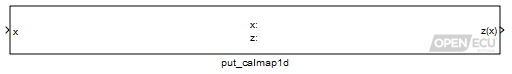
Looks up the inport x in the X-axis Data parameter, interpolates the corresponding elements in the Z Data parameter, giving a corresponding z(x) as the output.
Some calibration tools provide a feature which shows the map in graphical or tabular
form together with the active interpolation point. OpenECU supports this feature by populating
the ASAP2 file with the signal name which corresponds to the x inport.
To make this feature work, the x signal must be a named DD entity with its
storage class property set to ExportedGlobal.
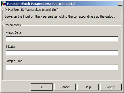
The name of the map's x axis (e.g.
vftm_mymap_x, see Section "Naming rules"). There must be two or more elements in this parameter and that must be the same as the number of elements in parameter Z data. The values of X-axis Data must increase monotonically but adjacent values may be the same.Value type: Real Calibratable: Yes, offline and online The name of the map's z axis (e.g.
vftm_mymap_z, see Section "Naming rules"). There must be two or more elements in this parameter and that must be the same as the number of elements in X-axis Data.Value type: Real Calibratable: Yes, offline and online The periodicity of the block execution.
Range: [0.001, 3600] seconds
Value type: Real Calibratable: No
The Simulink look-up and pre-index blocks can be used instead of the put_Calmap1d block. If a model uses the OpenECU data dictionary, then the axes and look-up data dictionary items must adhere to the naming convention and cannot be shared between look-up blocks. If a model uses the Simulink data dictionary, then the naming convention is not required, and axes and look-up DDEs can be reused between look-up blocks.
– Note that other combinations are possible, see Section 4.2.2.2, “Data dictionary files” for details.
– Note that in some cases, the Simulink look-up block can be slower to run than the put_Calmap1d block.
– Note that when using Simulink look-up blocks with the Diab compiler, the following warning message is emitted during model builds. The warning can be ignored.
'[model].c', line [line]: warning (dcc:1792):
                          trying to assign 'ptr to volatile' to 'ptr'
The look-up and interpolation work as follows:
If the inport x value is less than the first element or larger than the last element of parameter X-axis Data, the block outputs the first element or last element of parameter Z Data respectively as outport z(x).
Warning
This effectively clips the output value as if it were looked up at the nearest defined break-point, which differs from the behaviour of the standard Simulink look-up block in older versions (e.g., Simulink R12).
Otherwise, if the inport x is equal to the value of one of the elements of parameter X-axis Data, the block outputs the corresponding element of parameter Z Data as outport z(x).
Otherwise, if the inport x is equal to the value of more than one element of parameter X-axis Data and the corresponding elements in parameter Z Data differ (causing a discontinuity in the function), the earliest element in the parameter Z Data is output.
Otherwise, if the inport x is intermediate in value between two consecutive elements of parameter Z data, the block interpolates linearly between the two corresponding elements in parameter Z data using the scale defined by parameter X-axis Data to obtain outport z(x) value.
2-d map look-up and interpolation.
None (Main library). (See Section 1.3, “Licensed Features”.)
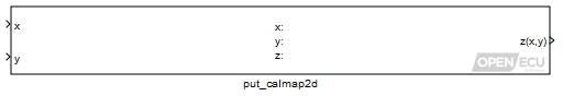
Looks up the input x and y in the X-axis Data and Y-axis Data parameters then interpolates between the corresponding Z Data parameter elements, giving a corresponding z(x,y) as output.
Some calibration tools provide a feature which shows the map in graphical or tabular
form together with the active interpolation point. OpenECU supports this feature by populating
the ASAP2 file with the signal names which correspond to the x and y inports.
To make this feature work, the x and y signals must be named DD entities with their
properties set to ExportedGlobal.
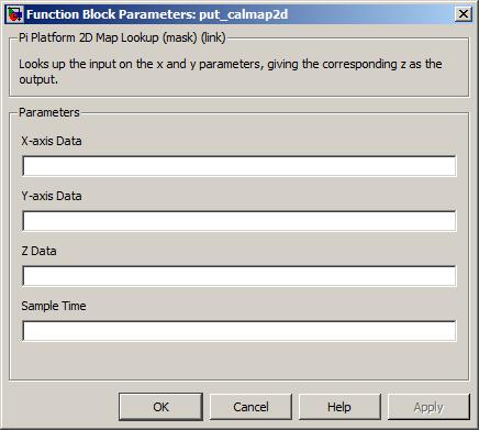
The name of the map's x axis (e.g.
vftm_mymap_x, see Section "Naming rules"). There must be two or more elements in this parameter and that must be the same as the number of elements as columns in parameter Z Data. The values of X-axis Data must increase monotonically but adjacent values may be the same.Value type: Real Calibratable: Yes, offline and online The name of the map's y axis (e.g.
vftm_mymap_y, see Section "Naming rules"). There must be two or more elements in this parameter and that must be the same as the number of elements as rows in parameter Z Data. The values of Y-axis Data must increase monotonically but adjacent values may be the same.Value type: Real Calibratable: Yes, offline and online The name of the map's z matrix (e.g.
vftm_mymap_z, see Section "Naming rules"). There must be the same number of rows as elements in parameter Y-axis Data and number of columns as elements in parameter X-axis Data.Value type: Real Calibratable: Yes, offline and online The periodicity of the block execution.
Range: [0.001, 3600] seconds
Value type: Real Calibratable: No
The Simulink look-up and pre-index blocks can be used instead of the put_Calmap2d block. If a model uses the OpenECU data dictionary, then the axes and look-up data dictionary items must adhere to the naming convention and cannot be shared between look-up blocks. If a model uses the Simulink data dictionary, then the naming convention is not required, and axes and look-up DDEs can be reused between look-up blocks.
– Note that other combinations are possible, see Section 4.2.2.2, “Data dictionary files” for details.
– Note that in some cases, the Simulink look-up block can be slower to run than the put_Calmap2d block.
– Note that when using Simulink look-up blocks with the Diab compiler, the following warning message is emitted during model builds. The warning can be ignored.
'[model].c', line [line]: warning (dcc:1792):
                          trying to assign 'ptr to volatile' to 'ptr'
The look-up and interpolation work as follows:
If the value of inport x lies outside the range defined by the smallest and largest values of parameter X-axis Data, it is altered until it meets that range (i.e. it is made equal to the nearest x value which does occur in parameter X-axis Data). Similarly the value of inport y is made to meet the range defined by the smallest and largest values in parameter Y-axis Data.
Warning
This effectively clips the output value as if it were looked up at the nearest defined break-point, which differs from the behaviour of the standard Simulink look-up block in older versions (e.g., Simulink R12).
If the point (x, y) is coincident with one of the intersections of the X-axis Data and Y-axis Data breakpoints (i.e. the value of inport x equals one of the values in parameter X-axis Data and the value of inport y equals one of the values in parameter Y-axis Data), the block outputs the corresponding element value of parameter Z Data with no interpolation. This includes the outer boundary (and corners) of the area defined by the x and y axes. If more than one point in either axis parameter equals the value of one of the inports, such that a discontinuity is defined in the surface, the lowest-indexed parameter element is selected.
If the point (x, y) is coincident with a X-axis Data element but lies between Y-axis Data elements, then the value output is linearly interpolated between the bounding points in the y direction referenced to the x axis. If two or more values in parameter X-axis Data equal the value of inport x, the lowest-indexed entry is used.
If the point (x, y) is coincident with a Y-axis Data element but lies between X-axis Data elements, then the value output is linearly interpolated between the bounding points in the x direction referenced to the y axis. If two or more values in Y-axis Data equal to the value of inport y, the lowest-indexed entry is used.
If the point (x, y) is not coincident with any X-axis Data or Y-axis Data elements, the outport z(x,y) is obtained by bi-linearly interpolating between the bounding points in the x and y axes defined by the lower-indexed x and y elements.
Get the build date for the ECU's application.
None (Main library). (See Section 1.3, “Licensed Features”.)
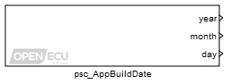
Gets the build date for the ECU's application. The build date can be used to distinguish between different versions of the application.
Only used under simulation and when the parameter Provide simulation inports is ticked. The outport year is set to the value of this inport for simulation purposes.
Range: [1970, 3000]
Only used under simulation and when the parameter Provide simulation inports is ticked. The outport month is set to the value of this inport for simulation purposes.
Range: [1, 12]
Only used under simulation and when the parameter Provide simulation inports is ticked. The outport day is set to the value of this inport for simulation purposes.
Range: [1, 31]
The year the application was built. Under simulation, if the Provide simulation inports parameter isn't ticked, the outport is set to the minimum of its range. The signal attached to the outport must be set as ExportedGlobal.
Range: [1970, 3000]
The month of the year the application was built. Under simulation, if the Provide simulation inports parameter isn't ticked, the outport is set to the minimum of its range. The signal attached to the outport must be set as ExportedGlobal.
Range: [1, 12]
The day of the month the application was built. Under simulation, if the Provide simulation inports parameter isn't ticked, the outport is set to the minimum of its range. The signal attached to the outport must be set as ExportedGlobal.
Range: [1, 31]
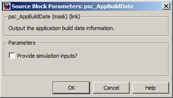
Get the version information for the ECU's application.
None (Main library). (See Section 1.3, “Licensed Features”.)
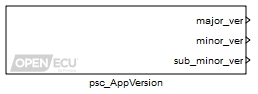
Gets the version information for the ECU's application. The version number is composed
of three fields, major, minor and sub-minor, typically written as major.minor.sub-minor.
The version can be used by the application for version control or diagnostics.
Only used under simulation and when the parameter Provide simulation inports is ticked. The outport major_ver is set to the value of this inport for simulation purposes.
Range: [0, 65535]
Only used under simulation and when the parameter Provide simulation inports is ticked. The outport minor_ver is set to the value of this inport for simulation purposes.
Range: [0, 65535]
Only used under simulation and when the parameter Provide simulation inports is ticked. The outport sub_minor_ver is set to the value of this inport for simulation purposes.
Range: [0, 65535]
The major version number of the application. Under simulation, if the Provide simulation inports parameter isn't ticked, the outport is set to the minimum of its range. The signal attached to the outport must be set as ExportedGlobal.
Range: [0, 65535]
The minor version number of the application. Under simulation, if the Provide simulation inports parameter isn't ticked, the outport is set to the minimum of its range. The signal attached to the outport must be set as ExportedGlobal.
Range: [0, 65535]
The sub-minor version number of the application. Under simulation, if the Provide simulation inports parameter isn't ticked, the outport is set to the minimum of its range. The signal attached to the outport must be set as ExportedGlobal.
Range: [0, 65535]

Tick to enable inports sim_major_ver, sim_minor_ver and sim_sub_minor_ver.
Read an analogue input channel and convert to a voltage.
None (Main library). (See Section 1.3, “Licensed Features”.)
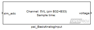
This block reads a physical analogue channel identified to obtain a raw input value when run on target hardware. When run in simulation, the block instead takes the value on its inport as its raw value.
A raw value is the number obtained from the analogue-to-digital converter in the ECU device scaled as if it had 10-bit resolution, such that 0 indicates the reference ground (0 V), -1023 indicates the lower reference voltage (-5V) and 1023 indicates the upper reference voltage (5V).
Note
The worst case conversion time for all analogue-to-digital values is ~500μs. Thus, when the software asks for an analogue-to-digital conversion, the analogue-to-digital value may be up to 500μs old.
Note
Once read, the [-5, 5]V range must be scaled by the application to the range indicated in the technical specification for the selected target.
Only used under simulation when the parameter Provide simulation input? is ticked. The outport voltage is written to the value of this inport scaled from A/D counts to a voltage.
Range: [-1023, 1023] A/D counts
Value type: Real
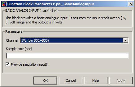
The channel pin for this analogue input.
Value type: List Calibratable: No The periodicity of the block execution.
Range: [0.001, 3600] seconds
Value type: Real Calibratable: No Tick to enable inport sim_adc.
Value type: Boolean Calibratable: No
Read an analogue input channel, convert to engineering units and fault check.
None (Main library). (See Section 1.3, “Licensed Features”.)
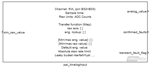
This block reads a physical analogue channel identified to obtain a raw input value when run on target hardware. When run in simulation, the block instead takes the value on its input as its raw value.
Depending on the block's configuration, a raw value is either a measure of the voltage on the processor's analog-input pin or the number obtained from the analogue-to-digital converter in the ECU device scaled as if it had 10-bit resolution, such that 0 indicates the reference ground (usually 0 volts) and 1023 indicates the upper reference voltage (usually 5 volts).
Note
The worst case conversion time for all analogue-to-digital values is ~500μs. Thus, when the software asks for an analogue-to-digital conversion, the analogue-to-digital value may be up to 500μs old.
When the Transfer function type is set to “Map”, the block converts the raw value into an engineering value through a 1-d table look-up. When set to “Linear”, the block uses a linear equation with a specified scale and offset to convert the raw value to engineering value.
An engineering value is the value which takes the physical units appropriate for a particular input device, e.g. kPa for a pressure sensor. This is obtained from the raw value through some appropriate transformation. As the user specifies the transformation in the mask, it is the responsibility of the user to choose appropriate and consistent units.
This block provides range and slew fault checking for analogue inputs. Range checking is performed for raw values as well as engineering values.
When any range or slew error is detected, the block initially yields the last good value held. If the leaky bucket confirms a fault however, the default value is output instead.
Filtering of faults is achieved using a leaky bucket algorithm. A leaky bucket integrator is used to decide when an input is confirmed as faulty as a function of its current state, which may be only transiently in error. Here the bucket always has a total volume or depth of unity (1.0). When the input is deemed to be in error (e.g. out of range), water is poured into the bucket at some rise rate. At all times water flows out of a leak in the bottom of the bucket with some fall rate until it is empty. If the bucket should ever fill to the brim by reaching a depth greater than or equal to 1.0, the input is confirmed as faulty. Should the bucket subsequently empty to below its hysteresis depth, it is no longer confirmed as faulty.
Engineering value of the analogue input conversion (see Transfer function for the conversion), possibly clamped to the default value if any faults are active.
Value type: Real Calibratable: No A vector of 5 outputs. if any are set, a confirmed fault condition is set.
Element Description Range 1 Raw output is below lower range limit. 0 or 1 2 Raw output is above upper range limit. 0 or 1 3 Slew rate fault for raw value. 0 or 1 4 Engineering output is below lower range limit. 0 or 1 5 Engineering output is above upper range limit. 0 or 1 Value type: Boolean Calibratable: No Whether the input value is currently faulty (e.g. out of range). A scalar flag.
Range: 0 or 1
Value type: Boolean Calibratable: No
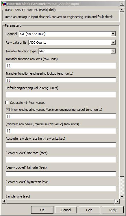
The channel pin for this analogue input.
Value type: List Calibratable: No The units in which the raw analogue input data is read. Either 'ADC Counts' (default) or 'Volts'.
Value type: List Calibratable: No The type of transfer function to use when converting from raw units to engineering units. Either 'Map' (default) or 'Linear'.
This enables or disables the following parameters:
Parameter Map Linear Transfer function raw axis Enabled Disabled Transfer function engineering look-up Enabled Disabled Transfer function scale Disabled Enabled Transfer function x offset Disabled Enabled Transfer function z offset Disabled Enabled Value type: List Calibratable: No Vector of breakpoints for z = f(x) raw value to engineering value look-up when Transfer function type is set to Map.
Range: [-1023, 1023] A/D counts, [-5, 5] Volts
Value type: Real Calibratable: Yes, offline and online Transfer function engineering look-up
Vector of data points for engineering value look-up when Transfer function type is set to Map.
Value type: Real Calibratable: Yes, offline and online Scale of transfer function when Transfer function type is set to Linear. 'm' for z = m*(x + a) + b
Value type: Real Calibratable: Yes, offline and online Offset of transfer function when Transfer function type is set to Linear. 'a' for z = m*(x + a) + b
Range: [-1023, 1023] A/D counts, [-5, 5] Volts
Value type: Real Calibratable: Yes, offline and online Offset of transfer function when Transfer function type is set to Linear. 'b' for z = m*(x + a) + b
Value type: Real Calibratable: Yes, offline and online Engineering value to be output if a fault condition is confirmed for this input.
Value type: Real Calibratable: Yes, offline and online Tick to separate min and max values into separate values, or combine into a vector.
This is accomplished by enabling or disabling the following parameters:
Parameter Unchecked Checked Minimum engineering value, Maximum engineering value Enabled Disabled Minimum raw value, Maximum raw value Enabled Disabled Minimum engineering value Disabled Enabled Maximum engineering value Disabled Enabled Minimum raw value Disabled Enabled Maximum raw value Disabled Enabled Value type: Boolean Calibratable: No Minimum engineering value, Maximum engineering value
Vector of minimum and maximum permissible engineering values before input considered faulty when Separate min/max values? is unchecked.
Value type: Real Calibratable: Yes, offline and online Minimum raw value, Maximum raw value
Vector of minimum and maximum permissible raw values before input considered faulty when Separate min/max values? is unchecked.
Range: [-1023, 1023] A/D counts, [-5, 5] Volts
Value type: Integer Calibratable: Yes, offline and online Minimum permissible engineering values before input considered faulty when Separate min/max values? is checked.
Value type: Real Calibratable: Yes, offline and online Maximum permissible engineering values before input considered faulty when Separate min/max values? is checked.
Value type: Real Calibratable: Yes, offline and online Minimum permissible raw values before input considered faulty when Separate min/max values? is checked.
Range: [-1023, 1023] A/D counts, [-5, 5] Volts
Value type: Integer Calibratable: Yes, offline and online Maximum permissible raw values before input considered faulty when Separate min/max values? is checked.
Range: [-1023, 1023] A/D counts, [-5, 5] Volts
Value type: Integer Calibratable: Yes, offline and online Maximum absolute rate of change of input calculated over one model iteration before input considered faulty.
Range: [-inf, inf] A/D counts/sec, [-inf, inf] Volts/sec,
Value type: Real Calibratable: Yes, offline and online Rate at which leaky bucket is filled when input is faulty in some respect.
Range: [0, 1000] /sec
Value type: Integer Calibratable: Yes, offline and online Rate at which leaky bucket is emptied if it is not already empty.
Range: [0, 1000] /sec
Value type: Integer Calibratable: Yes, offline and online Level below which bucket depth must fall before fault is no longer considered faulty. If set to a negative value, fault remains latched. As a special case, if the hysteresis depth is set negative, should the input ever reach a confirmed fault state it remains "latched" there until the ECU device is powered down.
Range: [-1, 1] unitless
Value type: Real Calibratable: Yes, offline and online The periodicity of the block execution.
Range: [0.001, 3600] seconds
Value type: Real Calibratable: No Tick to enable inport sim_raw_value.
Value type: Boolean Calibratable: No
Set an analogue output channel to a percentage of its range.
None (Main library). (See Section 1.3, “Licensed Features”.)
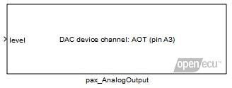
The analogue output block causes the channel pin to be driven to a requested voltage or resistance given by the level inport at every block iteration.
A value representing the percentage of the output voltage or resistance range to supply via the output channel. Note that the analogue output hardware implementation is target dependent. See the target technical specification for further details regarding the output transfer function.
Range: [0, 1] unitless
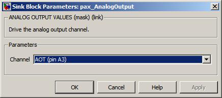
Start a model build.
None (Main library). (See Section 1.3, “Licensed Features”.)

A utility block to start a model build (equivalent to the keyboard shortcut CTRL-B when a Simulink model window is in focus).
Get the build date for the ECU's boot code.
None (Main library). (See Section 1.3, “Licensed Features”.)
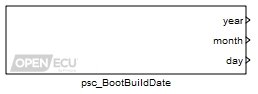
Gets the build date for the ECU's boot code. The build date can be used to distinguish between different versions of the boot code.
Only used under simulation and when the parameter Provide simulation inports is ticked. The outport year is set to the value of this inport for simulation purposes.
Range: [1970, 3000]
Only used under simulation and when the parameter Provide simulation inports is ticked. The outport month is set to the value of this inport for simulation purposes.
Range: [1, 12]
Only used under simulation and when the parameter Provide simulation inports is ticked. The outport day is set to the value of this inport for simulation purposes.
Range: [1, 31]
The year the boot code was built. Under simulation, if the Provide simulation inports parameter isn't ticked, the outport is set to the minimum of its range. The signal attached to the outport must be set as ExportedGlobal.
Range: [1970, 3000]
The month of the year the boot code was built. Under simulation, if the Provide simulation inports parameter isn't ticked, the outport is set to the minimum of its range. The signal attached to the outport must be set as ExportedGlobal.
Range: [1, 12]
The day of the month the boot code was built. Under simulation, if the Provide simulation inports parameter isn't ticked, the outport is set to the minimum of its range. The signal attached to the outport must be set as ExportedGlobal.
Range: [1, 31]
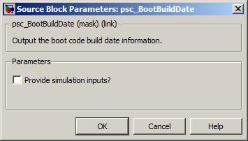
Get the version information for the ECU's boot code.
None (Main library). (See Section 1.3, “Licensed Features”.)
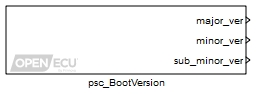
Gets the version information for the ECU's boot code. The version number is composed
of three fields, major, minor and sub-minor, typically written as major.minor.sub-minor.
The version can be used by the application for version control or diagnostics.
Only used under simulation and when the parameter Provide simulation inports is ticked. The outport major_ver is set to the value of this inport for simulation purposes.
Range: [0, 65535]
Only used under simulation and when the parameter Provide simulation inports is ticked. The outport minor_ver is set to the value of this inport for simulation purposes.
Range: [0, 65535]
Only used under simulation and when the parameter Provide simulation inports is ticked. The outport sub_minor_ver is set to the value of this inport for simulation purposes.
Range: [0, 65535]
The major version number of the boot code. Under simulation, if the Provide simulation inports parameter isn't ticked, the outport is set to the minimum of its range. The signal attached to the outport must be set as ExportedGlobal.
Range: [0, 65535]
The minor version number of the boot code. Under simulation, if the Provide simulation inports parameter isn't ticked, the outport is set to the minimum of its range. The signal attached to the outport must be set as ExportedGlobal.
Range: [0, 65535]
The sub-minor version number of the boot code. Under simulation, if the Provide simulation inports parameter isn't ticked, the outport is set to the minimum of its range. The signal attached to the outport must be set as ExportedGlobal.
Range: [0, 65535]
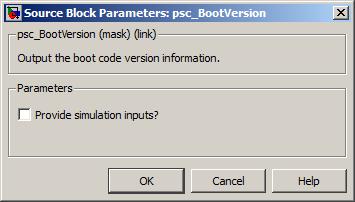
Tick to enable inports sim_major_ver, sim_minor_ver and sim_sub_minor_ver.
Get the part number information for the ECU's boot code.
None (Main library). (See Section 1.3, “Licensed Features”.)
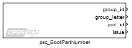
Gets the part number information for the ECU's boot code. The part number is composed
of four fields, group identification number, group identification letter, part identification number
and issue number, typically written as group_idgroup_letter-part_id Iss issue.
Example: 12T-168232 Iss 3
The part number can be used by the application for diagnostics, tracking and identification.
Only used under simulation and when the parameter Provide simulation inports is ticked. The outport group_id is set to the value of this inport for simulation purposes.
Range: [0, 255]
Only used under simulation and when the parameter Provide simulation inports is ticked. The outport group_letter is set to the value of this inport for simulation purposes.
Range: [0, 255]
Only used under simulation and when the parameter Provide simulation inports is ticked. The outport part_id is set to the value of this inport for simulation purposes.
Range: [0, 4294967295]
Only used under simulation and when the parameter Provide simulation inports is ticked. The outport issue is set to the value of this inport for simulation purposes.
Range: [0, 65535]
The Group Identification number of the part number of the boot code. Under simulation, if the Provide simulation inports parameter isn't ticked, the outport is set to the minimum of its range. The signal attached to the outport must be set as ExportedGlobal.
Range: [0, 255]
The Group Identification letter of the part number of the boot code. The value represents the ASCII code of the letter. Under simulation, if the Provide simulation inports parameter isn't ticked, the outport is set to the minimum of its range. The signal attached to the outport must be set as ExportedGlobal.
Range: [0, 255]
The Part Identification number of the part number of the boot code. Under simulation, if the Provide simulation inports parameter isn't ticked, the outport is set to the minimum of its range. The signal attached to the outport must be set as ExportedGlobal.
Range: [0, 4294967295]
The Issue number of the part number of the boot code. Under simulation, if the Provide simulation inports parameter isn't ticked, the outport is set to the minimum of its range. The signal attached to the outport must be set as ExportedGlobal.
Range: [0, 65535]
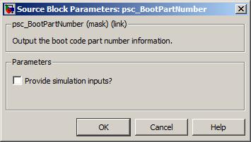
Tick to enable inports sim_group_id, sim_group_letter, sim_part_id and sim_issue.
Provide information about the error status of a CAN bus.
None (Main library). (See Section 1.3, “Licensed Features”.)
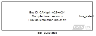
Provide the current error state of a CAN bus, one of error-active, error-passive or bus-off. See the Bosch CAN specification from their web site (http://www.can.bosch.com) or the ISO specification for more details.
In addition to the usual CAN bus-off error handling performed by the CAN controller, when a CAN bus-off condition is detected by the software, the software temporarily suspends CAN message transmission. A transmission is then attempted periodically in order to check whether the bus-off condition has been resolved. After the bus-off condition has been resolved, the software resumes message transmission as normal.
A dummy input for simulation purposes only. Set to zero to simulate an error-active state, set to 1 to simulate an error-passive state, and set to 2 to simulate a bus-off state. Only available if the mask parameter Provide simulation inputs is checked.
Value type: Integer Calibratable: No
Set to zero if the CAN bus selected through mask parameter CAN Bus Identifier is in the error-active state, set to 1 if in the error-passive state, and set to 2 if in the bus-off state.
Range: [0, 2]
Value type: Integer Calibratable: No
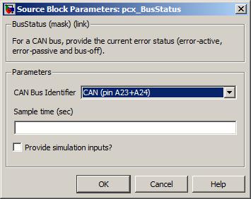
Which CAN bus to provide error state information about.
Value type: List Calibratable: No The periodicity of the block execution.
Range: [0.001, 3600] seconds
Value type: Real Calibratable: No If selected then simulation inport sim_bus_state is made available.
Value type: Boolean Calibratable: No
Specify the configuration for a CAN bus.
None (Main library). (See Section 1.3, “Licensed Features”.)
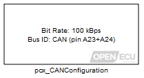
Specify the baud rate for a CAN bus. Some OpenECU devices support more than one CAN bus, in which case, more than one CAN configuration block is required to configure each.
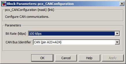
Some ECUs include CAN bus termination internal to the ECU, whilst some do not. Where CAN bus termination is not provided by the ECU, termination must be provided external to the ECU. Robust CAN communication requires correct termination. No termination or double termination can result in intermittent CAN messaging.
Receive a CAN message and unpack the message contents.
None (Main library). (See Section 1.3, “Licensed Features”.)
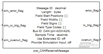
When a matching CAN message to this block is received, the block unpacks the message contents into individual signals, as specified by the block mask parameters, and provides them as outports. It is up to the application to provide an appropriate response (if one is required).
The block can provide a time stamp of when the message was received (see block mask parameter Provide Timestamp). The time stamp is a low accuracy time stamp, taken a short period of time after the message is received. That period of time is variable depending on the load of the processor and will therefore suffer jitter.
The pcx_CANdb_ReceiveMessage block provides a more convenient mechanism for specifying CAN information.
Warning
The PCX feature takes precedence over the PJ1939 feature. If you configure the PCX feature to receive a J1939 frame, the PJ1939 feature will not see the frame, and it will not be processed by the platform. This especially causes problems when receiving J1939 DM14 'Boot Load' commands.
A dummy input for simulation purposes only; may be grounded if not required. The value of outport error_flag in simulation.
Value type: Boolean Calibratable: No A dummy input for simulation purposes only; may be grounded if not required. The value of outport rx_trig_flag in simulation.
Value type: Boolean Calibratable: No A dummy input for simulation purposes only; may be grounded if not required. The value of outport overrun_flag in simulation.
Value type: Boolean Calibratable: No A dummy input for simulation purposes only; may be grounded if not required. The value of the output timestamp in simulation. Only available if the mask parameter Provide Timestamp is selected.
Value type: Integer
Set to 1 if some error has occurred which prevents CAN reception, or 0 otherwise.
Type Conditions setting outport error_flag to 1 run time the size of the most recently received message differs from the one used in configuration configuration message not configured, because too many receive messages Value type: Boolean Calibratable: No Set to 1 if this message has been received at this iteration, or 0 otherwise. This flag will be set even if the received message length differs from the expected length.
Value type: Boolean Calibratable: No Set to 1 if more than one message with the same CAN message identifier has been received in one model iteration, or 0 otherwise. If more than one message has been received, the data from the latest message is used.
Value type: Boolean Calibratable: No A low accuracy time stamp of when the message was last received as indicated by rx_trig_flag, or zero if the message has never been received. The time stamp is a free running microsecond timer, which wraps to zero at its maximum (rather than saturating). Only available if the mask parameter Provide Timestamp is selected.
Value type: Integer
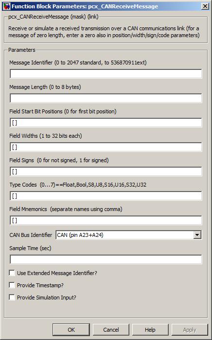
The unique can identifier of the message to be received.
Range: [0, 2047] if standard identifier
Range: [0, 536870911] if extended identifier
Value type: Integer Calibratable: No The number of data bytes to be received.
Range: [0, 8] bytes
Value type: Integer Calibratable: No A vector of bit numbers indicating the position at which each input Item begins in the CAN message. 0 corresponds to the least significant bit of data byte 0 of the message and 63 to the most significant byte of data byte 7 of the message, assuming these exist. For items whose bit length entry exceeds 7, the bit length must be one of: 0, 8, 16, 24, 32, 40, 48, 56.
Size: [1, 64] elements
Range: [0, 8], 16, 24, 32, 40, 48, 56 bit positions
Value type: Integer Calibratable: No A vector of bit lengths indicating the number of bits used to transmit each input Item. The following values are allowed: 1, 2, 3, 4, 5, 6, 7, 8, 9, 10, 11, 12, 13, 14, 15, 16, 24 and 32. Items of 8 bits or fewer may not be defined so as to straddle CAN byte boundaries.
Size: [1, 64] elements
Range: [1, 16], 24 or 32 bit width
Value type: Integer Calibratable: No A vector of 1 or 0 values. Corresponding data items for which this is set 1 are received as twos-complement signed numbers, or unsigned numbers otherwise.
Size: [1, 64] elements
Range: 0 or 1
Value type: Integer Calibratable: No This block provides one data field input for each element in Field Start Positions, as follows:
Table 6.2. CAN block type codes
Type code Simulink data type 0 real_T (single floating point type) 1 default boolean (boolean or real_T depending on current setting of Simulink Boolean logic signals setting) 2 signed 8 bit integer (int8_T) 3 unsigned 8 bit integer (uint8_T) 4 signed 16 bit integer (int16_T) 5 unsigned 16 bit integer (uint16_T) 6 signed 32 bit integer (int32_T) 7 unsigned 32 bit integer (uint32_T)
Value type: Integer Calibratable: No A string containing a comma-separated list of names with which to label the simulation input and CAN data output ports.
Value type: String Calibratable: No Which can bus the message will be received on.
Value type: Integer Calibratable: No The periodicity of the block execution.
Range: [0.001, 3600] seconds
Value type: Real Calibratable: No Use Extended Message Identifier?
If box is checked the 29 bit identifier is to be used, otherwise the 11 bit standard identifier is to be used.
Value type: Boolean Calibratable: No If selected then inport sim_timestamp and outport timestamp are made available.
Value type: Boolean Calibratable: No If selected then dummy inputs for each of the outport can message signals, such as
sim_signal_name, are provided by the block.Value type: Boolean Calibratable: No
Unused signals in a CAN message need not be specified in the Field Start Bit Positions parameter.
Not all OpenECU modules have both CAN buses populated (see Section A.1, “ECU hardware reference documentation” for details about each device).
The signal data outports are updated any time a message is received as indicated by rx_trig_flag. If the error_flag outport is asserted due to a mismatch in message size, the data outports will contain potentially erroneous data from the incorrectly sized message. It is recommended that the application software latch the values of all CAN signals only when rx_trig_flag is set and error_flag is not set.
If the block shows unnamed outports, it is likely that one or more of the block fields is incorrect. Check the fields for mistakes and correct them.
The restrictions involving alignment of data items with 8 or more bits can be overcome by combining the smaller data items from the CAN message into larger data items using some Simulink math blocks, or by using the pcx_CANdb_ReceiveMessage block.
All data is unpacked in Motorola byte ordering (MS byte first, LS byte last). The order of byte unpacking can be overcome by combining the smaller data items from the CAN message into larger data items using some Simulink math blocks, or by using the pcx_CANdb_ReceiveMessage block.
Providing fewer than 8 entries in the Field Mnemonics parameter will result in some ports not being named. Providing greater than 8 entries in the Field Mnemonics parameter will result in corruption in the mask displayed on the block. This is a display artifact only and in both cases the port signals will still function as normal.
Pack a CAN message with data then transmit it.
None (Main library). (See Section 1.3, “Licensed Features”.)
When a message is to be transmitted, the block packs each of the signal inports into the message, as specified by the block mask parameters, and transmits the message.
The pcx_CANdb_TransmitMessage block provides a more convenient mechanism for specifying CAN information.
A dummy input for simulation purposes only; may be grounded if not required. The value of outport error_flag in simulation.
Value type: Boolean Calibratable: No A dummy input for simulation purposes only; may be grounded if not required. The value of outport request_count in simulation. Only available if the mask parameter Provide Transmission Status is selected.
Value type: Integer A dummy input for simulation purposes only; may be grounded if not required. The value of outport overwrite_count in simulation. Only available if the mask parameter Provide Transmission Status is selected.
Value type: Integer A dummy input for simulation purposes only; may be grounded if not required. The value of outport ack_count in simulation. Only available if the mask parameter Provide Transmission Status is selected.
Value type: Integer
Set to 1 if some error has occurred which prevents CAN transmission, otherwise set to 0.
Type Conditions setting outport error_flag to 1 run time the message has been queued waiting for a transmit buffer to become available run time the bus is in bus off state configuration the bus has not been configured configuration message not configured, because too many transmit messages Value type: Boolean Calibratable: No A free running count of the application requests to transmit a message. The counter wraps to zero after reaching 65535. Only available if the mask parameter Provide Transmission Status is selected.
Value type: Integer A free running count of transmission requests which were queued by the software for later transmission because the CAN controller could not immediately accept the message for transmission. A queued message can be overwritten by subsequent attempts to transmit the same message (for instance, if the CAN bus is heavily loaded and the transmission rate high, the CAN controller may not be able to transmit the message before the application requests it is sent again, possibly with different data control from the previous request). The counter wraps to zero after reaching 65535. Only available if the mask parameter Provide Transmission Status is selected.
Value type: Integer A free running count of message transmissions successfully made by the CAN controller (i.e., those transmit messages which were acknowledged by at least one CAN node on the bus, not including the transmitting node). The counter wraps to zero after reaching 65535. Only available if the mask parameter Provide Transmission Status is selected.
Value type: Integer
The unique can identifier of the message to be transmitted.
Range: [0, 2047] if standard identifier
Range: [0, 536870911] if extended identifier
Value type: Integer Calibratable: No The number of data bytes to be transmitted.
Range: [0, 8] bytes
Value type: Integer Calibratable: No A vector of bit numbers indicating the position at which each input Item begins in the CAN message. 0 corresponds to the least significant bit of data byte 0 of the message and 63 to the most significant byte of data byte 7 of the message, assuming these exist. For items whose bit length entry exceeds 7, the bit length must be one of: 0, 8, 16, 24, 32, 40, 48, 56.
Size: [1, 64] elements
Range: [0, 8], 16, 24, 32, 40, 48, 56 bit positions
Value type: Integer Calibratable: No A vector of bit lengths indicating the number of bits used to transmit each input Item. The following values are allowed: 1, 2, 3, 4, 5, 6, 7, 8, 9, 10, 11, 12, 13, 14, 15, 16, 24 and 32. Items of 8 bits or fewer may not be defined so as to straddle CAN byte boundaries.
Size: [1, 64] elements
Range: [1, 16], 24 or 32 bit width
Value type: Integer Calibratable: No A vector of 1 or 0 values. Corresponding data items for which this is set 1 are transmitted as twos-complement signed numbers, or unsigned numbers otherwise.
Size: [1, 64] elements
Range: 0 or 1
Value type: Integer Calibratable: No This block provides one data field input for each element in Field Start Positions, as given in Table 6.2, “CAN block type codes”.
Value type: Integer Calibratable: No A string containing a comma-separated list of names with which to label the simulation input and CAN data output ports.
Value type: String Calibratable: No Which can bus the message will be transmitted on.
Value type: List Calibratable: No Use Extended Message Identifier?
If box is checked the 29 bit identifier is to be used, otherwise the 11 bit standard identifier is to be used.
Value type: Boolean Calibratable: No If selected then outports request_count, overwrite_count and ack_count, and their corresponding simulation inports, are made available.
Value type: Boolean Calibratable: No If selected then dummy outputs for each of the inport can message signals, such as
sim_signal_name, are provided by the block.Value type: Boolean Calibratable: No
Unused signals in a CAN message need not be specified in the Field Start Bit Positions parameter.
Not all OpenECU modules have both CAN buses populated (see Section A.1, “ECU hardware reference documentation” for details about each device).
If the block shows unnamed inports, it is likely that one or more of the block fields is incorrect. Check the fields for mistakes and correct them.
The restrictions involving alignment of data items with 8 or more bits can be overcome by combining the smaller data items from the CAN message into larger data items using some Simulink math blocks, or by using the pcx_CANdb_TransmitMessage block.
All data is packed in Motorola byte ordering (MS byte first, LS byte last). The order of byte packing can be overcome by combining the smaller data items from the CAN message into larger data items using some Simulink math blocks, or by using the pcx_CANdb_TransmitMessage block.
Providing fewer than 8 entries in the Field Mnemonics parameter will result in some ports not being named. Providing greater than 8 entries in the Field Mnemonics parameter will result in corruption in the mask displayed on the block. This is a display artifact only and in both cases the port signals will still function as normal.
Receive a CAN message, the identifier and contents of which are defined by a Vector CANdb file.
None (Main library). (See Section 1.3, “Licensed Features”.)
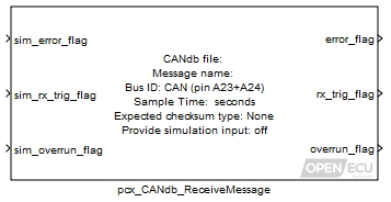
When a matching message to this block is received, the block unpacks the message contents into individual signals, as specified by the CANdb information, and provides them as outports in engineering units.
A CANdb file is a database of information regarding CAN nodes and CAN bus messages (more information regarding this format can be found by visiting the web site of Vector CANtech, Inc.). The database is edited using custom tools which make creation and maintenance of message information easier.
For each message, the database stores information like the message identifier, whether the identifier is standard or extended, what signals the message contains, etc.. For each signal, the database stores the start bit position, the bit length, bit ordering etc.. This block provides access to this information using the textual names assigned in the database, making the blocks easier to create and maintain (in contrast to the pcx_CANReceiveMessage block).
The block can provide a time stamp of when the message was received (see block mask parameter Provide Timestamp). The time stamp is a low accuracy time stamp, taken a short period of time after the message is received. That period of time is variable depending on the load of the processor and will therefore suffer jitter.
Warning
The PCX feature takes precedence over the PJ1939 feature. If you configure the PCX feature to receive a J1939 frame, the PJ1939 feature will not see the frame, and it will not be processed by the platform. This especially causes problems when receiving J1939 DM14 'Boot Load' commands.
A dummy input for simulation purposes only; may be grounded if not required. The value of outport error_flag in simulation.
Value type: Boolean Calibratable: No A dummy input for simulation purposes only; may be grounded if not required. The value of outport rx_trig_flag in simulation.
Value type: Boolean Calibratable: No A dummy input for simulation purposes only; may be grounded if not required. The value of outport overrun_flag in simulation.
Value type: Boolean Calibratable: No A dummy input for simulation purposes only; may be grounded if not required. The value of outport timestamp in simulation. Only available if the mask parameter Provide Timestamp is selected.
Value type: Integer A dummy input for simulation purposes only; may be grounded if not required. The value of outport checksum_err in simulation. Only available if the mask parameter Checksum Type is not None.
Value type: Boolean
Set to 1 if some error has occurred which prevents CAN reception, or 0 otherwise.
Type Conditions setting outport error_flag to 1 run time the size of the most recently received message differs from the one used in configuration configuration message not configured, because too many receive messages Value type: Boolean Calibratable: No Set to 1 if this message has been received at this iteration, or 0 otherwise. This flag will be set even if the received message length differs from the expected length.
Value type: Boolean Calibratable: No Set to 1 if more than one message with the same CAN message identifier has been received in one model iteration, or 0 otherwise. If more than one message has been received, the data from the latest message is used.
Value type: Boolean Calibratable: No A low accuracy time stamp of when the message was last received as indicated by rx_trig_flag, or zero if the message has never been received. The time stamp is a free running microsecond timer, which wraps to zero at its maximum (rather than saturating). Only available if the mask parameter Provide Timestamp is selected.
Value type: Integer Set TRUE if the most recently received message failed checksum validation or FALSE otherwise. Only available if the mask parameter Checksum Type is not None.
Value type: Boolean
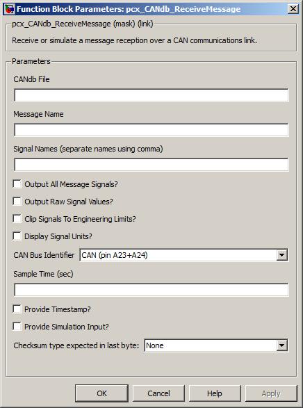
The name of the CANdb file, including extension. A path may be included, either relative or absolute, however the directory containing the file must be on the MATLAB search path. If more than one file has a matching (partial) path and filename, precedence is given firstly to the current MATLAB directory and then to the first location on the MATLAB search path.
Only textual CANdb files are accepted (see restrictions in the notes section below).
Value type: String Calibratable: No The name of the message to receive. The name must be specified in the CANdb file and must match case (e.g., message name
EngineRPMis different from message nameenginerpm).Value type: String Calibratable: No A comma separated list of signal names to unpack from the message (e.g., "name1,name2" without the quotes). An empty list of names to unpack is supported, in which case the block shows no additional outports. This mode can be used to detect the presence of a message on the CAN bus without decoding any of the CAN message contents.
Value type: String Calibratable: No If selected then all signals from the message are created as outports (similarly simulation inports if required), if unselected then only those signals in the signal names field are created as outports.
If this field is ticked and the dialog closed, next time this field is unticked, the signal names field will contain the complete list of signals. This mechanism is useful when filling in the dialog for the first time but you are unsure of the field names (e.g., open block, fill in CANdb file name, message name, CAN bus and sample time, then tick this field, close the dialog, then select the block again, untick this field, then edit the list of required signals).
Value type: Boolean Calibratable: No If selected, a second set of outports are created for the message signals, each set to the raw integer value extracted from the CAN message prior to being scaled into engineering units.
The raw values are always reported as unsigned integers. If the CANdb signal is signed, then the application is responsible for conversion into a signed value. 32-bit signals may be converted by casting. Signals less than 32-bits must be sign extended to 32-bits prior to casting.
Value type: Boolean Calibratable: No Clip Signals To Engineering Limits?
If selected, each outport (except for the raw signal outports) is clipped to the limits for that signal defined by the CANdb file.
Value type: Boolean Calibratable: No If selected then each of the can message outport signals (and simulation inport signals) show their engineering units, if the CANdb file defines those units.
Value type: Boolean Calibratable: No Which can bus the message will be received on.
Value type: Integer Calibratable: No The periodicity of the block execution.
Range: [0.001, 3600] seconds
Value type: Real Calibratable: No If selected then inport sim_timestamp and outport timestamp are made available.
Value type: Boolean Calibratable: No A drop-down selection of the type of checksum to expect in the last raw message byte, computed over all of the preceding raw bytes in the message (even if they are not used by any signals). The default is None, and the other currently supported option is the 8-bit CRC defined by SAE-J1850. If used, the outport checksum_err is filled accordingly. In simulation, the value from inport sim_checksum_err is passed through.
Value type: List Calibratable: No If selected then dummy inputs for each of the outport can message signals, such as
sim_signal_name, are provided by the block.Value type: Boolean Calibratable: No
Unused signals in a CAN message need not be specified in the Signal Names parameter.
Not all OpenECU modules have both CAN buses populated (see Section A.1, “ECU hardware reference documentation” for details about each device).
The signal data outports are updated any time a message is received as indicated by rx_trig_flag. If the error_flag outport is asserted due to a mismatch in message size, the data outports will contain potentially erroneous data from the incorrectly sized message. It is recommended that the application software latch the values of all CAN signals only when rx_trig_flag is set and error_flag is not set.
If the block does not show expected signals as outports, it is likely that one or more of the block fields is incorrect. Check the fields for mistakes and correct them.
Vector do not release the file format of CANdb files, so this block reads CANdb files as best it can. When reading the CANdb file, if it cannot understand the file format, the block will not show the request outports. Update the diagram to find out what the problem is.
If the block does not show the signal outports expected, there is probably a mistake in the CANdb file name or one of the signal names. Update the diagram to find out what the error is.
The CANdb blocks do not support extended signal multiplexing. If extended signal multiplexing is present in the CANdb file, then the block will not be able to interpret the file.
The CANdb blocks do not support signals defined in the CANdb file as signal type "double"
The CANdb blocks do not support CANdb messages without signals. For these messages, use the pcx_CANReceiveMessage block.
Due to the internal design of the CANdb blocks, a loss of precision may occur when dealing with integer values greater than 23 bits in size. This error increases as the value of the signal increases beyond this limit. If integer precision is required, it is recommended that the raw signal outports be used and for any scaling/offset specified in the DBC to be implemented by the application.
Transmit a CAN message, the identifier and contents of which are defined by a Vector CANdb file.
None (Main library). (See Section 1.3, “Licensed Features”.)
When a message is to be transmitted, the block encodes each of the signal inports into the message, as specified by the CANdb information, and transmits the message.
A CANdb file is a database of information regarding CAN nodes and CAN bus messages (more information regarding this format can be found by visiting the web site of Vector CANtech, Inc.). The database is edited using custom tools which make creation and maintenance of message information easier.
For each message, the database stores information like the message identifier, whether the identifier is standard or extended, what signals the message contains, etc.. For each signal, the database stores the start bit position, the bit length, bit ordering etc.. This block provides access to this information using the textual names assigned in the database, making the blocks easier to create and maintain (in contrast to the pcx_CANTransmitMessage block).
Warning
In some cases, the CAN database will contain messages with multiplexed signals (more than one signal is defined in a message with the same bit position and length). In order to use such a message, the user must pre-select only one of the signals to transmit. To do this, refer to Input All Message Signals?.
A dummy input for simulation purposes only; may be grounded if not required. The value of outport error_flag in simulation.
Value type: Boolean Calibratable: No A dummy input for simulation purposes only; may be grounded if not required. The value of outport request_count in simulation. Only available if the mask parameter Provide Transmission Status is selected.
Value type: Integer A dummy input for simulation purposes only; may be grounded if not required. The value of outport overwrite_count in simulation. Only available if the mask parameter Provide Transmission Status is selected.
Value type: Integer A dummy input for simulation purposes only; may be grounded if not required. The value of outport ack_count in simulation. Only available if the mask parameter Provide Transmission Status is selected.
Value type: Integer
Set to 1 if some error has occurred which prevents CAN transmission, otherwise set to 0.
Type Conditions setting outport error_flag to 1 run time the message has been queued waiting for a transmit buffer to become available run time the bus is in bus off state configuration the bus has not been configured configuration message not configured, because too many transmit messages Value type: Boolean Calibratable: No A free running count of the application requests to transmit a message. The counter wraps to zero after reaching 65535. Only available if the mask parameter Provide Transmission Status is selected.
Value type: Integer A free running count of transmission requests which were queued by the software for later transmission because the CAN controller could not immediately accept the message for transmission. A queued message can be overwritten by subsequent attempts to transmit the same message (for instance, if the CAN bus is heavily loaded and the transmission rate high, the CAN controller may not be able to transmit the message before the application requests it is sent again, possibly with different data control from the previous request). The counter wraps to zero after reaching 65535. Only available if the mask parameter Provide Transmission Status is selected.
Calibratable: No A free running count of message transmissions successfully made by the CAN controller (i.e., those transmit messages which were acknowledged by at least one CAN node on the bus, not including the transmitting node). The counter wraps to zero after reaching 65535. Only available if the mask parameter Provide Transmission Status is selected.
Value type: Integer
The name of the CANdb file, including extension. A path may be included, either relative or absolute, however the directory containing the file must be on the MATLAB search path. If more than one file has a matching (partial) path and filename, precedence is given firstly to the current MATLAB directory and then to the first location on the MATLAB search path.
Only textual CANdb files are accepted (see restrictions in the notes section below).
Value type: String Calibratable: No The name of the message to transmit. The name must be specified in the CANdb file and must match case (e.g., message name EngineRPM is different from message name enginerpm).
Value type: String Calibratable: No A comma separated list of signal names to pack into the message (e.g., "name1,name2" without the quotes). An empty list of names is supported, in which case the block shows no additional outports.
Value type: String Calibratable: No If selected then all signals from the message are created as inports (similarly simulation outports if required), if unselected then only those signals in the signal names field are created as inports.
If this field is ticked and the dialog closed, next time this field is unticked, the signal names field will contain the complete list of signals. This mechanism is useful when filling in the dialog for the first time but you are unsure of the field names (e.g., open block, fill in CANdb file name, message name and CAN bus, then tick this field, close the dialog, then select the block again, untick this field, then edit the list of required signals).
Value type: Boolean Calibratable: No Clip Signals To Engineering Limits?
If selected then each signal shall be clipped to their engineering limits.
Value type: Boolean Calibratable: No If selected then each of the can message inport signals (and simulation outport signals) show their engineering units, if the CANdb file defines those units.
Value type: Boolean Calibratable: No Which can bus the message will be transmitted on.
Value type: List Calibratable: No If selected then outports request_count, overwrite_count and ack_count, and their corresponding simulation inports, are made available.
Value type: Boolean Calibratable: No A drop-down selection of the type of checksum to apply to the last raw byte in the message, computed over all of the preceding raw bytes in the message (even if they are not used by any signals). The default is None, and the other currently supported option is the 8-bit CRC defined by SAE-J1850.
Value type: List Calibratable: No If selected then dummy outports for each of the outport can message signals are provided by the block.
Value type: Boolean Calibratable: No
Unused signals in a CAN message need not be specified in the Signal Names parameter.
Not all OpenECU modules have both CAN buses populated (see Section A.1, “ECU hardware reference documentation” for details about each device).
If the block does not show expected signals as inports, it is likely that one or more of the block fields is incorrect. Check the fields for mistakes and correct them.
Vector do not release the file format of CANdb files, so this block reads CANdb files as best it can. When reading the CANdb file, if it cannot understand the file format, the block will not show the request inports. Update the diagram to find out what the problem is.
If the block does not show the signal inports expected, there is probably a mistake in the CANdb file name or one of the signal names. Update the diagram to find out what the error is.
The CANdb blocks do not support extended signal multiplexing. If extended signal multiplexing is present in the CANdb file, then the block will not be able to interpret the file.
The CANdb blocks do not support signals defined in the CANdb file as signal type "double"
The CANdb blocks do not support CANdb messages without signals. For these messages, use the pcx_CANTransmitMessage block.
Due to the internal design of the CANdb blocks, a loss of precision may occur when dealing with integer values greater than 23 bits in size. This error increases as the value of the signal increases beyond this limit. If integer precision is required, it is recommended that the pcx_CANTransmitMessage block be used and for any scaling/offset specified in the DBC to be implemented by the application.
Provide information about CAN bus off status.
None (Main library). (See Section 1.3, “Licensed Features”.)
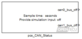
Provide the bus off state of each CAN bus as an outport. A CAN bus goes bus off when sufficient errors have been detected by the CAN transceiver. See the Bosch CAN specification from their web site (http://www.can.bosch.com) or the ISO specification for more details.
When CAN bus off condition is detected, CAN transmission activity is suspended. A transmission is then tempted periodically in order to check whether bus off condition has been resolved. After bus off condition is resolved, transmission resumes as normal.
Only used during simulation. Set to 1 to simulate a CAN bus off state for CAN bus 0, zero otherwise. Only available if the mask parameter Provide simulation input is checked.
Value type: Boolean Calibratable: No Only used during simulation. Set to 1 to simulate a CAN bus off state for CAN bus 1, zero otherwise. Only available if the mask parameter Provide simulation input is checked.
Value type: Boolean Calibratable: No
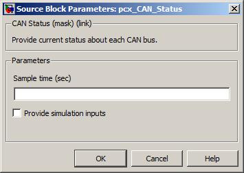
Not all OpenECU modules have both CAN buses populated (see Section A.1, “ECU hardware reference documentation” for details about each device).
This block became deprecated in version 1.8.4 and will be removed in a future version of the software. Please change to use the Section 6.1.12, “CAN bus status (pcx_BusStatus)” block.
This block configures the way OpenECU handles any CAN Calibration Protocol (CCP) messages it receives.
None (Main library). (See Section 1.3, “Licensed Features”.)
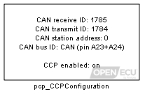
The CAN Calibration Protocol (CCP) is a CAN based messaging system designed to allow tools to access information in real-time. For more details, refer to ASAM Standards: ASAM MCD: MCD 1a at the ASAM Web site (http://www.asam.de).
This block configures OpenECU's CCP settings. The user can choose the transmit and receive CAN message identifiers, the CCP station address and the CAN bus communications will take place over. The block also configures whether CCP communications can take place when the ECU is in application mode running the model.
If the block is absent from the model, CCP communications is disabled when the model is running. CCP communications are still possible when OpenECU is being reprogrammed.
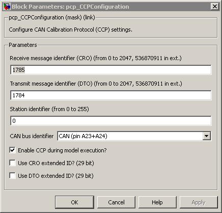
A unique CAN message identifier for CCP CRO messages.
Range: [0, 2047] or [0, 536870911] when Use CRO extended ID? (29 bit) is selected.
Value type: Integer Calibratable: No A unique CAN message identifier for CCP DTO messages.
Range: [0, 2047] or [0, 536870911] when Use DTO extended ID? (29 bit) is selected.
Value type: Integer Calibratable: No The station address for CCP sessions. OpenECU will only communicate using CCP if a session is opened using this station address. This feature is often used for connecting multiple CCP devices to the same CAN bus using the same CRO and DTO identifiers.
Range: [0, 255]
Value type: Integer Calibratable: No Which can bus CCP communications will occur on.
Value type: List Calibratable: No Enable CCP during model execution?
If checked, then CCP communications is enabled while the model is running. If unchecked, CCP communications is disabled while the model is running. In either case, CCP communications is enabled when reprogramming OpenECU.
Warning
By not checking this option, reprogramming mode can only be entered with FEPS applied. The ECU will not be able to be re-flashed without FEPS.
Value type: Boolean Calibratable: No If checked, then 29 bit CAN identifiers for CCP receive messages will be supported the range being [0, 536870911]. If unchecked, then CCP will support 11 bit CAN identifiers the range being [0, 2047].
Value type: Boolean Calibratable: No If checked, then 29 bit CAN identifiers for CCP transmit messages will be supported the range being [0, 536870911]. If unchecked, then CCP will support 11 bit CAN identifiers the range being [0, 2047].
Value type: Boolean Calibratable: No
CCP communications can only be configured for one CAN bus. OpenECU does not support CCP on more than one CAN bus.
It is possible to connect OpenECU to a CAN bus with other nodes that also communicate using CCP (including other OpenECU devices):
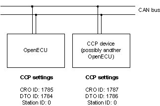
Here, both devices use different CRO and DTO message identifiers. This is enough to uniquely identify each device. Note that although each device has a station address of zero, because all CRO and DTO identifiers are unique, the station addresses could be any value.
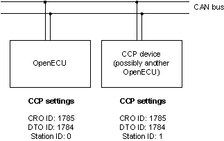
Here, both devices use the same CRO and DTO message identifiers so the station address is used to distinguish between CCP devices.
Section B.3.3, “Configuring two OpenECUs on the same CAN bus with ATI Vision” details how to connect ATI Vision and two ECUs for the first time. The procedure is similar for other tools.
If no configuration block exists in the model, CCP communications are disabled when the model is running. When reprogramming, the following default settings are used:
Table 6.3. CCP defaults
CCP setting Default value CRO message identifier 1785 DTO message identifier 1784 Station address 0 CAN bus identifier CAN 0 or CAN A CAN bus baud-rate 250kBps or 500kBps [a] [a] The default baud-rate for CCP will depend on which version of firmware was flashed into the ECU. Standard ECUs (such as M220-000 or M250-000) typically use 500 kBps default baud rate, but note that the M461-000 uses 250 kBps. Refer to Section 6.3, “OpenECU software versioning” for details.
If a configuration block exists in the model but CCP communications are disabled then when reprogramming, the CCP settings from the configuration block are used.
If the hardware does not support the CAN bus selected, CCP communications will cease while the model is running and while reprogramming. In this case, the OpenECU device must be returned to Pi for reconditioning.
The platform software supports version 2.1 of the CCP standard (Table F.1, “Supported CCP commands” shows which commands are implemented).
Warning
OpenECU does not adhere to all the message timing characteristics listed by the CCP standard all the time (especially when the model being run pushes the CPU loading closer to 100%). Some calibration tools may raise an error or warning if it does not receive a rely to a command within a time
If the OpenECU module is not communicating to the calibration tool after a recently build model is flashed onto the ECU, then try following Appendix G, CCP troubleshooting guide to recover the ECU.
This block configures CCP DAQ rasters.
None (Main library). (See Section 1.3, “Licensed Features”.)
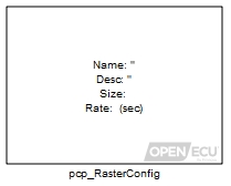
The CAN Calibration Protocol (CCP) is a CAN based messaging system designed to allow tools to access information in real-time. For more details, refer to ASAM Standards: ASAM MCD: MCD 1a at the ASAM Web site (http://www.asam.de).
Calibration tools can request the ECU transmit data on a periodic basis. OpenECU supports grouping data into at most 8 data acquisition lists (DAQs). The size and rate of each of these DAQs can be adjusted by this block.
Note
If there are no pcp_RasterConfig blocks in the application then the following default configuration is applied.
|
M220
M221 M250 M460 M461 | M670 | |
|---|---|---|
| Rate (milliseconds) | Size | Size |
| 10 | 15 | 30 |
| 100 | 15 | 30 |
| 200 | 15 | 30 |
| 1000 | 15 | 30 |
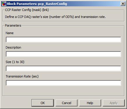
A unique name for the CCP DAQ raster. The name is written to the ASAP2 file and used by the calibration tool to identify the raster.
Value type: String Calibratable: No A description of the CCP DAQ raster's use.
Value type: String Calibratable: No The number of ODTs for the CCP DAQ raster. The total number of ODTs across pcp_RasterConfig blocks must not exceed the range given below. For instance, on the M670, it is permissible to have two pcp_RasterConfig blocks each with a size of 127. But adding a third pcp_RasterConfig with a size of 1 brings the total to 255, which exceeds the limit.
Range: [1, 254]
Value type: Integer Calibratable: No The suggested period between transmission of the CCP DAQ raster. Some calibration tools will use the suggested period (e.g., INCA) whilst other calibration tools will ignore the suggest period and allow the user to vary the transmission rate on the fly (e.g., Vision). One of 0.005, 0.010, 0.030, 0.050, 0.100, 0.200, 0.500, 1.000 seconds
Value type: Real Calibratable: No
Control whether seed/key security is required for CCP calibration, data acquisition and/or reprogramming.
None (Main library). (See Section 1.3, “Licensed Features”.)

To prevent third parties recalibrating or reprogramming modules, manufacturers typically enable CCP seed/key security for production modules. This requires a valid seed/key exchange to take place with the calibration tool, where the module generates a seed (usually at random) and the calibration tool must respond with the correct key value corresponding to that seed, calculated by a secret algorithm known to the module and the calibration tool.
To ensure that CCP seed/key security is also used during reprogramming mode, the functions used to generate the seed (if required) and validate the key are copied to non-volatile storage by the application. The reprogramming mode software retrieves the functions from non-volatile storage, and copies them to RAM for execution.
There are three CCP privilege levels: calibration, data acquisition, and programming. These privilege levels can be individually enabled or disabled. For instance, it is possible to enable reprogramming access whilst calibration and data acquisition access remains disabled. The calibration tool may impose further restrictions on how levels can be accessed.
CCP seed/key security is a standard feature of the protocol; however configuring it on different calibration/programming tools requires some knowledge of that tool's operation. Support will currently only be given for CCP seed/key security on PiSnoop (see Section B.2, “PiSnoop”), Vector CANape (see Section B.5, “Vector CANape”), and ATI Vision (see Section B.3, “ATI Vision”).
- Seed generator function
The seed generator function must be of the form:
void seed_generator(const U8 privilege_level, U8 *const seed)privilege_levelspecifies the privilege level for which a seed is being requested. Values are fixed by the CCP standard as:- 0x01 (1): Calibration
- 0x02 (2): Data acquisition
- 0x40 (64): Programming
seedis a four-byte array. This will initially contain values generated by a 32-bit random number algorithm within the OpenECU platform. The seed generator function may choose to leave these values intact, or may choose to set its own values in theseedarray.- Key validator function
The key validator function must be of the form:
BOOL key_validator(const U8 privilege_level, const U8 *const seed, const U8 *const key, const U8 key_size)privilege_levelspecifies the privilege level for which a seed is being requested.seedis a four-byte array containing the last seed value passed to the calibration tool.keyis an array of up to six bytes whose length is specified bykey_size. This contains the key passed back by the calibration tool.The CCP 2.1 specification for the CCP_UNLOCK command has a six-byte field for the key, although in practice most implementations only use four bytes. The contents of the remaining bytes are often undefined, so the key validator must take care to match the expected seed-key algorithm.
The function must return
TRUEif the key is valid for the seed, orFALSEif it is not.- Implementing seed/key functions
Because the seed generator and key validator functions will be relocated and run during reprogramming mode, it is ESSENTIAL that these functions do NOT access any global or static storage OR call any functions. If this is not the case, relocating and invoking the function in reprogramming mode will have unexpected consequences, because the function will read/write/execute memory at addresses which are not valid when in reprogramming mode. These consequences may include stuck outputs resulting in physical damage to hardware or electrical damage to the ECU, and/or complete permanent disablement of the ECU.
- Diab implementation considerations
If the application is built using the Diab compiler, then the file containing these functions should be specified for compilation as normal. It is frequently the case that seed/key functions are supplied only as object or library code for security reasons, in which case the file must have been compiled with PowerPC variable bit length (VLE) instructions.
- GCC implementation considerations
If the application is built using GCC, then the file containing these functions must also contain section attribute specifiers to place the code in sections that correspond to the names of the security functions. The attribute specifiers must be applied to the function prototypes in the form:
void seed_generator(const U8 privilege_level, U8 *const seed) __attribute__ ((section (".seed_generator")));It is frequently the case that seed/key functions are supplied only as object or library code for security reasons, in which case the file must have been compiled without PowerPC variable bit length (VLE) instructions.
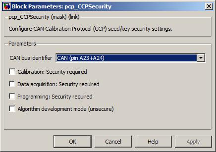
The CAN bus for which CCP security will be implemented. A pcp_CCPConfiguration block must also exist in the design which configures CCP for this CAN bus. If this does not exist, an error will be reported.
Value type: List Calibratable: No Whether CCP seed/key security is required for this CCP privilege level.
Value type: Boolean Calibratable: No ECU seed generator function (optional)
If required, the name of the C function which generates the seed value. If this is not specified, a random 4-byte value will be generated by the OpenECU platform and used as a seed instead.
Value type: String Calibratable: No The name of the C function which validates the key value transmitted by the calibration tool. If this is not specified, an error will be reported.
Value type: String Calibratable: No If required, the name of the DLL supplying the key generation algorithm for the calibration tool. This will typically only be required if the RTW build is required to generate ASAP2 (A2L) files to configure the calibration tool. If this is not specified, security will not be configured in the A2L files, although typically the user will still be able to configure security manually from within the calibration tool.
Value type: String Calibratable: No ASAP security DLL function (optional)
If required, the name of the function within the DLL supplying the key generation algorithm. If unspecified, this will default to using the ASAP1A/ASAP2 standard function name
ASAP1A_CCP_ComputeKeyFromSeed. Note that some calibration tools do not permit the function name to be specified; see the relevant section for the calibration tool to be used for further details.Value type: String Calibratable: No Algorithm development mode (unsecure)
Whether the ECU should ignore security algorithms when reprogramming mode is entered as a result of the module powering up with FEPS applied.
This option allows a security algorithm to be tested without the risk of putting the ECU in a state where it cannot be reprogrammed. Otherwise, an error in the security algorithm will necessitate returning the ECU to Pi for servicing.
Value type: Boolean Calibratable: No
The file(s) containing seed generator and key validator functions must be referenced by the model. In Simulink, select the "Custom Code" option (found alongside other code generation/RTW model build options; the menu item depends on MATLAB version). If these functions are provided as uncompiled C, add the files to the list of "Include list of additional: Source files". If these functions are provided as precompiled object or library files (as is frequently done for security reasons), add them to the list of "Include list of additional: Libraries". RTW will then compile (if necessary) and link these files as part of the build.
Note that if incorrect function names are specified for seed generator or key validator functions, if the functions do not have the correct prototype, or if the relevant files are not compiled/linked in the model, then the build will fail at the link stage. If this occurs, check that function names and file names are specified correctly.
Control whether reprogramming can occur via CCP when the application is running.
None (Main library). (See Section 1.3, “Licensed Features”.)
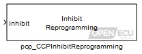
It is often useful to be able to disallow reprogramming of the module when performing certain actions, e.g., controlling an engine. Use this block to specify when reprogramming is allowed.
When disallowed, the following CCP operations will not be honoured (but other implemented CCP operations are; see Table F.1, “Supported CCP commands” for a complete list of supported CCP commands):
| CCP Command | Identifier |
|---|---|
| CLEAR_MEMORY | 16 |
| SELECT_CAL_PAGE | 17 |
| PROGRAM | 24 |
| MOVE | 25 |
| DIAG_SERVICE | 32 |
| ACTION_SERVICE | 33 |
| PROGRAM_6 | 34 |
If the block is not included by an application in a model, then reprogramming is allowed by default.
Warning
If the application is configured to inhibit reprogramming it may require the module to be powered up with FEPS applied in order to re-flash the module.
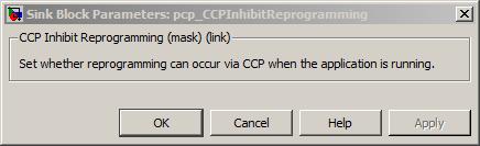
Get the number of CCP CRO messages received since the last reset.
None (Main library). (See Section 1.3, “Licensed Features”.)
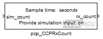
The platform CCP drivers keep track of various statistics, including the number of CRO messages received by the driver.
Only used during simulation. The value of this inport will be passed to rx_count. Only available if the mask parameter Provide simulation input is checked.
Range: [0, 4294967295] messages
Value type: Integer
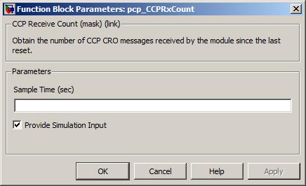
The periodicity of the block execution.
Range: [0.001, 3600] seconds
Value type: Real Calibratable: No If selected then simulation inport sim_count is made available.
Value type: Boolean Calibratable: No
Specify or append compiler options when building a model.
None (Main library). (See Section 1.3, “Licensed Features”.)
After RTW has generated code for a model, a compiler converts the code into a binary image suitable for the ECU to execute. Which compiler to use is chosen through the RTW Compiler Selection option.
The compiler converts the model code into a binary image using various transformations, some of which can be modified via command line options to the compiler. The pcomp_CompileOptions block selects whether to use the default compiler options supplied with OpenECU, to add additional options to the default options, or to replace the default options altogether.
Warning
Alteration of the compiler options may lead to a model which fails to build, or a model which will not run on the target ECU or which may run initially but fail later on. When reporting a failure through technical support, please specify any changed compiler options as this may help resolve the issue more quickly.
- Diab 5.5.1.0
The default compiler options for the WindRiver Diab 5.5.1.0 compiler are:
Option Use -cproduce an object file only — do not attempt to link (OpenECU compiles each source file separately, then links each together, this is a required option) -DREAL_T=floatdefine RTW's real_T to be of 'float' type — this matches the hardware most closely and provides good performance, switching to 'double' will cause library incompatibility and slow down the model significantly -g3generate debug information as much as possible given the optimisations selected -Oturn on the compiler optimiser to reduce the binary image size and increase the run time efficiency -ew1551suppress errors about volatile qualification mismatch between RTW functions and calibrations -Xaddr-sconst=0x11ask the compiler to address all small data objects using absolute addressing (i.e., not relative addressing via r2 or r13) because the address range of the calibration data is too large for relative addressing — defensive measure only; not strictly necessary because the -Xsmall-constoption makes sure no data object is classed as small.-Xbss-common-offask the compiler to ensure that there is only one declaration of a variable (without initialisation) — ensure there are no separate objects for the same variable in different modules -Xdouble-avoidask the compiler to generate 32-bit floating point constants rather than 64-bit floating point constants to reduce size and increase run time efficiency -Xenum-is-intensure that C and C++ objects link using the same data type for enumerations — although not strictly necessary (and OpenECU does not yet support C++ code), it may be an issue for customer linked code -Xforce-prototypeslint like option to ensure all functions have been declared with a prototype — i.e., ensure we don't fall into the trap of implicit function declarations which don't match the actual function declaration -Xieee754-pedanticrequest that the compiler match, as closely as possible, the IEEE754 floating-point specification -Xkeep-assembly-fileask the compiler to keep the binary image representation — useful for diagnosing compiler problems -Xkeywords=0x08allow the use of the non-standard packed keyword to achieve better use of memory in some data structures -Xkill-reorder=0x08avoid a bug in some versions of the Diab C compiler which incorrectly applies peep-hole optimisation to instructions which should not be transposed in the binary image -Xmin-align=1allow the compiler to place some packed data on address boundaries which are not natural for some data types -Xname-const=.cal_secask the compiler to place all calibration variables in the same memory section for simple linking -Xpass-sourceask the compiler to output C source intermixed with the assembly instructions — useful for diagnosing compiler problems -Xsmall-const=0ask the compiler to avoid placing data objects in the small const data area (see also, -Xaddr-sconst)-Xstrict-eabiensure the compiler does not generate stswiandlswiinstructions-Xstsw-slowensure correct calling procedure for architecture across different object code — although not strictly required at the moment, this defines the object interface for other object code that may be linked to the final model e.g., custom code -t...set to -tPPCE200Z3VEFfor the M220 — selects the processor for the target ECU- Diab 5.8.0.0
The default compiler options for the WindRiver Diab 5.8.0.0 compiler are the same as Diab 5.5.1.0.
- Diab 5.9.0.0
The default compiler options for the WindRiver Diab 5.8.0.0 compiler are the same as Diab 5.5.1.0.
- All Diab compilers
The build mechanism also adds the following WindRiver Diab compiler options. These options cannot be changed.
Option Use -t...set to -tPPCE200Z3VEFfor the M220, M221, M250, M460 and M461 or set to-tPPCE200Z7VEFfor the M670 — selects the processor for the target ECU- GCC 4.7.3
Option Use -cproduce an object file only — do not attempt to link (OpenECU compiles each source file separately, then links each together, this is a required option) -DREAL_T=floatdefine RTW's real_T to be of 'float' type — this matches the hardware most closely and provides good performance, switching to 'double' will cause library incompatibility and slow down the model significantly -fkeep-static-constsemit variables declared static const when optimization isn't turned on, even if the variables aren't referenced -funsigned-charmatching the default signed-ness of charfor the Diab compiler and the platform library files-fno-commoncontrols the placement of uninitialized global variables — specifies that the compiler should place uninitialized global variables in the data section of the object file, rather than generating them as common blocks -g3generate debug information as much as possible given the optimisations selected -G 8put global and static objects less than or equal to num bytes into the small data or BSS sections instead of the normal data or BSS sections. The default value of num is 8. The -msdata option must be set to one of 'sdata' or 'use' for this option to have any effect. All modules should be compiled with the same -G num value. Compiling with different values of num may or may not work — if it doesn't the linker gives an error message -- incorrect code is not generated. -mcpu=e500mcselects the type of RX CPU to be targeted -meabialign the stack to an 8-byte boundary -membset the PPC EMB bit in the ELF flags header to indicate that 'eabi' extended relocations are used -mno-relocatablegenerate code that does not allow a static executable to be relocated to a different address at run time. A simple embedded PowerPC system loader should relocate the entire contents of .got2 and 4-byte locations listed in the .fixup section, a table of 32-bit addresses generated by this option -mno-relocatable-libgenerates a .fixup section to allow static executables to be relocated at run time -mregnamesgenerate 'in', 'loc', and 'out' register names for the stacked registers -msdataput small initialized const global and static data in the '.sdata2' section, which is pointed to by register r2. Put small initialized non-const global and static data in the '.sdata' section, which is pointed to by register r13. Put small uninitialized global and static data in the '.sbss' section, which is adjacent to the '.sdata' section -Oturn on the compiler optimiser to reduce the binary image size and increase the run time efficiency -pass-exit-codesreturn with the numerically highest error produced by any phase returning an error indication. The C front end returns 4 if an internal compiler error is encountered -x cuse the C language when compiling -Wno-attributesdo not warn if an unexpected __attribute__ is used, such as unrecognized attributes, function attributes applied to variables, etc. This will not stop errors for incorrect use of supported attributes -Wa,-alnask the compiler to keep the binary image representation — useful for diagnosing compiler problems - All compilers
The build mechanism also adds the following compiler options. These options cannot be changed.
Option Use -D...various RTW required macro definitions -DCFG_...defines the ECU the model is targeted at -I...various include paths for source files (model based, RTW based, compiler based and OpenECU based)
Note
Its outside the scope of this User Guide to explain all the different compiler options in detail and their resulting affect on the ECU binary image. Please refer to appropriate compiler User Guide for more information.
Note
Alteration of the compiler options may remove options which work around known bugs in the compiler. For a list of known bugs which affect OpenECU, see Section 2.5.9.2, “Known defects”, Section 2.5.10.2, “Known defects” and Section 2.5.11.2, “Known defects”, Section 2.5.12.2, “Known defects”.
Note
Various settings must be confirmed before the compiler is accessible to OpenECU. See the MATLAB command oe_check_compiler for more details.
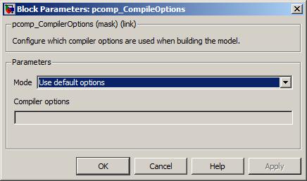
Whether to use the default compiler options, whether to add compiler options to the default options, or whether to replace the default options altogether.
Value type: List Calibratable: No The options to add to the default compiler options, or to replace the default options, as selected by parameter Mode.
Value type: String Calibratable: No
Configure Simulink to use the Embedded Coder auto-coder.
None (Main library). (See Section 1.3, “Licensed Features”.)

A utility block to switch the current active configuration set of RTW options for the RTW Embedded Coder auto-coder. See Section 4.3.2, “Auto-coders” for more.
Configure Simulink to use the Simulink Coder RTMODEL auto-coder.
None (Main library). (See Section 1.3, “Licensed Features”.)
A utility block to switch the current active configuration set of RTW options for the RTW RTMODEL auto-coder. See Section 4.3.2, “Auto-coders” for more.
Specific configuration for the M250 target ECU.
None (Main library). (See Section 1.3, “Licensed Features”.)
The pcfg_Config_M250 block configures pin A32, A33 and A34 to act as an injector output or as a PWM output. If the pin is configured as a PWM output, then the block can also configure the current trip level for each pin.
If the block is not present in a model, then the platform software configures pins A32, A33 and A34 as a PWM output with a current trip level of 5A during model initialisation.
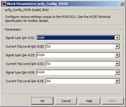
Specific configuration for the M460 target ECU.
None (Main library). (See Section 1.3, “Licensed Features”.)
The pcfg_Config_M460 block configures pin A31 to act as an injector output or as a PWM output. If the pin is configured as a PWM output, then the block can also configure the current trip level for pin A31.
If the block is not present in a model, then the platform software configures pin A31 as a PWM output with a current trip level of 5A during model initialisation.
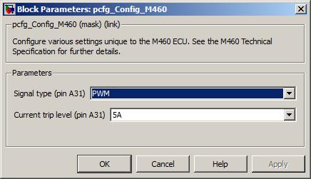
The output type for pin A31, either injector output or PWM output.
The current trip level above which the output will turn itself off, if the output has been configured as PWM (the current trip level has no effect when the output is configured as injector).
Specific configuration for the M670 target ECU.
None (Main library). (See Section 1.3, “Licensed Features”.)
The pcfg_Config_M670 block configures pins Y20, Y21, and Y43 to set the resolution of those frequency inputs.
If the block is not present in a model, then the platform software configures the pins to the default slow clock setting.
For MIOS-controlled digital I/O, multiple clock speeds can be chosen:
Slow clock: 4.125Mhz timebase.
Medium Clock: 8.25Mhz timebase. For inputs 0.75 Hz to 2500 Hz with a minimum resolution of at least 0.5 Hz
Fast Clock: 16.5Mhz timebase. For inputs 1.6 kHz to 60 kHz with a minimum resolution of at least 218 Hz.
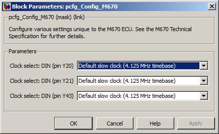
Drive the output channel pin to a given current.
None (Main library). (See Section 1.3, “Licensed Features”.)
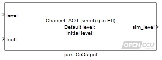
The constant current output block causes the channel pin to be driven to a requested current given by the level inport at every block iteration.
A value representing the percentage of the output current range to supply via the output channel. For instance, if the output pin range is 0A to 2A, then a value of 0.5 at this inport will request the hardware supply a constant current of 1A.
Range: [0, 1] unitless
Place a 1 here to force the block to use the parameter Default level for the output, 0 to use the inport level.
Range: 0 or 1
Only used in simulation. this outport is set to the requested current level (i.e., the inport level or the parameter Default level depending on the inport fault).
Range: [0, 1] duty-cycle
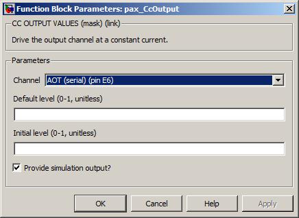
The channel pin for this constant current output.
Value type: List Calibratable: No This is the level for the constant current output when the fault inport is set to 1.
Range: [0, 1] unitless
This is the level of the constant current output prior to when the block is first executed.
Range: [0, 1] unitless
Tick to add simulation outports, untick to remove simulation outports.
Range: [0, 1] unitless
The periodicity of the block execution.
Range: [0.001, 3600] seconds
Configure a TLE8242-2 constant current output channel.
None (Main library). (See Section 1.3, “Licensed Features”.)
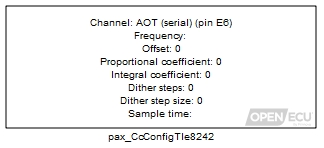
The current level is established with the pax_CcOutput block. Additional configuration specific to the TLE8242-2 is provided by this block. The configuration is applied at every block iteration.
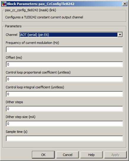
The channel pin for this constant current output.
Value type: List Calibratable: No Frequency of current modulation (Hz)
The desired frequency of the output. If the software cannot match the desired frequency, the frequency will be adjusted to as close a match as is possible.
Range: [10.5, 4000] Hz
Value type: Real Calibratable: Yes, offline and online The desired phase offset of the output relative to the TLE8242-2 phase sync signal. If the offset is initialised to a non zero value, then the outputs will hold until the phase sync signal is pulsed. The phase sync signal may be pulsed during runtime to syncronise outputs. If the software cannot match the desired pulse offset, the offset will be adjusted to as close a match as possible within 1/32 increments of the pulse period.
Range: [0, 31/32 of pulse period] ms
Value type: Real Calibratable: Yes, offline and online Control loop proportional coefficient (unitless)
The desired proportional coefficient of the PI control loop that determines the duty cycle of the constant current output. The supplied value is passed directly to the TLE8242-2 KP register without scaling applied.
Range: [0, 4095] unitless
Value type: Integer Calibratable: Yes, offline and online Control loop integral coefficient (unitless)
The desired integral coefficient of the PI control loop that determines the duty cycle of the constant current output. The supplied value is passed directly to the TLE8242-2 KI register without scaling applied.
Range: [0, 4095] unitless
Value type: Integer Calibratable: Yes, offline and online The desired number of dither steps per 1/4 waveform. If the software cannot match the number of dither steps, the number of steps will be adjusted to as close a match as possible.
Range: [0, 31] steps per 1/4 dither cycle
Value type: Integer Calibratable: Yes, offline and online The desired dither step size. If the software cannot match the desired dither step size, the step size will be adjusted to as close a match as possible.
Range: [0, 500] mA
Value type: Integer Calibratable: Yes, offline and online The periodicity of the block execution.
Range: [0.001, 3600] seconds
Value type: Real Calibratable: No
The current level and configuration for a channel should be set in the same task to ensure data coherence.
The dither waveform is specified by the number of dither steps and the size of each step. Each output pulse advances the dither waveform by one step. The following diagram demonstrates the relationship between the pulse period, number of dither steps, and the dither step size.
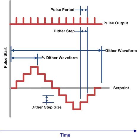
Each channel of the TLE8242-2 device includes a separate PI controller with programmable gain values KP and KI. The Infineon TLE7242 KI KP Application note describes a method to determine acceptable KP and KI values. A summary is included here; Please refer the the Infineon application note for additional details.
Acceptable KP and KI values may be determined by modeling the control system with a linear continuous time model.
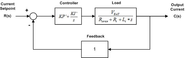
- Parameters required to calculate KP and KI
- VBAT
Supply voltage of the load.
- Rc
Resistance of the load.
- Lc
Inductance of the load measured at the pulse frequency.
- Rsense
Sense resistance value. This value is determined by the OpenECU hardware. It is 100 mR for all outputs.
- Fclk
Master clock frequency of the TLE8242-2 device. The frequency is set to 22 MHz by the OpenECU platform.
- FPWM
Pulse frequency of the output channel.
- Procedure to calculate KP and KI
- Determine Pulse Frequency
Set pulse frequency to the upper limit unless some constraint of the load requires it to be lower.
- Determine the damping ratio of the system
Start with 0.707. Increase toward 1 to reduce overshoot. Decrease to improve rise time. The damping ratio is denoted by zeta in the supplied equations.
- Determine the undamped natural frequency
Calculate according to equation 1. Decreasing will result in longer settling time and increased dither amplitude attenuation. Increasing will lead to poor matching of the linear model to the system.
- Calculate KP' and KI'
Calculate according to equations 2 and 3. If KP' is less than zero, then the pulse frequency is too low.
- Calculate KP and KI
Calculate according to equations 4 and 5. If KP or KI is greater than 4095, then the undamped natural frequency must be decreased.
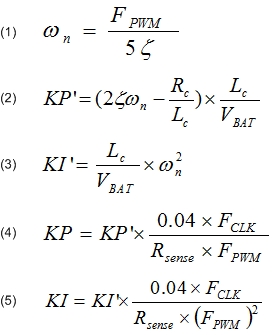
Command a TLE8242-2 constant current channel to autozero.
None (Main library). (See Section 1.3, “Licensed Features”.)
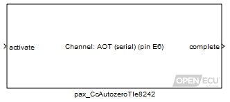
This block allow the application to initiate autozero of a TLE8242-2 device channel. The channel will be zeroed over the next four pulse periods. The current setpoint must be set to zero before triggering the autozero feature. TLE8242-2 channels cannot be autozeroed in parallel.
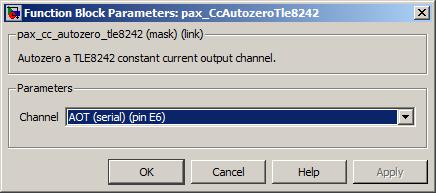
Reports current measurement for a TLE8242-2 channel.
None (Main library). (See Section 1.3, “Licensed Features”.)
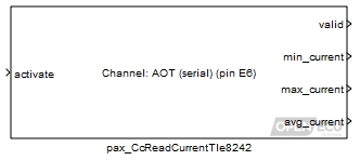
This block allow the application to read the current measurement values of a TLE8242-2 channel. The measurement is updated at the end of the next dither period. TLE8242-2 channels cannot be measured in parallel.
This outport is pulsed upon the completion of the measurement.
Range: 0 or 1
Value type: Boolean This outport reports the minimum current measured during the dither period. The output value is only valid while the valid output is asserted.
Range: [0, 2000] mA
Value type: Integer This outport reports the maximum current measured during the dither period. The output value is only valid while the valid output is asserted.
Range: [0, 2000] mA
Value type: Integer This outport reports the average current measured during the dither period. The output value is only valid while the valid output is asserted.
Range: [0, 2000] mA
Value type: Integer
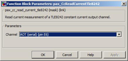
Output a new value of the debounced state only if the transient state has remained constant for a number of cycles.
None (Main library). (See Section 1.3, “Licensed Features”.)
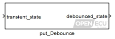
This block debounces the transient state over a number of cycles to produce a steady state output. The debounced state output only changes to reflect the transient state input if the input has remained steady for a number of cycles.
Unlike other blocks, the debounce is expressed in block iterations, rather than a time period. This makes the block more appropriate for debouncing state based signals than time based signals.
The debounced state. On the first iteration, the internal debounced state is set to the input transient_state.
Value type: Boolean Calibratable: No
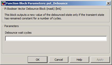
Set all DTCs referred to by the table identifier parameter, to the clear state, if the clear state is supported by the DTC.
None (Main library). (See Section 1.3, “Licensed Features”.)
For the DTCs with matching type to the parameter DTC type in the DTC table specified by parameter DTC table identifier, this block sets the DTC state to clear. See the pdtc_DiagnosticTroubleCode and pdtc_DiagnosticTroubleCodeExt blocks for details about the states each type of DTC can have.
Freeze frame data associated with the cleared DTCs is also cleared. Monitor (DME and DTE) data is also cleared other than persistent data which is never cleared (e.g. numerators and denominators). As the platform does not know which DME/DTE objects are associated with which DTCs in an application, it is assumed that the table being cleared applies to all emissions-relevant monitors.
This is suitable for running in response to a J1939 DM11 request in OBD systems.
Set to 1 to force the state of each DTC, with matching type to that specified by parameter DTC type, to clear. Otherwise, set to 0 for no change in DTC states.
Value type: Boolean Calibratable: No
The name of the DTC table to act on (there must be a corresponding named table specified in a pdtc_Table block in the model).
Value type: String Calibratable: No A drop-down selection of the type of DTC to act on in the DTC table specified by parameter DTC table identifier.
Value type: List Calibratable: No
Set all DTCs referred to by the table identifier parameter, to the clear state, if the clear state is supported by the DTC, and if the DTC state is currently active.
None (Main library). (See Section 1.3, “Licensed Features”.)
For the DTCs with matching type to the parameter DTC type in the DTC table specified by parameter DTC table identifier, this block sets the DTC state to clear, if the DTC state is currently active. See the pdtc_DiagnosticTroubleCode and pdtc_DiagnosticTroubleCodeExt blocks for details about the states each type of DTC can have.
Freeze frame data associated with the DTCs cleared is also erased, but not monitor data.
For OBD systems, see also pdtc_ClearAll.
Set to 1 to force the state of each DTC, with matching type to that specified by parameter DTC type, to clear if it is currently active. Otherwise, set to 0 for no change in DTC states.
Value type: Boolean Calibratable: No
The name of the DTC table to act on (there must be a corresponding named table specified in a pdtc_Table block in the model).
Value type: String Calibratable: No A drop-down selection of the type of DTC to act on in the DTC table specified by parameter DTC table identifier.
Value type: List Calibratable: No
Set all DTCs referred to by the table identifier parameter, to the clear state, if the clear state is supported by the DTC, and if the DTC state is currently "inactive" or "previously active".
None (Main library). (See Section 1.3, “Licensed Features”.)
For the DTCs with matching type to the parameter DTC type in the DTC table specified by parameter DTC table identifier, this block sets the DTC state to clear, if the DTC state is currently "inactive" or "previously active". See the pdtc_DiagnosticTroubleCode and pdtc_DiagnosticTroubleCodeExt blocks for details about the states each type of DTC can have.
Freeze frame data associated with the DTCs cleared is also erased, but not monitor data.
This is intended to be used in response to a J1939 DM3 request, which but the standard warns that that service is not intended for clearing diagnostic data in regulated OBD products. See also pdtc_ClearAll.
Set to 1 to force the state of each DTC, with matching type to that specified by parameter DTC type, to clear if it is currently inactive. Otherwise, set to 0 for no change in DTC states.
Value type: Boolean Calibratable: No
The name of the DTC table to act on (there must be a corresponding named table specified in a pdtc_Table block in the model).
Value type: String Calibratable: No A drop-down selection of the type of DTC to act on in the DTC table specified by parameter DTC table identifier.
Value type: List Calibratable: No
Set the state and auxiliary data about a diagnostic trouble code.
None (Main library). (See Section 1.3, “Licensed Features”.)
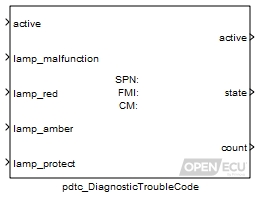
A diagnostic trouble code (DTC) is a unique indicator used to remember the state of a fault. The model determines if the conditions for signalling the fault are satisfied or not, and passes this information to the pdtc_DiagnosticTroubleCode block. Whether the fault is active or not, is maintained by the block while the model is running and across power cycles (see the pdtc_Memory block for more details).
There is only one type of DTC at the moment, more may be added in the future.
- J1939 DTC
The J1939 DTC maintains a fault state and a count of the how many times the DTC has become active. The J1939 DTC states follow this state diagram:
The DTC starts in the clear state (or whichever state was recalled from non-volatile memory during power up, see the pdtc_Memory block for more details), and remains in this state until the inport active becomes 1. The block then changes the DTC state to active and remains in this state until the inport active becomes zero. And so on.
Outwith this diagram pictured above, the DTC state can be forcefully set to clear through the use of the pdtc_ClearAll block, or pdtc_ClearAllIfActive block, or pdtc_ClearAllIfInactive block.
If the DTC cannot be recalled from non-volatile memory (which includes the first time the ECU is powered up), then the J1939 DTC is initialised as follows:
DTC information Initial value State Clear Count 0 Lamp malfunction 3 Lamp red 3 Lamp amber 3 Lamp protect 3
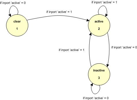
Set to 1 if the dtc is active, set to zero otherwise. Available only if the parameter DTC type is J1939 DTC.
Range: 0 or 1
Value type: Boolean Set to desired lamp state (0 is Slow Flash, 1 is Fast Flash, 2 is On, 3 is Off). Available only if the parameter DTC type is J1939 DTC.
Range: [0, 3]
Value type: Integer Set to desired lamp state (0 is Slow Flash, 1 is Fast Flash, 2 is On, 3 is Off). Available only if the parameter DTC type is J1939 DTC.
Range: [0, 3]
Value type: Boolean Set to desired lamp state (0 is Slow Flash, 1 is Fast Flash, 2 is On, 3 is Off). Available only if the parameter DTC type is J1939 DTC.
Range: [0, 3]
Value type: Boolean Set to desired lamp state (0 is Slow Flash, 1 is Fast Flash, 2 is On, 3 is Off). Available only if the parameter DTC type is J1939 DTC.
Range: [0, 3]
Value type: Boolean
Set to 1 if the dtc is in the active state, set to zero otherwise. Available only if the parameter DTC type is J1939 DTC.
Value type: Boolean Set to the value of the current DTC state (see the DTC types descriptions for a list of states and values). Available only if the parameter DTC type is J1939 DTC.
Value type: List A count of the number of times a DTC has changed to the active state. Available only if the parameter DTC type is J1939 DTC.
Range: [0, 127]
Value type: Integer
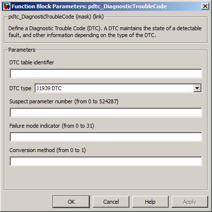
The name of the DTC table to store this DTC in (there must be a corresponding named table specified in a pdtc_Table block in the model).
Value type: String Calibratable: No A drop-down selection of the type of the DTC.
Value type: List Calibratable: No The value of the SPN for this DTC. The parameters Suspect parameter number, Failure mode indicator and Conversion method uniquely identify the DTC. Available only if the parameter DTC type is J1939 DTC.
Range: [0, 524287]
Value type: Integer Calibratable: No The value of the FMI for this DTC. The parameters Suspect parameter number, Failure mode indicator and Conversion method uniquely identify the DTC. Available only if the parameter DTC type is J1939 DTC.
Range: [0, 31]
Value type: Integer Calibratable: No The value of the CM for this DTC. The parameters Suspect parameter number, Failure mode indicator and Conversion method uniquely identify the DTC. Available only if the parameter DTC type is J1939 DTC.
Range: 0 or 1
Value type: Integer Calibratable: No
Allows an application to enable or disable periodic processing of the pdtc lamp status.
None (Main library). (See Section 1.3, “Licensed Features”.)
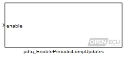
By default, the platform software will periodically determine the appropriate lamp status by examining the state of all DTCs in all tables. For applications with a large number of DTCs, this processing can take a significant amount of time.
This block allows an application to programmatically disable and enable this processing.
Retain the DTC tables in non-volatile storage across power cycles.
None (Main library). (See Section 1.3, “Licensed Features”.)
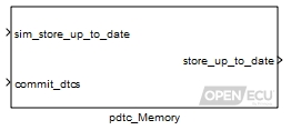
The pdtc_Memory block stores the DTC table data in non-volatile memory. On start-up, the block attempts to retrieve the DTC table data prior to running the model. While the model is running, the time at which the DTC table is stored back to non-volatile memory is determined by the model itself.
The DTC table data is check-summed using a 16-bit CRC. Failure to match the check-sum against the table data on start-up means that the data cannot be recovered. In this case, DTC table data is reverted to the default start-up conditions for each type of DTC (see the pdtc_DiagnosticTroubleCode and pdtc_DiagnosticTroubleCodeExt blocks for specifics).
When an application is programmed onto the ECU, any pre-existing DTC data (and any related diagnostic information) are cleared if the model version number differs from what was previously programmed. However, if the model version number remains the same, and the total number of DTCs in the model also remains the same, then the pre-existing DTCs are retained. The model version number is specified through the put_Identification block.
This block is used to update the check-sum and write the DTC table data to non-volatile store. When the inport commit_dtcs is set to 1, the block pauses execution of the model, calculates the DTC table data check-sum, stores the DTC table data in non-volatile memory, then continues execution of the model.
Note
When the block pauses the model execution, the length of pause depends on the store location. Storage in battery backed RAM will result in a short pause, storage to Flash will result in a longer pause.
Old DTC data is reused so long as it has the expected total data size and was written by an application with the same user-specified version number. Otherwise the values revert to defaults. If the usage of DTC blocks has changed in a new software version, increase the application sub-minor version number to ensure that any old values are not used, as they may not map appropriately to the blocks in the new model even if the total data size happens to match.
It is important to trigger the commit and not update any diagnostic trouble code thereafter before shutting down the ECU. If diagnostic trouble code data is modified after the check-sum has been updated, and the ECU shuts down, next time it powers up, diagnostic trouble code data will revert to default.
To ensure the check-sum is up to date before shutting down the ECU, the store_up_to_date outport provides an indication of whether the check-sum is correct or not. If not, shutdown of the module can be prevented (if conditions are appropriate) and the store updated (by setting the commit_dtcs inport to 1).
Simulation value for the outport store_up_to_date.
Range: 0 or 1
Value type: Boolean Calibratable: No Set to 1 to update the check-sum for the DTC tables and to write the result to non-volatile memory. Set to zero otherwise.
Range: 0 or 1
Value type: Boolean Calibratable: No
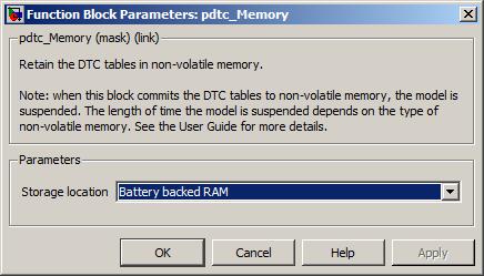
Declares a table of diagnostic trouble codes (DTCs), that can be referred to by other blocks that wish to refer to a group of DTCs.
None (Main library). (See Section 1.3, “Licensed Features”.)
The pdtc_Table groups together DTCs into one table. The table can then be worked on by other blocks (for instance, the pdtc_ClearAll block or the pj1939_Dm1Transmit block) and stored in non-volatile memory (see the pdtc_Memory block).
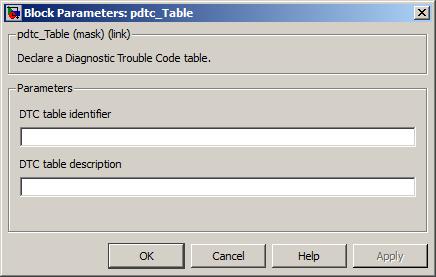
Output the state of a digital input pin after debounce logic.
M110-000, M110-000, M220-000, M220-0AU, M220-000, M220-0AU, M221-000, M221-000, M250-000, M250-000, M460-000, M460-000, M461-000, M461-000, M670-000 and M670-000
None (Main library). (See Section 1.3, “Licensed Features”.)
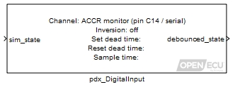
The digital input block reads a raw input digital value of 0 if the pin identified by the mask parameter Channel is at a logic low state or 1 if the pin is at a logic high state. The block is also capable of inverting and debouncing a signal.
If the mask parameter inversion is set to 1 then a logical NOT operation is applied to the input value before further processing. Otherwise it is passed through unchanged.
Debouncing can be achieved by setting mask parameters Set dead time and Reset dead time. On the first iteration of the block, the debounced_state outport is set to the value of the digital input (or the sim_state inport under simulation).
Only used in simulation. when the model is simulated, the outport debounced_state is set to the value of this inport.
Range: 0 or 1
Value type: Boolean Calibratable: No
1 if the raw input digital value has been high for at least Set dead time, 0 if the raw input digital value has been low for at least Reset dead time.
Range: 0 or 1
Value type: Boolean Calibratable: No
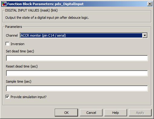
The channel pin for this digital input.
Value type: List Calibratable: No If inversion is ticked then a logical NOT operation is applied to the input value before further processing.
Value type: Boolean Calibratable: No The time the input will have to be high, before the block switches its output from 0 to 1. A value of zero is acceptable. A negative value has the same effect as a zero value.
Value type: Real Calibratable: Yes, offline and online The reset dead time is the time the input will have to be low, before the block switches its output from 1 to 0. A value of zero is acceptable. A negative value has the same effect as a zero value.
Value type: Real Calibratable: Yes, offline and online The periodicity of the block execution.
Range: [0.001, 3600] seconds
Value type: Real Calibratable: No Tick to enable inport sim_state.
Value type: Boolean Calibratable: No
Set the output channel pin high or low.
M110-000, M110-000, M220-000, M220-0AU, M220-000, M220-0AU, M221-000, M221-000, M250-000, M250-000, M460-000, M460-000, M461-000, M461-000, M670-000 and M670-000
None (Main library). (See Section 1.3, “Licensed Features”.)
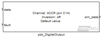
The digital output block causes the channel pin to be taken high or low depending on the state inport at every model iteration.
The channel logical state can be inverted with respect to the input in order to achieve the desired logical output state by setting the mask parameter Inversion.
The block also has a mechanism to set the output to a default value in two situations: at start-up; or if the fault indicator is active. The default output value is mapped directly to the channel pin logical state and is never inverted.
Place a 1 here to set the output channel pin high, place a 0 here to set the output channel pin low.
Range: 0 or 1
Value type: Boolean Calibratable: No Place a 1 here to force the block to use the default value for the channel pin state, otherwise place a 0 here to force the block to use the inport state as the channel pin state.
Range: 0 or 1
Value type: Boolean Calibratable: No
Only used in simulation. this outport is set to the requested channel pin state (i.e., state or the default state).
Range: 0 or 1
Value type: Boolean Calibratable: No
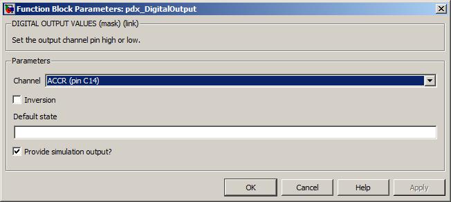
The channel pin for this digital output.
Value type: List Calibratable: No Inverts the mapping of the input value to the channel pin. If inversion is set to 1 then a logical NOT operation is applied to the input value before further processing.
Range: 0 or 1
Value type: Boolean Calibratable: No This sets the output to the default state in two situations: at start-up time, before this block has been executed in the first model iteration; and if a fault indicator is associated with the output and the fault is active. The value is mapped directly to the channel pin logical state and is never inverted.
Range: 0 or 1
Value type: Boolean Calibratable: Yes, offline and online Tick to enable outport sim_state.
Value type: Boolean Calibratable: No
Monitor the response of a digital output.
None (Main library). (See Section 1.3, “Licensed Features”.)
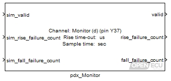
This block allows an application to determine whether or not the state of a digital output has changed as requested within the expected response time. It works by recording the time at which the output function requests a change of state, and then reading the actual state observed on the feedback input at a specific time later. If the actual state does not match the expected state, then a failure is noted. Independent counts of failures to fall and failures to rise are maintained and made available to the application via the outputs from this block.
The block is only available for certain low-side outputs and there are important differences between the falling edge and rising edge cases.
Falling edge: When a low-side output is activated, it is connected to ground within the ECU, and the potential on the pin should drop rapidly to ground potential. Under normal conditions, the time for the potential to fall is largely independent of the load on the pin. Failure of the potential to drop within the expected time indicates a low resistance path to a higher potential on the pin. This will result in a large current draw, causing the output device to get hot and turn off. If the platform software detects that the monitor feedback has not gone low within the expected time, it deactivates the output. The time threshold for the output to go low is hard-coded within the platform software. (See the technical specification of the target ECU for details.) The application can re-enable any disabled outputs using the pss_OvercurTripReset block.
Rising edge: When a low-side output is de-activated, it is disconnected within the ECU, and the potential on the pin should move in the direction of the high-side potential. How fast it does so will depend on the resistance between the pin and the high-side potential, i.e. the resistance of the load. Therefore the time threshold must be specified by the application via the Rise time-out mask parameter of this block. If the potential fails to rise within the expected time, this may indicate an open circuit on the pin, or a short-circuit to ground. Advice on what thresholds to set for different loads is given in the technical specification of the target ECU. The platform software takes no independent action in the case of such a fault being detected beyond reporting the fault count to the application.
Support for this block is restricted to certain types of output. Currently only spark outputs (using the pan_Spark block) and PWM outputs (using the pdx_PWMOutput or pdx_PWMVariableFrequencyOutput blocks) support monitoring (and only on those channels that have the necessary internal feedback signals). If the block is used with some other function on the corresponding output channel, then the valid outport will return 0 (FALSE).
Note that output monitoring will occur on those channels that support it, where possible, regardless of whether or not the application includes a pdx_Monitor block. This means that outputs will be disabled if the corresponding monitor channels fail to go low within the expected time. The only case where such intervention will not take place is if the output function used does not support monitoring.
Only used under simulation. Under simulation, the value of this inport is passed through to the valid outport.
Range: 0 or 1
Value type: Boolean Calibratable: No Only used under simulation. Under simulation, the value of this inport is passed through to the rise_failure_count outport.
Range: [0, 16777215]
Value type: Integer Calibratable: No Only used under simulation. Under simulation, the value of this inport is passed through to the fall_failure_count outport.
Range: [0, 16777215]
Value type: Integer Calibratable: No
Set to 0 when there is a configuration error, most probably due to an output function being used on this channel that does not support monitoring.
Range: 0 or 1
Value type: Boolean Calibratable: No A count of the number of times that the output state did not go high within the time specified by the Rise time-out mask parameter, since the ECU was powered on or reset.
Range: [0, 16777215]
Value type: Integer Calibratable: No A count of the number of times that the output state did not go low within the allowed time, since the ECU was powered on or reset.
Range: [0, 16777215]
Value type: Integer Calibratable: No
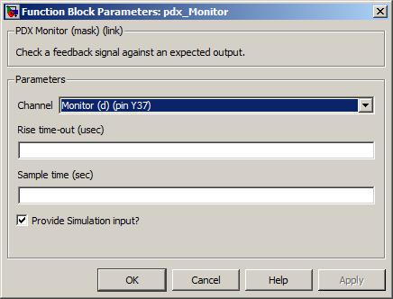
The channel pin to monitor.
Value type: List Calibratable: No The time within which the potential on the output pin is expected to go high after the output is deactivated.
Range: [0, 2000000] microseconds
Value type: Real Calibratable: Yes, offline and online The periodicity of the block execution.
Range: [0.001, 3600] seconds
Value type: Real Calibratable: No Tick to enable simulation inports sim_valid, sim_rise_failure_count and sim_fall_failure_count.
Value type: Boolean Calibratable: No
Read the value of a digital data input.
None (Main library). (See Section 1.3, “Licensed Features”.)
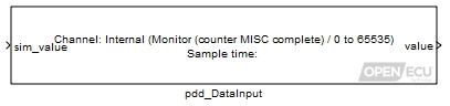
The digital data input block is a generic interface for reading a input channel that specifies numerical integer data. The units and interpretation of the value depends on the Channel being read.
Only used under simulation when the parameter Provide simulation input? is ticked. The outport value is written using the value of this inport.
Range: [-2147483648, 2147483647].
Value type: Integer
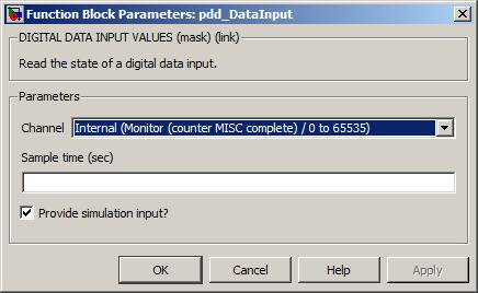
The channel for this input.
Value type: List Calibratable: No The periodicity of the block execution.
Range: [0.001, 3600] seconds
Value type: Real Calibratable: No Tick to enable inport sim_value.
Value type: Boolean Calibratable: No
Debounce a transient fault signal into a confirmed fault signal using a leaky bucket algorithm.
None (Main library). (See Section 1.3, “Licensed Features”.)
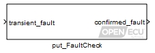
Debouncing of a transient fault signal is achieved using a leaky bucket algorithm. A leaky bucket integrator is used to decide when an input is confirmed as faulty as a function of its current state, which may be only transiently in error.
The bucket always has a total volume or depth of unity (1.0). When the input is deemed to be in error (e.g. out of range), water is poured into the bucket at some rise rate. At all times water flows out of a leak in the bottom of the bucket with some fall rate until it is empty. If the bucket should ever fill to the brim by reaching a depth greater than or equal to 1.0, the input is confirmed as faulty. Should the bucket subsequently empty to below its hysteresis depth, it is no longer confirmed as faulty.
Result of processing transient_fault through a leaky bucket algorithm over a number of block iterations.
Range: 0 or 1 (no fault, fault)
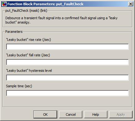
Rate at which leaky bucket is filled when input is faulty in some respect.
Range: [0, 1000] /sec
Rate at which leaky bucket is emptied if it is not already empty.
Range: [0, 1000] /sec
Level below which bucket depth must fall before fault is no longer considered faulty. If set to a negative value, fault remains latched. As a special case, if the hysteresis depth is set negative, should the input ever reach a confirmed fault state it remains "latched" there until the ECU device is powered down.
Range: [-inf, inf] unitless
The periodicity of the block execution.
Range: [0.001, 3600] seconds
Value type: Real Calibratable: No
Output the last measured frequency.
None (Main library). (See Section 1.3, “Licensed Features”.)
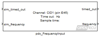
The frequency measurement block, measures the duration of each pulse in a pulse train from an input signal and determines the frequency of that pulse. The last measured frequency is provided as an outport.
If a frequency has not been measured (because a complete signal pulse has not yet occurred), then the corresponding frequency outport is clamped to zero.
If the input signal does not complete a pulse for longer than the block's timeout value, then the timed_out outport of the block is set. When a timeout occurs, the frequency outport remains at its last known value.
Only used in simulation. Place 1 here to simulate a time out, 0 otherwise.
Range: 0 or 1
Value type: Boolean Only used in simulation. Place the frequency in hertz here to simulate the last measured frequency. A measurement of zero hertz indicates that no measurement is available.
Value type: Real
1 if the input signal has not completed a pulse within the mask parameter timeout period at the point of sampling (see the mask parameter section below), 0 otherwise.
Range: 0 or 1
Value type: Boolean The last measured frequency in hertz, or 0 if no measurement has been taken (regardless of the state of outport timed_out). The range of the frequency is limited in various ways.
The range of the frequency that can be measured is limited by the filter circuitry of the input pin.
The lowest measurable frequency is limited by the filter circuitry and the size of the corresponding processor timer for a channel. Any input frequency below the documented limit, is reported as timed-out.
The highest measurable frequency is limited by the filter circuitry and the resolution of the corresponding processor timer for a channel. In general, the block reports the frequency of the filtered signal and the input filtering forms an upper limit. However, as the frequency increases, the resolution of measurement decreases.
Details of the input pin's filtering and processor timing can be found in an ECU's technical specification.
Range: [0.5, ...] Hz (for all targets)
Value type: Real
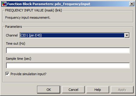
The input pin sourcing the signal to measure.
Value type: List Calibratable: No The period of time in hertz after which if no complete pulse has been measured, the outport timed_out is set to 1.
Range: [0.5, 10000] Hz (for all targets)
Value type: Real Calibratable: Yes, offline and online The periodicity of the block execution.
Range: [0.001, 3600] seconds
Value type: Real Calibratable: No If selected then create simulation inports for each of the outport message signals.
Value type: Boolean Calibratable: No
Measure the position, direction, and speed of a 3 phase hall input.
None (Main library). (See Section 1.3, “Licensed Features”.)

This block decodes pulse trains from a 3 phase hall input, such as a BLDC motor, and outputs details such as direction, position, and speed.
The pulse train, in a 3 phase hall encoder, is generated from three sensors that are either spaced 120° or 60° apart, depending on the sensor configuration. The hall decode block takes this pulse train and measures the A, B, and C channels determining the direction at each pulse and also counts the number of pulses. If the encoder is turning forwards then for each edge on the A, B, and C channels the block increments the count. If the encoder is turning backward then for each edge on the A, B, and C channels the block decrements the count. When the block iterates, it outputs the cumulative count of pulses since initialization and overflows/underflows on saturation.
The block also measures the duration of each pulse from the encoder's A, B, and C channels and outputs the last measured frequency of the last channel. If the frequency of a channel has not been measured (because a complete signal pulse has not yet occurred), then the corresponding frequency outport is set to zero.
If the block's A, B, and C channels do not complete a pulse for longer than the block's timeout value, then the timedout outport block is set. When a timeout occurs, the frequency outport for that channel remains at its last known frequency measurement (or zero if a measurement has not been completed).

There are two configurations that the hall sensors can be in, they can either be spaced 60° apart or 120° apart. When the sensors are 60° apart the signals outputted from the sensors across the three channels are 60° out of phase (i.e. the rising edge of each channel is 60° apart from one another). However, in order for this to be true the sector configuration around a stator of a motion system must be defined as shown in Figure 6.4, “Sector configuration for a 3 phase hall input - 60° spacing”, where the rotation of the sectors happen in the sequence of 0, 4, 6, 7, 3, 1, 0, 4, ... and so on. They are arranged in this fashion so that when the stator makes a revolution the hall sensor waveforms are generated with the correct spacing.
A sector is a 3 bit value that is used to determine the position of the motion system as detected by the sensors. Each bit in the sector equates to the pin state of each phase, the encoding of this value is shown in Figure 6.5, “Sector output encoding”.

As mentioned previously, for a 3 phase hall input there are only 6 possible sector values and as such each sector, consequently, has a width of 60°. In the 60° sensor spacing configuration each sensor is therefore only placed one sector after the other. The labels A, B, and C in Figure 6.4, “Sector configuration for a 3 phase hall input - 60° spacing” show this placing of sensors.
The output of the sensors is dependent on the sectors that passes through them. For example, if the output for sector 6 is being determined, sensor A will go low while sensors B and C will go high. This is because following the bit representation in Figure 6.5, “Sector output encoding”, bit 0 and 1 are high which correspond to the sensor states of phase B and C. Similarly, if sector 1 is being measured, sensor A will output high while sensor B and C will be low. Figure 6.6, “Sensor outputs with 60° spacing” below, shows the output of all 3 sensors across one full revolution with each signal being 60° out of phase.

Furthermore, if the sensor configuration is changed and they are spaced 120° apart, instead of the sensors being 1 sector apart they are 2 sectors apart, as each sector is 60° wide. Just as it was the case for the 60° spacing configuration, in order for the sensor outputs to be 120° out of phase the sectors must be pre-defined in a specific way. This configuration is shown below, in Figure 6.7, “Sector configuration and outputs for 120° sensor spacing”, along with the sensor outputs and the new sector sequence of 4, 6, 2, 3, 1, 5, 4, 6, and so on.

Only used in simulation. When the model is simulated, the outport direction is set to the value of this inport.
Range: 0 or 1
Only used in simulation. When the model is simulated, the outport sector is set to the value of this inport.
Range: [0, 7]
Only used in simulation. When the model is simulated, the outport revolution_frequency is set to the value of this inport.
Range: [0.5, ...] Hz
Only used in simulation. When the model is simulated, the outport revolution_counter is set to the value of this inport.
Range: [0, 16777215] counts
Only used in simulation. When the model is simulated, the outport sector_frequency is set to the value of this inport.
Range: [0.5, ...] Hz
Only used in simulation. When the model is simulated, the outport sector_counter is set to the value of this inport.
Range: [0, 16777215] counts
Only used in simulation. When the model is simulated, the outport timedout is set to the value of this inport.
Range: 0 or 1
The measured direction of the 3 phase hall input.
Range: 0 or 1
Note
The direction determines the sequence of the edges across channels. For example, if the direction is 1 and the sequence of edges for a motor with 60° spaced sensors is C, B, and A (as shown in Figure 6.6, “Sensor outputs with 60° spacing”) then when the direction is 0 the sequence will be reversed to A, B, and C.
The measured sector of the 3 phase hall input. A sector represents the position of the motion system.
Range: [0, 7]
Note
See Figure 6.4, “Sector configuration for a 3 phase hall input - 60° spacing” and Figure 6.7, “Sector configuration and outputs for 120° sensor spacing” for the pre-defined sector configurations for 60° spaced and 120° spaced sensors, respectively.
The measured revolution frequency of the overall 3 phase hall input. The frequency is measured from the last rising/falling edge to the current edge (of the same channel), as shown in the Figure below.

Range: [0.5, ...] Hz
The count of electrical revolutions seen by the 3 phase hall input. The revolution counter is only updated during phase A. It is increased when the direction is 1, and decreased when the direction is 0.
Range: [0, 16777215] counts
The measured sector frequency between phases of the 3 phase hall input, updated by the last phase. It is measured from the last edge, on any channel, to the current edge; see Figure below.

Range: [0.5, ...] Hz
The count of sectors seen by the 3 phase hall input. The sector counter is updated on every sector. It is increased when the direction is 1, and decreased when the direction is 0.
Range: [0, 16777215] counts
Set to 1 if the 3 phase hall input input signal has timed out when the block is iterated. If between iterations, the input signal timed out and then re-established itself, the time out event is not registered.
Range: 0 or 1

The input pin to measure for phase A of the 3 phase hall input.
Value type: List Calibratable: No Inverts the mapping of the input value to the channel pin.
Value type: Boolean Calibratable: No The input pin to measure for phase B of the 3 phase hall input.
Value type: List Calibratable: No Inverts the mapping of the input value to the channel pin.
Value type: Boolean Calibratable: No The input pin to measure for phase C of the 3 phase hall input.
Value type: List Calibratable: No Inverts the mapping of the input value to the channel pin.
Value type: Boolean Calibratable: No The sensor configuration to use for the 3 phase hall input, either 60° or 120° spacing.
Value type: List Calibratable: No The period of time in hertz after which if no complete pulse has been measured for any channel, the corresponding outport timedout is set to 1.
Range: [0.5, 10000] Hz
The periodicity of the block iteration.
Range: [0.001, 3600] seconds
Drives the H-Bridge channel pins according to a mode at a variable frequency and duty-cycle.
None (Main library). (See Section 1.3, “Licensed Features”.)
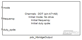
The H-Bridge output block drives a load connected between the two ECU pins in the desired mode. Four modes are provided allowing the H-Bridge output to have no drive (all switches open), brake (high-side switches closed), forward or reverse (one side is connected to high-side while the other is PWM'ed to ground at a programmable frequency and duty-cycle).
Warning
To avoid unexpected behavior, H-bridges should be set to NO DRIVE mode before flashing the ECU. This can be done by commanding the actuators to NO DRIVE any time the engine is not turning.
The duty-cycle used in forward and reverse mode is defined as the proportion of time where the load is driven (low-side switch is grounded).
The block supports 0% and 100% duty cycles.
Note
Some of the PWM output channels do not produce an accurate waveform when the duty cycle is either very small (e.g., 0.5%) or very large (e.g., 99.5%). All H-bridge output channels cope with 0% and 100% duty cycles correctly.
For the M250 target specifically, in order to avoid shoot-through and damage to the ECU when the mode switches, a 100us dead-time is inserted in the PWM signal for one task cycle at the beginning of mode-transition. Additionally, this dead-time insertion will only occur if the duty cycle that is commanded has a low time of less than 100us. For this reason, it will not be possible to command a 100% duty cycle during mode-transition for one task period. See diagram below for further detail.
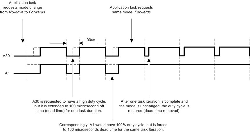
Mode in which the H-bridge will operate.
Range: [0, 3] respectively for No Drive / Brake / Forward / Reverse.
Value type: Integer Frequency of the PWM signal
Range: [0.5, 10000] Hz (for M220, M250 and M670 targets)
Value type: Real Ratio of the drive time to the signal cycle time.
Range: [0, 1] duty-cycle
Value type: Real Calibratable: No
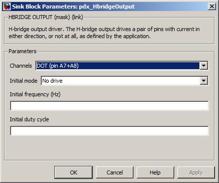
The pair of input pins sourcing the signal to measure.
Value type: List Calibratable: No The initial mode of operation used whilst the application is initialising.
Range: [No Drive, Brake, Forward, Reverse] (for M220, M250 and M670 targets)
Value type: List Calibratable: No The initial frequency used whilst the application is initialising.
Range: [0.5, 10000] Hz (for M220, M250 and M670 targets)
Value type: Real Calibratable: Yes, offline The initial duty cycle used whilst the appplication is initialising.
Range: [0, 1] duty-cycle
Value type: Real Calibratable: Yes, offline
Configure the ECU for J1939 communications.
None (Main library). (See Section 1.3, “Licensed Features”.)

The J1939 messaging protocol is a CAN based messaging system designed to pass information between vehicle network ECUs in real-time. For more details, refer to SAE J1939 (and sub-parts 21, 71, 73, 81) at the SAE Web site (http://www.sae.org).
The blockset supports a subset of the J1939 specification:
Handles requests for PGs by filtering out PGNs the model does not handle and returning NACK messages.
Handles reception and transmission of J1939 messages, in a similar way to the existing pcx_CANReceiveMessage and pcx_CANTransmitMessage blocks.
Handles the transport protocol (J1939/21) for sending long messages (up to 1785 bytes in length).
Handles some of the diagnostic requirements (J1939/73) for sending and receiving lists of diagnostic trouble codes (DM1 and DM2 messages). This includes support in the blockset for diagnostic trouble codes (see Section 4.6.6, “Fault support”).
Handles the network protocol (J1939/81) as if the ECU and the rest of the network have fixed network nodes.
Note
This may be extended in the future to include dynamic network addressing.
The pj1939_Configuration block configures the ECU's behaviour when handling J1939 messages. This block configures parameters that adjust the amount of memory set aside for processing J1939 messages.
The pj1939_Configuration block is used in conjunction with one or more pj1939_ChannelConfiguration block to configure the actual hardware interfaces and node addresses.
A pj1939_Configuration must be present in the model to enable J1939 support.
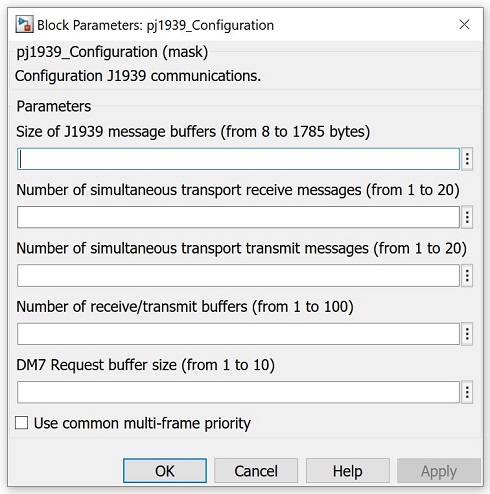
The number of bytes for each J1939 message buffer. In some networks, the maximum length of any received or transmitted J1939 message will be smaller than the maximum J1939 length of 1785 bytes. This parameter allows the modeller to reduce the amount of RAM allocated to J1939 messages, and therefore increase the RAM allocated to other functions of the ECU.
Range: [8, 1785]
Value type: Integer Calibratable: No Number of simultaneous transport receive messages
The number of long (transport) messages than can be received simultaneously. The smaller the number, the more RAM is allocated to other functions of the ECU.
These receive buffers are shared among all J1939 channels.
Range: [1, 20]
Note
The larger the number, the more transport messages can be received at the same time. However, the larger the number, the more likely it is that it will not be possible for the ECU to adhere to the J1939 transport timeouts and some message receives may fail.
Value type: Integer Calibratable: No Number of simultaneous transport transmit messages
The number of long (transport) messages than can be transmitted simultaneously. The smaller the number, the more RAM is allocated to other functions of the ECU.
These transmit buffers are shared among all J1939 channels.
Range: [1, 20]
Note
The larger the number, the more transport messages can be transmitted at the same time. However, the larger the number, the more likely it is that it will not be possible for the ECU to adhere to the J1939 transport timeouts and some message transmits may fail.
Value type: Integer Calibratable: No Number of receive/transmit buffers
The number of receive and transmit buffers per channel used to store J1939 CAN data between processing of J1939 messages (which occurs every 5 milliseconds).
Note that this is a count for each defined J1939 channel.
Range: [1, 100]
Value type: Integer Calibratable: No The maximum number of DM7 test entries that may be stored in the buffer, upon receipt of DM7 request messages.
This buffer is shared across all J1939 channels.
Range: [1, 10]
Value type: Integer Calibratable: No Use common multi-frame priority
A checkbox to enable the use of a common multi-frame priority. This priority overrides the priorities for all DM transmit blocks for multi-frame message responses. (Single frame responses are unaffected.) It does not affect any priorities passed to instances of the pj1939_PgTransmit block.
This setting applies to all J1939 channels.
Value type: Boolean Calibratable: No The value of the common multi-frame priority. Only available when the mask parameter checkbox Use common multi-frame priority is ticked.
This setting applies to all J1939 channels.
Range: [0, 7]
Value type: Integer Calibratable: No
Configure a J1939 communications channel.
None (Main library). (See Section 1.3, “Licensed Features”.)

OpenECU can support J1939 on any or all of the available CAN interfaces on an ECU. The pj1939_ChannelConfiguration block creates a J1939 channel to associate J1939 operations with a particular CAN interface. Each Individual J1939 operation specifies the J1939 channel with which the operation is associated.
The J1939_ChannelConfiguration block assigns a logical channel number to a particular CAN bus and configures the J1939 node name associaetd with that channel. Only one channel may be associated with a particular CAN interface.
See the pj1939_Configuration block for information about shared configuration items.
A model must have at least one pj1939_ChannelConfiguration block to utilize J1939.

The application-defined channel identifier.
Value type: Integer Calibratable: No A drop-down selection of CAN buses available for J1939 messaging.
Value type: List Calibratable: No The J1939 network node address for this ECU.
The automatically generated calibration parameter for this is
pj1939c_node_addr_0.Range: [0, 253]
Value type: Integer Calibratable: Yes, offline The name of the source ECU, given as a vector of 8 elements. The node name excludes the self-configuration field (see parameter Source self-configuring).
Element 1: Industry group (Range: [0, 7]).
Element 2: Vehicle system instance (Range: [0, 15]).
Element 3: Vehicle system (Range: [0, 127]).
Element 4: Function (Range: [0, 255]).
Element 5: Function instance (Range: [0, 31]).
Element 6: ECU instance (Range: [0, 7]).
Element 7: Manufacturer code (Range: [0, 2047]).
Element 8: Identify number (Range: [0, 2097151]).
Value type: Integer Calibratable: No Set if this ECU can self-configure its network address, clear if this ECU will remain at a fixed address.
NOTE: self-configuring addresses are not currently supported.
Value type: Boolean Calibratable: No
Indicates if a J1939/73 DM1 message has been received and decodes the contents of the lamp status.
None (Main library). (See Section 1.3, “Licensed Features”.)
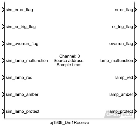
A J1939/73 DM1 message is a variable length message, transmitted by a network node to the global network address. The DM1 message contents detail any active diagnostic trouble codes and lamp status. As the message is variable in length, direct blockset support is provided (rather than relying on the pj1939_PgReceive block).
The application model may request the DM1 message or rely on the other J1939 node to transmit the DM1 message periodically. This block does not make a request for the DM1 message.
The simulation value for the outport rx_trig_flag.
Value type: Boolean Calibratable: No The simulation value for the outport error_flag.
Value type: Boolean Calibratable: No The simulation value for the outport overrun_flag.
Value type: Boolean Calibratable: No The simulation value for the outport lamp_malfunction.
Value type: Integer Calibratable: No The simulation value for the outport lamp_red.
Value type: Integer Calibratable: No The simulation value for the outport lamp_amber.
Value type: Integer Calibratable: No The simulation value for the outport lamp_protect.
Value type: Integer Calibratable: No The simulation value for the outport timestamp. Available only if the mask parameter Provide timestamp is selected.
Value type: Integer
Set to 1 if an error in receive processing relevant to this message has occurred.
Value type: Boolean Calibratable: No Set to 1 if a DM1 message matching the source address has been received since the last time the block was evaluated, 0 otherwise.
Value type: Boolean Calibratable: No Set to 1 if more than one DM1 messages matching the source address have been received since the last time the block was evaluated, 0 otherwise.
Value type: Boolean Calibratable: No The state value of the malfunction lamp.
Range: [0, 3] (0 is Slow Flash, 1 is Fast Flash, 2 is On, 3 is Off)
Value type: Integer Calibratable: No The state value of the red lamp.
Range: [0, 3] (0 is Slow Flash, 1 is Fast Flash, 2 is On, 3 is Off)
Value type: Integer Calibratable: No The state value of the amber lamp.
Range: [0, 3] (0 is Slow Flash, 1 is Fast Flash, 2 is On, 3 is Off)
Value type: Integer Calibratable: No The state value of the protect lamp.
Range: [0, 3] (0 is Slow Flash, 1 is Fast Flash, 2 is On, 3 is Off)
Value type: Integer Calibratable: No The time when the last valid message was received. Strictly this gives the time when the message was assembled from the possibly multiple CAN packets, and has a resolution of 50 ms. The timestamp is a free-running microsecond timer that wraps to zero approximately every 70 minutes. Available only if the mask parameter Provide timestamp is selected.
Range: [0, 4294967295] us
Value type: Integer
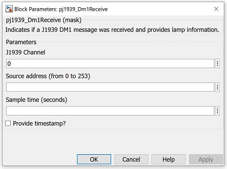
The logical J1939 channel on which the message will arrive. Must be a channel declared with a pj1939_ChannelConfiguration block.
Value type: Integer Calibratable: No The source J1939 network address of the message to be received.
Range: 0 or 253
Value type: Integer Calibratable: No The periodicity of the block execution.
Range: [0.001, 3600] seconds
Value type: Real Calibratable: No If selected then inport sim_timestamp and outport timestamp are made available.
Value type: Boolean Calibratable: No
Decodes the contents of the last received J1939-73 DM1 message based on specified DTC data.
None (Main library). (See Section 1.3, “Licensed Features”.)
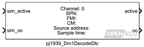
The active/not active status of a specified DTC as reported by another unit via J1939 DM1 messages can be monitored using this block. The outputs are updated each time a new DM1 message is received. Use the pj1939_Dm1Receive block to determine when a DM1 message is received.
Set to 1 if the DTC is active, 0 otherwise.
Value type: Boolean Calibratable: No The occurrence count of the DTC (as specified by the parameters Suspect parameter number, Failure mode indicator and Conversion method).
Range: [0, 127]
Value type: Integer Calibratable: No

The logical J1939 channel on which the message will arrive. Must be a channel declared with a pj1939_ChannelConfiguration block.
Value type: Integer Calibratable: No The value of the SPN for this DTC. The parameters Suspect parameter number, Failure mode indicator and Conversion method uniquely identify the DTC.
Range: [0, 524287]
Value type: Integer Calibratable: No The value of the FMI for this DTC. The parameters Suspect parameter number, Failure mode indicator and Conversion method uniquely identify the DTC.
Range: [0, 31]
Value type: Integer Calibratable: No The value of the CM for this DTC. The parameters Suspect parameter number, Failure mode indicator and Conversion method uniquely identify the DTC.
Range: 0 or 1
Value type: Integer Calibratable: No The source J1939 network address of the message.
Range: 0 or 253
Value type: Integer Calibratable: No The periodicity of the block execution.
Range: [0.001, 3600] seconds
Value type: Real Calibratable: No
Transmit a J1939-73 DM1 message containing the DTCs with an active state from a DTC table.
None (Main library). (See Section 1.3, “Licensed Features”.)
A J1939-73 DM1 message is a variable length message, transmitted by a network node to the global network address. The DM1 message contents detail any active diagnostic trouble codes. As the message is variable in length, direct blockset support is provided (rather than relying on the pj1939_PgTransmit block).
When the block iterates, the DTC table is inspected for active and previously active DTCs. If any differ since the last time the block iterated, a DM1 message could be sent. The J1939-73 specification explains how the periodic transmission of this message varies in relation to DTC activation state changes, as a need to limit J1939 network bandwidth.
Excerpt from J1939/73 specification, on transmission rate:
A DM1 message shall be transmitted, regardless of the presence or absence of any DTC, once every second and on state change. To prevent a high message rate due to intermittent faults that have a very high frequency, it is recommended that no more than one state change per DTC per second be transmitted. For example, if a fault has been active for 1 second or longer, and then becomes inactive, a DM1 message shall be transmitted to reflect this state change. If a different DTC changes state within the 1 second update period, a new DM1 message is transmitted to reflect this new DTC.
The simulation inport for the error_flag outport.
Value type: Boolean Calibratable: No Simulation value of the outport transport_errors.
Value type: Integer Calibratable: No Set to 1 to force the transmission of a DM1 message, set to zero otherwise.
Range: 0 or 1.
Value type: Boolean Calibratable: No J1939 priority of the DM1 message to be transmitted.
Range: [0, 7]
Value type: Integer Calibratable: No J1939 destination address for the DM1 message (This could be the source address of the corresponding PGN request, or the global address (255) if the request was sent to the global address). If use_dest_addr is false or a PDU2 message is shorter than 9 bytes, this value is ignored and the message is sent to the global address.
Range: [0, 255]
Value type: Integer Calibratable: No Whether to send the DM1 to a specified destination address. If false (0), the message will always be sent to the global address. Set to true (1) to allow the message to be sent to a specific destination address, such as the source address of a PGN request.
Range: 0 or 1.
Value type: Boolean Calibratable: No
Set to 1 when the DM1 message could not be buffered for transmission, or if a previous request to send a DM1 message has not completed.
Value type: Boolean Calibratable: No Saturated count of transport errors (timeout or aborts) for this message.
Range: [0, 255]
Value type: Integer Calibratable: No
The logical J1939 channel on which to transmit. Must be a channel declared with a pj1939_ChannelConfiguration block.
Value type: Integer Calibratable: No The name of the DTC table to act on (there must be a corresponding named table specified in a pdtc_Table block in the model).
Value type: String Calibratable: No
Indicates if a J1939-73 DM2 message has been received and decodes the contents of the lamp status.
None (Main library). (See Section 1.3, “Licensed Features”.)
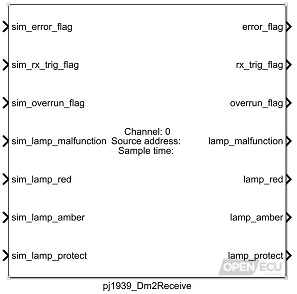
A J1939-73 DM2 message is a variable length message, transmitted by a network node to the global network address. The DM2 message contents detail any previously active diagnostic trouble codes and lamp statuses. As the message is variable in length, direct blockset support is provided (rather than relying on the pj1939_PgReceive block).
The application model must request the DM2 message. This block does not make a request for the DM2 message.
The simulation value for the outport error_flag.
Value type: Boolean Calibratable: No The simulation value for the outport rx_trig_flag.
Value type: Boolean Calibratable: No The simulation value for the outport overrun_flag.
Value type: Boolean Calibratable: No The simulation value for the outport lamp_malfunction.
Value type: Integer Calibratable: No The simulation value for the outport lamp_red.
Value type: Integer Calibratable: No The simulation value for the outport lamp_amber.
Value type: Integer Calibratable: No The simulation value for the outport lamp_protect.
Value type: Integer Calibratable: No The simulation value for the outport timestamp. Available only if the mask parameter Provide timestamp is selected.
Value type: Integer
Set to 1 if an error in receive processing relevant to this message has occurred.
Value type: Boolean Calibratable: No Set to 1 if a DM2 message matching the source address has been received since the last time the block was evaluated, 0 otherwise.
Value type: Boolean Calibratable: No Set to 1 if more than one DM2 messages matching the source address have been received since the last time the block was evaluated, 0 otherwise.
Value type: Boolean Calibratable: No The state value of the malfunction lamp.
Range: [0, 3] (0 is Slow Flash, 1 is Fast Flash, 2 is On, 3 is Off)
Value type: Integer Calibratable: No The state value of the red lamp.
Range: [0, 3] (0 is Slow Flash, 1 is Fast Flash, 2 is On, 3 is Off)
Value type: Integer Calibratable: No The state value of the amber lamp.
Range: [0, 3] (0 is Slow Flash, 1 is Fast Flash, 2 is On, 3 is Off)
Value type: Integer Calibratable: No The state value of the protect lamp.
Range: [0, 3] (0 is Slow Flash, 1 is Fast Flash, 2 is On, 3 is Off)
Value type: Integer Calibratable: No The time when the last valid message was received. Strictly this gives the time when the message was assembled from the possibly multiple CAN packets, and has a resolution of 50 ms. The timestamp is a free-running microsecond timer that wraps to zero approximately every 70 minutes. Available only if the mask parameter Provide timestamp is selected.
Range: [0, 4294967295] us
Value type: Integer
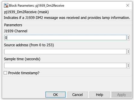
The logical J1939 channel on which the message will arrive. Must be a channel declared with a pj1939_ChannelConfiguration block.
Value type: Integer Calibratable: No The source J1939 network address of the message to be received.
Range: 0 or 253
Value type: Integer Calibratable: No The periodicity of the block execution.
Range: [0.001, 3600] seconds
Value type: Real Calibratable: No If selected then inport sim_timestamp and outport timestamp are made available.
Value type: Boolean Calibratable: No
Decodes the contents of the last received J1939-73 DM2 message based on specified DTC data.
None (Main library). (See Section 1.3, “Licensed Features”.)
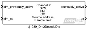
The previously active/not previously active status of a specified DTC as reported by another unit via J1939 DM2 messages can be monitored using this block. The outputs are updated each time a new DM2 message is received. Use the pj1939_Dm2Receive block to determine when a DM2 message is received.
The simulation value for the outport previously_active.
Value type: Boolean Calibratable: No The simulation value for the outport oc.
Value type: Integer Calibratable: No
Set to 1 if the DTC was previously active, 0 otherwise.
Value type: Boolean Calibratable: No The occurrence count of the DTC (as specified by the parameters Suspect parameter number, Failure mode indicator and Conversion method).
Range: [0, 127]
Value type: Integer Calibratable: No
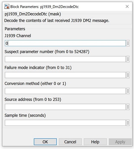
The logical J1939 channel on which the message will arrive. Must be a channel declared with a pj1939_ChannelConfiguration block.
Value type: Integer Calibratable: No The value of the SPN for this DTC. The parameters Suspect parameter number, Failure mode indicator and Conversion method uniquely identify the DTC.
Range: [0, 524287]
Value type: Integer Calibratable: No The value of the FMI for this DTC. The parameters Suspect parameter number, Failure mode indicator and Conversion method uniquely identify the DTC.
Range: [0, 31]
Value type: Integer Calibratable: No The value of the CM for this DTC. The parameters Suspect parameter number, Failure mode indicator and Conversion method uniquely identify the DTC.
Range: 0 or 1
Value type: Integer Calibratable: No The source J1939 network address of the message.
Range: 0 or 253
Value type: Integer Calibratable: No The periodicity of the block execution.
Range: [0.001, 3600] seconds
Value type: Real Calibratable: No
Transmit a J1939/73 DM2 message containing the DTCs with a previously active state from a DTC table.
None (Main library). (See Section 1.3, “Licensed Features”.)
A J1939/73 DM2 message is a variable length message, transmitted by a network node to the global network address. The DM2 message contents detail any previously active diagnostic trouble codes. As the message is variable in length, direct blockset support is provided (rather than relying on the pj1939_PgTransmit block).
The simulation inport for the error_flag outport.
Value type: Boolean Calibratable: No Simulation value of the outport transport_errors.
Value type: Integer Calibratable: No Set to 1 to transmit a DM2 message, set to zero otherwise.
Range: 0 or 1.
Value type: Boolean Calibratable: No J1939 priority of the DM2 message to be transmitted.
Range: [0, 7]
Value type: Integer Calibratable: No J1939 destination address for the DM2 message (This could be the source address of the corresponding PGN request, or the global address (255) if the request was sent to the global address). If use_dest_addr is false or a PDU2 message is shorter than 9 bytes, this value is ignored and the message is sent to the global address.
Range: [0, 255]
Value type: Integer Calibratable: No Whether to send the DM2 to a specified destination address. If false (0), the message will always be sent to the global address. Set to true (1) to allow the message to be sent to a specific destination address, such as the source address of a PGN request.
Range: 0 or 1.
Value type: Boolean Calibratable: No
Set to 1 when the DM2 message could not be buffered for transmission, or if a previous request to send a DM2 message has not completed.
Value type: Boolean Calibratable: No Saturated count of transport errors (timeout or aborts) for this message.
Range: [0, 255]
Value type: Integer Calibratable: No
The logical J1939 channel on which to transmit. Must be a channel declared with a pj1939_ChannelConfiguration block.
Value type: Integer Calibratable: No The name of the DTC table to act on (there must be a corresponding named table specified in a pdtc_Table block in the model).
Value type: String Calibratable: No
Extract the data contents from a received J1939 message.
None (Main library). (See Section 1.3, “Licensed Features”.)
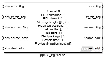
When a matching J1939 message to this block is received, the block unpacks the message contents into individual signals, as specified by the block mask parameters, and provides them as outports.
Warning
The PCX feature takes precedence over the PJ1939 feature. If you configure the PCX feature to receive a J1939 frame, the PJ1939 feature will not see the frame, and it will not be processed by the platform. This especially causes problems when receiving J1939 DM14 'Boot Load' commands.
Simulation value for the outport error_flag.
Value type: Boolean Calibratable: No Simulation value for the outport rx_trig_flag.
Value type: Boolean Calibratable: No Simulation value for the outport overrun_flag.
Value type: Boolean Calibratable: No Simulation value for the outport source_addr.
Value type: Integer Calibratable: No Simulation value for the outport dest_addr.
Value type: Integer Calibratable: No The simulation value for the outport timestamp. Available only if the mask parameter Provide timestamp is selected.
Value type: Integer A set of simulation inports for the corresponding outports fields. Available if there is at least one field and the parameter Provide simulation input? is selected.
Value type: Integer Calibratable: No
Set to 1 if some error has occurred which prevents CAN reception, or 0 otherwise. Errors which prevent reception are: CAN bus detected as bus-off, or the length of the received J1939 message does not match the Message length parameter.
Range: 0 or 1
Value type: Boolean Calibratable: No Set to 1 if the block has detected reception of the J1939 message since the last iteration of this block, set to zero otherwise.
Range: 0 or 1
Value type: Boolean Calibratable: No Set to 1 if the block has detected reception of the same J1939 message more than once between iterations of this block.
Range: 0 or 1
Value type: Boolean Calibratable: No The source J1939 network address of the message.
Range: [0, 253] or 255
Value type: Integer Calibratable: No The destination J1939 network address of the message.
Range: [0, 253] or 255
Value type: Integer Calibratable: No The time when the last valid message was received. Strictly this gives the time when the message was assembled from the possibly multiple CAN packets, and has a resolution of 50 ms. The timestamp is a free-running microsecond timer that wraps to zero approximately every 70 minutes. Available only if the mask parameter Provide timestamp is selected.
Range: [0, 4294967295] us
Value type: Integer An outport for each field specified in the block.
Value type: Real Calibratable: No
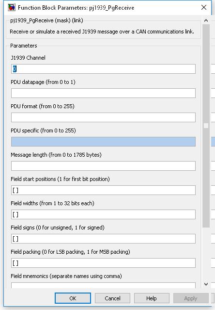
The logical J1939 channel on which the message will arrive. Must be a channel declared with a pj1939_ChannelConfiguration block.
Value type: Integer Calibratable: No The pdu datapage value of the PGN of the J1939 message to receive.
Range: 0 or 1
Value type: Integer Calibratable: No The pdu format value of the PGN of the J1939 message to receive.
Range: [0, 255]
Value type: Integer Calibratable: No The pdu specific value of the PGN of the J1939 message to receive. If the PDU format parameter is less than 240, then this parameter is not available for editing and does not form part of the PGN.
Range: [0, 255]
Value type: Integer Calibratable: No The length of the data bytes in the message to be received.
Range: [0, 1785]
Value type: Integer Calibratable: No A vector of bit numbers indicating the start position of each field in the CAN message.
Field start positions correspond to the message data bytes as follows:
Data byte Bit number LS MS LS 1 8 7 6 5 4 3 2 1 2 16 15 14 13 12 11 10 9 ... ... 1785 14280 14279 14278 14277 14276 14275 14274 14273 MS MS LS where byte 1 corresponds to the first received data byte in the first CAN message for the J1939 message. This numbering scheme matches the J1939 specification but differs from the existing CAN blocks. Although this may cause some confusion when both blocks are used in the same model, it will help reduce mistakes when using the J1939 blockset with the J1939 specification of message contents.
Value type: Integer Calibratable: No A vector of bit lengths indicating the number of bits allocated to each field.
Range: [1, 32] bits
A field which starts at bit 5 and has 10 bits of width is identified as follows:
Data byte Bit number 1 8 7 6 5 - - - - 2 - - 14 13 12 11 10 9 Value type: Integer Calibratable: No A vector of zero or one values, corresponding to each field. Fields for which this is set 1 are received as twos-complement signed numbers, or unsigned numbers otherwise.
Range: 0 or 1
Value type: Integer Calibratable: No A vector of zero or one values, corresponding to each field. Fields for which this is set 1 are received as MS packing, or LS packing otherwise.
Range: 0 or 1
J1939 message fields are generally packed LS byte first, so the field which starts at bit 5 and has 10 bits of width, would be interpreted as:
MS LS Data byte 2 Data byte 1 - - - - - - 14 13 12 11 10 9 8 7 6 5 s s s s s s x x x x x x x x x x where 'x' is the corresponding bit taken from the J1939 message data bytes, and 's' is the sign extension of the data. In this case, bit 14 may be considered the sign bit, if the data in the J1939 message data is signed.
However, if the J1939 message field was packed MS byte first, the bits would be interpreted as:
MS LS Data byte 1 Data byte 2 - - - - - - 6 5 14 13 12 11 10 9 8 7 s s s s s s x x x x x x x x x x where 'x' is the corresponding bit taken from the J1939 message data bytes, and 's' is the sign extension of the data. In this case, bit 6 may be considered the sign bit, if the data in the J1939 message data is signed.
Value type: Integer Calibratable: No A string containing a comma-separated list of names with which to label the simulation field inports and message field outports.
Range: 0 or 1
Value type: String Calibratable: No If selected then create simulation inports (sim_fields) for each of the outport message signals (fields).
Value type: Boolean Calibratable: No If selected then inport sim_timestamp and outport timestamp are made available.
Value type: Boolean Calibratable: No The periodicity of the block execution.
Range: [0.001, 3600] seconds
Value type: Real Calibratable: No
Unused fields in a J1939 message need not be specified in the Field start positions parameter.
If the block shows unnamed outports, or if the field outports are not shown, it is likely that one or more of the block's parameter fields is incorrect. Check the parameter fields for mistakes and correct them.
The following example illustrates the least significant (LS) and most significant (MS) byte ordering in J1939 messages. The message is received as follows:
MS LS Byte 1 2 3 4 5 6 Message (hex) 11 10 FF FF 20 21 where the first parameter is in LS byte format, starts at bit 0, is 16 bits wide and unsigned, and the second parameter is in MS byte format, starts at bit 32, and is also 16 bit wide and unsigned.
Parameter 1 is unpacked using LS byte formatting giving 0x1011. The LS byte is unpacked from the LS byte of its position within the message (byte 1) giving 0x11, and the MS byte is unpacked from the MS byte of its position within the message (byte 2) giving 0x10.
Parameter 2 is unpacked using MS byte formatting giving 0x2021. The LS byte is unpacked from the MS byte of its position within the message (byte 6) giving 0x21, and the MS byte is unpacked from the MS byte of its position within the message (byte 5) giving 0x20.
Determine whether a Parameter Group (PG) has been requested by another J1939 network node.
None (Main library). (See Section 1.3, “Licensed Features”.)
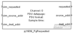
The pj1939_PgRequested block captures all J1939/21 Request PGN messages directed at the ECU and determines if the model must respond to any of them. If the model is configured to do so (by use of this block), then the model must implement an appropriate action or response. If the model is not configured to do so, then the ECU will respond with a NACK (if it is appropriate to do so).
The PGN to match against any J1939 request message, is specified by parameters PDU datapage, PDU format and PDU specific. If a matching PGN has been requested, then the outport requested is set to 1. The PGN must not be duplicated in more than one pj1939_PgRequest block.
Requests for DM1, DM2, DM3, DM4, DM5, DM6, DM11, DM12, DM20, DM21, DM23, DM24, DM25, DM26, DM27, DM28, DM29, DM31, DM32, DM34, DM41, DM42, DM43, DM44, DM45, DM46, DM47, DM48, DM49, DM50, DM51 and DM52 messages are handled by the model using this block. The application modeller must then provide the necessary logic to handle the request using the corresponding pdtc_ClearAllIfActive, pdtc_ClearAllIfInactive, pj1939_Dm1Transmit, pj1939_Dm2Transmit, pj1939_Dm4Transmit, pj1939_Dm5Transmit, pj1939_Dm8Transmit, pj1939_Dm10Transmit, pj1939_Dm20Transmit, pj1939_Dm21Transmit, pj1939_Dm24Transmit, pj1939_Dm25Transmit, pj1939_Dm26Transmit, pj1939_Dm30Transmit, pj1939_Dm32Transmit, pj1939_Dm34Transmit, and pj1939_TransmitDtcDm blocks.
Simulation value for the inport requested.
Value type: Boolean Calibratable: No Simulation value for the inport source_addr.
Value type: Integer Calibratable: No Simulation value for the inport dest_addr. Available only if the parameter PDU format is less than 240.
Value type: Integer Calibratable: No The simulation value for the outport timestamp. Available only if the mask parameter Provide timestamp is selected.
Value type: Integer
Set to 1 if the pgn defined by the parameters PDU datapage, PDU format and PDU specific matches a request message.
Range: 0 or 1
Value type: Boolean Calibratable: No The source J1939 network address of the request message.
Range: [0, 253] or 255
Value type: Integer Calibratable: No The destination J1939 network address of the request message. Available only if the parameter PDU format is less than 240.
Range: [0, 253] or 255
Value type: Integer Calibratable: No The time when the last valid message was received. Strictly this gives the time when the message was assembled from the possibly multiple CAN packets, and has a resolution of 50 ms. The timestamp is a free-running microsecond timer that wraps to zero approximately every 70 minutes. Available only if the mask parameter Provide timestamp is selected.
Range: [0, 4294967295] us
Value type: Integer
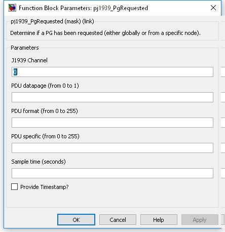
The logical J1939 channel on which the request will arrive. Must be a channel declared with a pj1939_ChannelConfiguration block.
Value type: Integer Calibratable: No The pdu datapage value of the PGN to match against a J1939 request message.
Range: 0 or 1
Value type: Integer Calibratable: No The pdu format value of the PGN to match against a J1939 request message.
Range: [0, 255]
Value type: Integer Calibratable: No The pdu specific value of the PGN to match against a J1939 request message. If the PDU format parameter is less than 240, then this parameter is not available for editing and does not form part of the PGN.
Range: [0, 255]
Value type: Integer Calibratable: No The periodicity of the block execution.
Range: [0.001, 3600] seconds
Value type: Real Calibratable: No If selected then inport sim_timestamp and outport timestamp are made available.
Value type: Boolean Calibratable: No
Construct the contents of a J1939 message, and attempt to transmit it.
None (Main library). (See Section 1.3, “Licensed Features”.)
When a J1939 message is to be transmitted, the block packs each of the signal inports into the message, as specified by the block mask parameters, and transmits the message.
Simulation value of the outport error_flag.
Value type: Boolean Calibratable: No Simulation value of the outport transport_errors.
Value type: Integer Calibratable: No The priority of the J1939 message to transmit.
Range: [0, 7]
Value type: Integer Calibratable: No
The logical J1939 channel on which to transmit. Must be a channel declared with a pj1939_ChannelConfiguration block.
Value type: Integer Calibratable: No The pdu datapage value of the PGN of the J1939 message to transmit.
Range: 0 or 1
Value type: Integer Calibratable: No The pdu format value of the PGN of the J1939 message to transmit.
Range: [0, 255]
Value type: Integer Calibratable: No The pdu specific value of the PGN of the J1939 message to transmit. If the PDU format parameter is less than 240, then this parameter is not available for editing and does not form part of the PGN.
Range: [0, 255]
Value type: Integer Calibratable: No The length of the data bytes in the message to transmit. Maximum size is the smaller of maximum range or buffer size.
Range: [0, 1785]
Value type: Integer Calibratable: No A vector of bit numbers indicating the start position of each field in the CAN message.
Field start positions correspond to the message data bytes as follows:
Data byte Bit number LS MS LS 1 8 7 6 5 4 3 2 1 2 16 15 14 13 12 11 10 9 ... ... 1785 14279 14278 14277 14276 14275 14274 14273 14272 MS MS LS where byte 1 corresponds to the first received data byte in the first CAN message for the J1939 message. This numbering scheme matches the J1939 specification but differs from the existing CAN blocks. Although this may cause some confusion when both blocks are used in the same model, it will help reduce mistakes when using the J1939 blockset with the J1939 specification of message contents.
Value type: Integer Calibratable: No A vector of bit lengths indicating the number of bits allocated to each field.
Range: [1, 32] bits
A field which starts at bit 5 and has 10 bits of width is identified as follows:
Data byte Bit number 1 8 7 6 5 - - - - 2 - - 14 13 12 11 10 9 Value type: Integer Calibratable: No A vector of zero or one values, corresponding to each field. Fields for which this is set 1 are transmitted as MS packing, or LS packing otherwise.
Range: 0 or 1
J1939 message fields are generally packed LS byte first, so the field which starts at bit 5 and has 10 bits of width, would be interpreted as:
MS LS Data byte 2 Data byte 1 - - - - - - 14 13 12 11 10 9 8 7 6 5 s s s s s s x x x x x x x x x x where 'x' is the corresponding bit taken from the J1939 message data bytes, and 's' is the sign extension of the data. In this case, bit 14 may be considered the sign bit, if the data in the J1939 message data is signed.
However, if the J1939 message field was packed MS byte first, the bits would be interpreted as:
MS LS Data byte 1 Data byte 2 - - - - - - 6 5 14 13 12 11 10 9 8 7 s s s s s s x x x x x x x x x x where 'x' is the corresponding bit taken from the J1939 message data bytes, and 's' is the sign extension of the data. In this case, bit 6 may be considered the sign bit, if the data in the J1939 message data is signed.
Value type: Integer Calibratable: No A string containing a comma-separated list of names with which to label the message field inports.
Range: 0 or 1
Value type: String Calibratable: No
Unused fields in a J1939 message need not be specified in the Field start positions parameter (bits in unused fields are set to 1 for transmission).
If the block shows unnamed inports, or if the field inports are not shown, it is likely that one or more of the block's parameter fields is incorrect. Check the parameter fields for mistakes and correct them.
The following example illustrates the least significant (LS) and most significant (MS) byte ordering in J1939 messages. Given two parameters:
MS LS Byte 1 2 Parameter 1 (hex) 10 11 Parameter 2 (hex) 20 21 the first parameter is packed into the J1939 message in LS byte format, starting at bit 0, is 16 bits wide and unsigned, and the second parameter is packed in MS byte format, starting at bit 32, and is also 16 bit wide and unsigned.
MS LS Byte 1 2 3 4 5 6 Message (hex) 11 10 FF FF 20 21 Parameter 1 has been packed using LS byte formatting. The LS byte of 0x1011 (0x11) has been packed into the LS byte of its position within the message (byte 1), and the MS byte of 0x1011 (0x10) has been packed into the MS byte of its position within the message (byte 2).
Parameter 2 is packed using MS byte formatting. The LS byte of 0x2021 (0x21) has been packed into the MS byte of its position within the message (byte 6), and the MS byte of 0x2021 (0x20) has been packed into the MS byte of its position within the message (byte 5).
Bytes 2 and 3 are not used and are therefore set with all bits at 1.
Specify or append linker options when building a model.
None (Main library). (See Section 1.3, “Licensed Features”.)
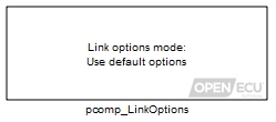
After RTW has generated code for a model, a compiler converts the code into a binary image suitable for the ECU to execute. Which compiler to use is chosen through the RTW Compiler Selection option.
The compiler's linker combines each of the compiled source code files into a binary image using various transformations, some of which can be modified via command line options to the compiler. The pcomp_LinkOptions block selects whether to use the default linker options supplied with OpenECU, to add additional options to the default options, or to replace the default options altogether.
Warning
Alteration of the linker options may lead to a model which will not build, or a model which will not run on the target ECU or which may run initially but fail later on. When reporting a failure through technical support, please specify any changed linker options as this may help resolve the issue more quickly.
- All Diab compilers
The default linker options for all WindRiver Diab compilers are:
Option Use -f65535fill unused memory regions with set bits — this mirrors the functionality of some post-processing build scripts -lcask the linker to include part of the standard C library -lmask the linker to include the math part of the standard C library -m2ask the linker to produce a map file with a particular layout — essential for some post-processing of the build files -t...set to -tPPCE200Z3VEFfor the M220, M221, M250, M460 and M461 or set to-tPPCE200Z7VEFfor the M670 — selects the processor for the target ECU-Xcheck-overlappingask the linker to check that memory regions and data within those regions, do not overlap -Xelfask the linker to generate an ELF object file format — essential for some post-processing of the build files
- GCC 4.7.3 Compiler
The default linker options for the GCC compiler are:
Option Use -Mprint a link map to the standard output -lgccask the linker to try and link against libgcc.a -lcask the linker to include part of the standard C library -lmask the linker to include the math part of the standard C library --check-sectionsask the linker to check section addresses after they have been assigned to see if there are any overlaps --emit-stub-symslabel linker stubs with a local symbol that encodes the stub type and destination -crefoutput a cross reference table. If a linker map file is being generated, the cross reference table is printed to the map file. Otherwise, it is printed on the standard output -m elf32ppcemulate the elf32ppc linker
Note
Its outside the scope of this User Guide to explain all the different linker options in detail and their resulting affect on the ECU binary image. Please refer to appropriate compiler User Guide for more information.
Note
Alteration of the linker options may remove options which work around known bugs in the compiler. For a list of known bugs which affect OpenECU, see Section 2.5.9.2, “Known defects”, Section 2.5.10.2, “Known defects”, Section 2.5.11.2, “Known defects” and Section 2.5.12.2, “Known defects”.
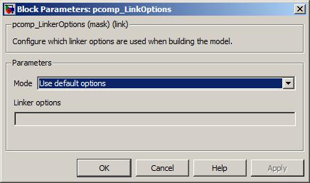
Whether to use the default linker options, whether to add linker options to the default options, or whether to replace the default options altogether.
Value type: List Calibratable: No The options to add to the default linker options, or to replace the default options, as selected by parameter Mode.
Value type: String Calibratable: No
Configure the memory allocation.
None (Main library). (See Section 1.3, “Licensed Features”.)
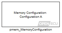
Various configurations are available for dividing the available volatile and non-volatile memory between use for code, calibration and general RAM.
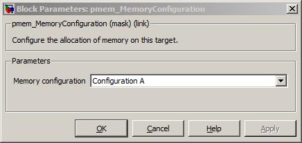
A list of the memory configurations available for this target. See Memory configurations for details of the memory configurations available for different targets.
Value type: List Calibratable: No
The model identification block specifies which ECU hardware to target and information to be recorded in the built model and calibration image.
None (Main library). (See Section 1.3, “Licensed Features”.)
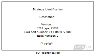
The model identification block is usually placed in the top level Simulink diagram of the model. It contains a mask entry which can be used to display a description of the model.
The model identification block also specifies the following information which is recorded in the built calibration image:
model version numbers (major, minor and sub-minor);
copyright description.
In the case of the copyright description, the information is placed in the model image and the calibration image.
The model identification block also selects the target hardware the model will expect to run on. This parameter should be selected when the model is first created. Changing the parameter later on has consequences (see the Notes section for the put_Identification block for more details).
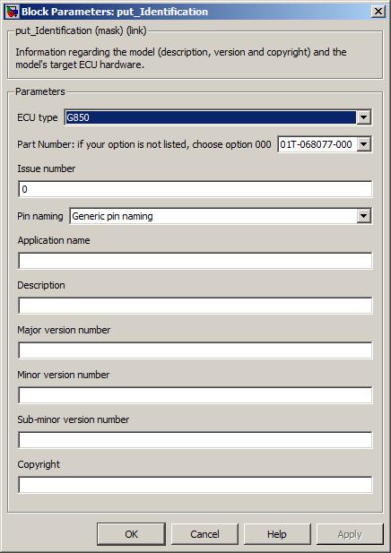
Specifies the name of the ECU that the model will run on. Selection of the ECU type changes the possible inputs and outputs on other blocks. The parameter should be selected at the start of the model but if it must be changed later (for instance, moving to another hardware platform to reduce costs) then consult the Notes section for the put_Identification block for more details.
Value type: List Calibratable: No Specifies the hardware part number that appears on the ECU casing, followed by a hyphen and a three-character suffix. This suffix denotes the option. Only those options that require special software support are explicitly listed. If the option is not explicitly listed, then option 000 should be selected.
Value type: List Calibratable: No Specifies the issue or revision number of the ECU that the model will run on. This is the first number that appears after the hardware part number on the label of the ECU. For example, if "2m4" appears after the hardware part number, then the issue number to be entered is 2.
Value type: Integer Calibratable: No Specifies the type of names used for pin and channel identification. Generic pin naming uses the following terms for each pin.
Table 6.4. Generic pin naming convention
Name Description AIN Analogue input AOT Analogue output DIN Digital input DOT Digital output Monitor Feedback signal from output driver circuitry
Powertrain pin naming uses a scheme that shortens the typical application naming given in the target specification tables linked to in Section A.1, “ECU hardware reference documentation”. The default selection for this drop-down is Powertrain pin naming to maintain backwards compatibility with existing models.
Value type: List Calibratable: No Specifies the name of the model/application. The name has no functional effect on the model but is used when generating ASAP2 files and in response to the CCP EXCHANGE-ID message.
The name can include tokens which are automatically converted during model build. Tokens are single words starting and ending in the “
%” character. For instance, the string “Application for %target%” contains one token named target, which is converted to the target ECU name during a model build. The following table lists the available tokens:Token Replacement %copyright%Replaced with the string from the Copyright parameter. %target%Replaced with a string representing the ECU target and option. %ver-major%Replaced with the string from the Major version number parameter. %ver-minor%Replaced with the string from the Minor version number parameter. %ver-subminor%Replaced with the string from the Sub-minor version number parameter. The name can be read from the target at run time by displaying the
mpls_app_nameautomatic ASAP2 entry.Value type: String Calibratable: No Specifies a description of the model. The description is displayed in the block. This has no functional effect on the model. The description can be read from the target at run time by displaying the
mpls_app_descriptionautomatic ASAP2 entry.Value type: String Calibratable: No Specifies the major version number of the model. This has no functional effect on the model. The version can be read from the target at run time by displaying the
mpl_app_ver_majorautomatic ASAP2 entry.Range: [0, 255]
Value type: Integer Calibratable: No Specifies the major version number of the model. This has no functional effect on the model. The version can be read from the target at run time by displaying the
mpl_app_ver_minorautomatic ASAP2 entry.Range: [0, 255]
Value type: Integer Calibratable: No Specifies the major version number of the model. This has no functional effect on the model. The version can be read from the target at run time by displaying the
mpl_app_ver_subminorautomatic ASAP2 entry.Range: [0, 255]
Value type: Integer Calibratable: No Specifies a copyright string that is embedded in the generated image. This has no functional effect on the model. The copyright can be read from the target at run time by displaying the
mpls_app_copyrightautomatic ASAP2 entry.Value type: String Calibratable: No
The Description parameter text can usually be split into multiple lines to make it more readable. As the edit box of the description provides for a single line only, a new line can be inserted by added the characters
\nwhere a new line is required.Changing the ECU type parameter affects which inputs and outputs are selectable in other blocks. This is also a risk when changing the parameters Part Number and Issue Number. If a model contains such blocks, then when the target hardware is changed, the inputs and outputs change when the model is next loaded or when a block is updated. If a change in hardware is necessary, then the user should work out how the inputs and outputs will change between hardware targets, then open the model, change the hardware selection, save and close the model, then reload the model and modify each block input or output appropriately.
Accidental changes to the hardware target may leave the block inputs and outputs in an undefined state.
Store adaptive data.
None (Main library). (See Section 1.3, “Licensed Features”.)
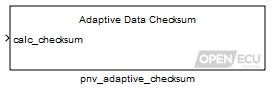
Adaptive data can be modified from the default values of scalar, 1-d or 2-d maps, or arrays while the model is running, and recalled next time the model is started. The method depends on the ECU and its configuration options:
In most ECUs, adaptive data is stored in flash. This is retained when the ECU is unpowered.
In either case, a checksum is used to validate the data at start-up time. If the checksums match at start-up, the adaptive data is retained from the previous power cycle, otherwise the adaptive data is reverted to default. In most ECUs, the data is also reverted to default if the stored data size or application version number are incompatible with the current build of software.
This block is used to force the stored data to be updated. When the inport calc_checksum transitions from 0 to 1, the block pauses execution of the model, calculates the checksum and stores the adaptive data, then continues execution of the model. In the case of battery-backed RAM, that merely involves computing the new checksum, but in the case of flash the memory is physically reprogrammed. Real-time execution will be briefly affected.
If using battery-backed storage, it is important to trigger the adaptive checksum update and not update adaptive data thereafter before shutting down the ECU. If adaptive data is modified after the checksum has been updated, and the ECU shuts down, next time it powers up, adaptive data will revert to default. (For flash, it will revert to the last saved data.)
To ensure the battery-backed checksum is up to date before shutting down the ECU, the pnv_Status block provides an indication of whether the checksum is correct or not. If not, shutdown of the module can be prevented (if conditions are appropriate) and the checksum updated. That block also indicates if the last flash save was successful.
Note
Flash memory wears out over time, and after a minimum number of checksum updates, the Flash memory is more likely to forget information each time the checksum is updated. For this reason, Flash is only programmed when adaptive data has changed since the last checksum update (either through an adaption operation or reset operation).
See the technical specification for each ECU for information about the Flash capabilities of each ECU.
Old adaptive data is reused so long as it has the expected total data size and was written by an application with the same user-specified version number. Otherwise the values revert to defaults. If the usage of adaptive blocks has changed in a new software version, increase the application sub-minor version number to ensure that any old values are not used, as they may not map appropriately to the blocks in the new model even if the total data size happens to match.
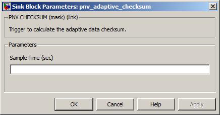
Adaptive 1-d map look-up and interpolation.
None (Main library). (See Section 1.3, “Licensed Features”.)
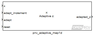
Looks up the inport x in the X-axis Data (default) parameter, interpolates the corresponding elements in the Adaptive Z Data (default) parameter, giving a corresponding adapted_z as the output.
The adaptive 1-d look-up block is similar to the OpenECU put_Calmap1d block, except that the z-axis look-up values can change over time under control of the model and be recovered from non-volatile memory when the model starts. If the adaptive values cannot be recovered at start-up, or if the model is simulated, the default values are used before any adaption takes place.
The target non-volatile memory is provided in two ways: either through storage that requires an external power source when the ECU is powered down (battery backed RAM storage), or not (Flash storage). See the technical specification for details on which storage type is supported by each target.
The battery backed non-volatile memory requires a small amount of power overall, i.e., much less than powering the ECU normally.
The adaptive data is check-summed using a 16-bit CRC. Failure to match the check-sum against the adaptive data on start-up means that the data cannot be recovered. In this case, or if the model is simulated, adaptive data is reverted to the default value specified when the model was built.
Warning
Unlike R12 Simulink maps, 1-d and 2-d maps in OpenECU do not extrapolate beyond the limits of the input axis or axes. OpenECU calibration maps should be used for all maps that form part of an OpenECU build.
Some calibration tools provide a feature which shows the map in graphical or tabular
form together with the active interpolation point. OpenECU supports this feature by populating
the ASAP2 file with the signal name which corresponds to the x inport.
To make this feature work, the x signal must be a named DD entity with its
storage class property set to ExportedGlobal.
The x-value at which a z-value is to be adapted then interpolated. May be a scalar or a vector. If the inport is attached to a vector, the size of the vector must match the size of any vector attached to another inport.
Value type: Real Calibratable: No The increment to the current adapted value. The increment is only used when the inports adapt and reset are conditioned correctly. May be a scalar or a vector. If the inport is attached to a vector, the size of the vector must match the size of any vector attached to another inport.
Value type: Real Calibratable: No 1 if the current adapted value should be adjusted, 0 otherwise. If the inport reset is 1, no adaption will occur (even if inport adapt is 1). May be a scalar or a vector. If the inport is attached to a vector, the size of the vector must match the size of any vector attached to another inport.
Range: 0 or 1
Value type: Boolean Calibratable: No 1 if the current adapted value should be reset to Adaptive Z Data (default), 0 otherwise. May be a scalar or a vector. If the inport is attached to a vector, the size of the vector must match the size of any vector attached to another inport.
Range: 0 or 1
Value type: Boolean Calibratable: No
The adapted value or values interpolated from parameter Adaptive Z Data (default) at the value or values for inport x.
Value type: Real Calibratable: No
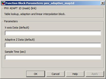
The name of the map's x axis (e.g.
vftm_mymap_x, see Section "Naming rules"). There must be two or more elements in this parameter and that must be the same as the number of elements in parameter Adaptive Z Data (default). The values of this parameter must increase monotonically and adjacent values must not be the same.Value type: Real Calibratable: Yes, offline and online The name of the map's z axis (e.g.
vftm_mymap_zsee Section "Naming rules"). There must be two or more elements in this parameter and that must be the same as the number of elements in X-axis Data (default). The adaptive block reverts to these values when the reset inport is asserted or when the block data is unrecoverable during power initialisation of the ECU.Value type: Real Calibratable: Yes, offline and online The periodicity of the block execution.
Range: [0.001, 3600] seconds
Value type: Real Calibratable: No
The build process generates a corresponding ASAP2 entry to the adaptive parameter that can be accessed via a calibration tool. The name of this entry has a fifth character 'a', i.e., given the default parameter name
vtfm_mymap_z, an ASAP2 entry with namevtfma_mymap_zis generated. Note that this implies that only a single adaptive parameter can exist per named default parameter.Warning
If two or more blocks refer to the same named item in the Adaptive Z Data (default) field, these blocks will independently adapt the same adaptive parameter.
The reset, adaption, look-up and interpolation work as follows:
Possible reset
If the inport reset is 1, the block reverts the Adaptive Z Data (default) parameter data to the block's defaults and sets the output from a look-up and interpolation.
Possible adaption
If a reset has not occurred and the inport adapt is 1, then the Adaptive Z Data (default) parameter data is altered as follows before setting the output from a look-up and interpolation.
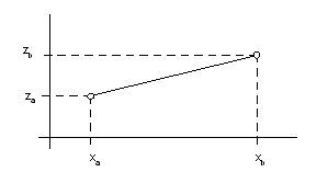
xa and xb bound inport x (see exceptions below), za and zb are the corresponding elements of the parameter Adaptive Z Data (default).
When the software adapts the 1-d look-up table, the Adaptive Z Data (default) is modified as follows:
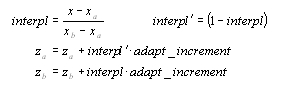
If the inport x is less than xa and xa is the first element in the X-axis Data (default) parameter then the software treats xb as the same element as xa, zb as the same element as za and performs the adaption calculation with interpl as 0.
If the inport x is greater than xb and xb is the last element in the X-axis Data (default) parameter then the software treats xa as the same element as xb, za as the same element as zb and performs the adaption calculations with interpl as 1.
Look-up and interpolation
Works as the put_Calmap1d block.
Adaptive 2-d map look-up and interpolation.
None (Main library). (See Section 1.3, “Licensed Features”.)
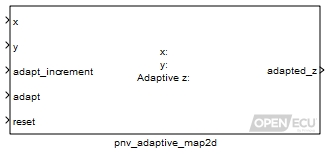
Looks up the input x and y in the X-axis Data (default) and Y-axis Data (default) parameters, interpolates between the corresponding Adaptive Z Data (default) parameter elements, giving a corresponding adapted_z as output.
The adaptive 2-d look-up block is similar to the OpenECU put_Calmap2d block, except that the z-axis look-up values can change over time under control of the model and be recovered from non-volatile memory when the model starts. If the adaptive values cannot be recovered at start-up, or if the model is simulated, the default values are used before any adaption takes place.
The target non-volatile memory is provided in two ways: either through storage that requires an external power source when the ECU is powered down (battery backed RAM storage), or not (Flash storage). See the technical specification for details on which storage type is supported by each target.
The battery backed non-volatile memory requires a small amount of power overall, i.e., much less than powering the ECU normally.
The adaptive data is check-summed using a 16-bit CRC. Failure to match the check-sums on start-up means that the data cannot be recovered. In this case, or if the model is simulated, adaptive data is reverted to the default value specified when the model was built.
Warning
Unlike R12 Simulink maps, 1-d and 2-d maps in OpenECU do not extrapolate beyond the limits of the input axis or axes. OpenECU calibration maps should be used for all maps that form part of an OpenECU build.
Some calibration tools provide a feature which shows the map in graphical or tabular
form together with the active interpolation point. OpenECU supports this feature by populating
the ASAP2 file with the signal names which correspond to the x and y inports.
To make this feature work, the x and y signals must be named DD entities with their
properties set to ExportedGlobal.
The x-value at which a z-value is to be adapted then interpolated. May be a scalar or a vector. If the inport is attached to a vector, the size of the vector must match the size of any vector attached to another inport.
Value type: Real Calibratable: No The y-value at which a z-value is to be adapted then interpolated. May be a scalar or a vector. If the inport is attached to a vector, the size of the vector must match the size of any vector attached to another inport.
Value type: Real Calibratable: No The increment to the current adapted value. The increment is only used when the inports adapt and reset are conditioned correctly. May be a scalar or a vector. If the inport is attached to a vector, the size of the vector must match the size of any vector attached to another inport.
Value type: Real Calibratable: No 1 if the current adapted value should be adjusted, 0 otherwise. If the inport reset is 1, no adaption will occur (even if inport adapt is 1). May be a scalar or a vector. If the inport is attached to a vector, the size of the vector must match the size of any vector attached to another inport.
Range: 0 or 1
Value type: Boolean Calibratable: No 1 if the current adapted value should be forced to Adaptive Z Data (default), 0 otherwise. May be a scalar or a vector. If the inport is attached to a vector, the size of the vector must match the size of any vector attached to another inport.
Range: 0 or 1
Value type: Boolean Calibratable: No
The adapted value or values interpolated from parameter Adaptive Z Data (default) at the values for inports x and y.
Value type: Real Calibratable: No
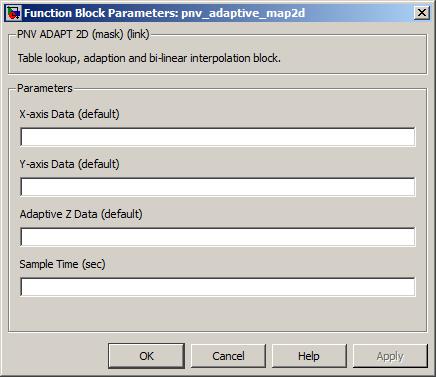
The name of the map's x axis (e.g.
vftm_mymap_x, see Section "Naming rules"). There must be two or more elements in this parameter and that must be the same as the number of elements as columns in parameter Adaptive Z Data (default). The values of this parameter must increase monotonically and adjacent values must not be the same.Value type: Real Calibratable: No The name of the map's y axis (e.g.
vftm_mymap_y, see Section "Naming rules"). There must be two or more elements in this parameter and that must be the same as the number of elements as rows in parameter Adaptive Z Data (default). The values of this parameter must increase monotonically and adjacent values must not be the same.Value type: Real Calibratable: No The name of the map's z matrix (e.g.
vftm_mymap_z, see Section "Naming rules"). There must be the same number of rows as elements in parameter Y-axis Data (default) and number of columns as elements in parameter X-axis Data (default).Value type: Real Calibratable: No The periodicity of the block execution.
Range: [0.001, 3600] seconds
Value type: Real Calibratable: No
The build process generates a corresponding ASAP2 entry to the adaptive parameter that can be accessed via a calibration tool. The name of this entry has a fifth character 'a', i.e., given the default parameter name
vtfm_mymap_z, an ASAP2 entry with namevtfma_mymap_zis generated. Note that this implies that only a single adaptive parameter can exist per named default parameter.Warning
If two or more blocks refer to the same named item in the Adaptive Z Data (default) field, these blocks will independently adapt the same adaptive parameter.
The reset, adaption, look-up and interpolation work as follows:
Possible reset
If the inport reset is 1, the block reverts the Adaptive Z Data (default) parameter data to the block's defaults and sets the output from a look-up and interpolation.
Possible adaption
If a reset has not occurred and the inport adapt is 1, then the Adaptive Z Data (default) parameter data is altered as follows before setting the output from a look-up and interpolation.
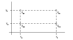
xa and xb bound
x(see exceptions below), ya and yb boundy(see exceptions below), zaa , zab, zba and zbb are the corresponding elements in the parameter Adaptive Z Data (default).When the software adapts the 2-d look-up table, the Adaptive Z Data (default) is modified as follows:
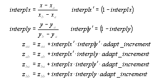
If the inport x is less than xa and xa is the first element in the X-axis Data (default) parameter then the software shall treat xb as the same element as xa, zab as the same element as zaa and perform the adaption calculation with interplx as 0.
If the inport x is greater than xb and xb is the last element in the X-axis Data (default) parameter then the software shall treat xa as the same element as xb, zaa as the same element as zab and perform the adaption calculation with interplx as 1.
Similar restrictions apply for the y inport.
Look-up and interpolation
Works as the put_Calmap1d block.
Non-volatile adaptive scalar block.
None (Main library). (See Section 1.3, “Licensed Features”.)
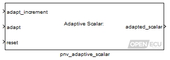
The adaptive scalar block is similar to the standard constant block provided by Simulink, except that the constant can change over time under control of the model and be recovered from non-volatile memory when the model starts. If the value cannot be recovered at start-up, or if the model is simulated, the default values are used before any adaption takes place.
The target non-volatile memory is provided in two ways: either through storage that requires an external power source when the ECU is powered down (battery backed RAM storage), or not (Flash storage). See the technical specification for details on which storage type is supported by each target.
The battery backed non-volatile memory requires a small amount of power overall, i.e., much less than powering the ECU normally.
The adaptive data is check-summed using a 16-bit CRC. Failure to match the check-sums on start-up means that the data cannot be recovered. In this case, or if the model is simulated, adaptive data is reverted to the default value specified when the model was built.
The increment to the current adapted value. The increment is only used when the inports adapt and reset are conditioned correctly.
Value type: Real Calibratable: No 1 if the current adapted value should be adjusted, 0 otherwise. If the inport reset is 1, no adaption will occur (even if inport adapt is 1).
Range: 0 or 1
Value type: Boolean Calibratable: No 1 if the current adapted value should be reset to Adaptive Scalar (default), 0 otherwise.
Range: 0 or 1
Value type: Boolean Calibratable: No
The adapted value of the Adaptive Scalar (default) parameter.
Value type: Real Calibratable: No
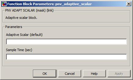
The name of the default adapted scalar output value (e.g., vftc_myscalar). The adaptive block reverts to this value when the reset inport is asserted or when the block data is unrecoverable during power initialisation of the ECU.
Value type: Real Calibratable: Yes, offline and online The periodicity of the block execution.
Range: [0.001, 3600] seconds
Value type: Real Calibratable: No
The build process generates a corresponding ASAP2 entry to the adaptive parameter that can be accessed via a calibration tool. The name of this entry has a fifth character 'a', i.e., given the default parameter name
vftc_myscalar, an ASAP2 entry with namevftca_myscalaris generated. Note that this implies that only a single adaptable value can exist per named default parameter.
Warning
If two or more blocks refer to the same named item in the Adaptive Scalar (default) field, these blocks will independently adapt the same adaptive parameter.
Adaptive array non-volatile storage.
None (Main library). (See Section 1.3, “Licensed Features”.)
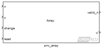
Sets outport u' to the value of the adapted array indexed by inport n. Before outport u is set, the value of indexed adapted array can be changed to inport u.
The target non-volatile memory is provided in two ways: either through storage that requires an external power source when the ECU is powered down (battery backed RAM storage), or not (Flash storage). See the technical specification for details on which storage type is supported by each target.
The battery backed non-volatile memory requires a small amount of power overall, i.e., much less than powering the ECU normally.
The adaptive data is check-summed using a 16-bit CRC. Failure to match the check-sums on start-up means that the data cannot be recovered. In this case, or if the model is simulated, adaptive data is reverted to the default value specified when the model was built.
The nth element in the array to modify.
Range: [0, number of elements in array - 1]
Value type: Integer Calibratable: No The value to write to the nth element of the array. The type of this inport is the same as the type of the parameter Array Data (default).
Value type: Real Calibratable: No 1 if the nth element of the array should be change to inport u, 0 otherwise. If the inport reset is 1, no change will occur (even if inport change is 1).
Range: 0 or 1
Value type: Boolean Calibratable: No 1 to change the array to the values of the Array Data (default) parameter, 0 otherwise.
Range: 0 or 1
Value type: Boolean Calibratable: No
1 if inport n refers to an element in the array, 0 if inport n is larger than the number of array elements.
Value type: Boolean Calibratable: No The value of the nth element of the array, possibly after the array has been changed. The type of this outport is the same as the type of the parameter Array Data (default).
Value type: Real Calibratable: No The current values of all elements of the array, possibly after the array has been changed, output as a vector. The type of this outport is the same as the type of the parameter Array Data (default). This outport is only present when the Output entire array contents? mask parameter checkbox is ticked.
Value type: Dynamically Typed Calibratable: No
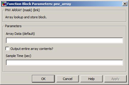
The name of the DDE for the array (e.g.
vftv_array, see Section "Naming rules"). An array can contain one or more elements. The type of the array dictates the type of inport u and outport u'.Value type: Real Calibratable: Yes, offline and online Tick this checkbox to create an outport from the block to output the entire array contents.
Value type: Boolean Calibratable: No The periodicity of the block execution.
Range: [0.001, 3600] seconds
Value type: Real Calibratable: No
The build process generates a corresponding ASAP2 entry to the adaptive parameter that can be accessed via a calibration tool. The name of this entry has a fifth character 'a', i.e., given the default parameter name
vtfv_array, an ASAP2 entry with namevtfva_arrayis generated. Note that this implies that only a single adaptive parameter can exist per named default parameter.Warning
If two or more blocks refer to the same named item in the Array Data (default) field, these blocks will independently adapt the same adaptive parameter.
Provide information about the state of non-volatile memories.
None (Main library). (See Section 1.3, “Licensed Features”.)
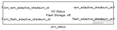
The non-volatile status block details the state of all non-volatile memories. For most ECUs, only flash storage is present.
Value passed through to outport ram_adaptive_checksum_ok when running the model under simulation. Has no effect when running on the target ECU.
Range: 0 or 1
Value type: Boolean Calibratable: No sim_flash_adaptive_checksum_ok
Value passed through to outport flash_adaptive_checksum_ok when running the model under simulation. Has no effect when running on the target ECU.
Range: 0 or 1
Value type: Boolean Calibratable: No
1 if the battery-backed RAM adaptive data check-sum is valid and up to date, 0 otherwise. If the adaptive data check-sum is invalid or inconsistent with the data stored in the battery backed RAM at model start up, the adaptive data is reverted to default - see help on the following adaptive data blocks: adaptive checksum, scalar, 1-d or 2-d maps, or arrays.
Range: 0 or 1
Value type: Boolean Calibratable: No 1 if the adaptive data check-sum is valid either at start up or after a NVM update, 0 otherwise. If the adaptive data check-sum is invalid at model start up, the adaptive data is reverted to default - see help on the following adaptive data blocks: adaptive checksum, scalar, 1-d or 2-d maps, or arrays.
Range: 0 or 1
Value type: Boolean Calibratable: No
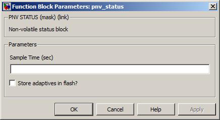
Enable or disable the output drivers.
None (Main library). (See Section 1.3, “Licensed Features”.)
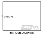
The output control block enables or disables some of the output driver devices on the target hardware.
If the pss_OutputControl block is not present in a model, then the output drivers are enabled when the model starts.
M250 ECUs
On the M250 ECUs, the output control block turns on or off the high side switches (pin A16) from which individual actuators can be attached. The choice of actuators which are directly controlled by this block is under the control of the system designer.
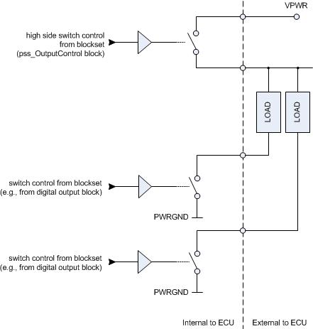
M460 ECU
On the M460 ECU, the output control block turns on or off the high side switches (pins A19, A29, A39, A40) from which individual actuators can be attached. The choice of actuators which are directly controlled by this block is under the control of the system designer.
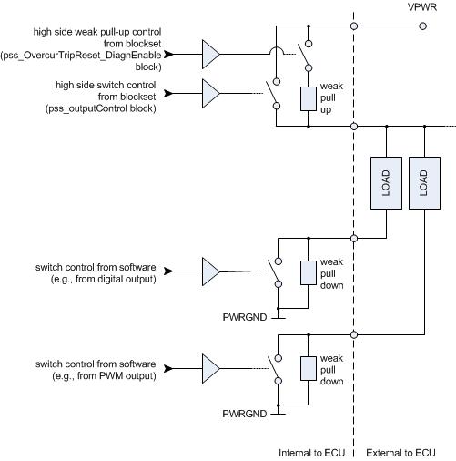
See Section 6.1.72, “Over current trip reset and diagnostic enable (pss_OvercurTripReset_DiagnEnable)” for a method to use the weak pull-up and pull-down resistors to diagnose issues with the connected actuators.
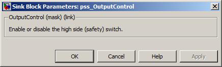
Provide access to the over-current trip latch reset functionality.
None (Main library). (See Section 1.3, “Licensed Features”.)
Over-current trip latch reset — when the overcur_trip_reset inport transitions from 0 to 1, the block records a request to clear the over-current trip latches. See the technical specification for the target ECU for details regarding the over-current trip latches.
Change from 0 to 1 to request a reset of the over-current trip latches. The request is buffered by the blockset and actioned when enough time has past since the last over-current trip reset (ensuring time for sufficient ECU heat dissipation).
Range: 0 or 1
Value type: Boolean Calibratable: No
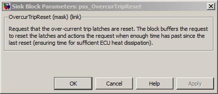
Provide access to the over-current trip latch reset functionality and high side (safety switch) diagnostic enable switch.
None (Main library). (See Section 1.3, “Licensed Features”.)
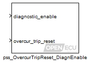
High side (safety switch) diagnostic enable — the diagnostic_enable inport controls the switch for a weak pull-up resistor in parallel with the high side switch. This functionality is only implemented on M460 target, see the technical specification for M460 for details on the high side diagnostic functionality.
Over-current trip latch reset — when the overcur_trip_reset inport transitions from 0 to 1, the block records a request to clear the over-current trip latches. See the technical specification for the target ECU for details regarding the over-current trip latches.
If the pss_OvercurTripReset_DiagnEnable block is not present in a model, then the high side diagnostic weak pull-up resistor switch is initialised open by the blockset when the ECU starts to run the model.
Set to 1 to close the high side diagnostic weak pull-up resistor switch, set to 0 to open the switch.
Range: 0 or 1
Value type: Boolean Calibratable: No Change from 0 to 1 to request a reset of the over-current trip latches. The request is buffered by the blockset and actioned when enough time has past since the last over-current trip reset (ensuring time for sufficient ECU heat dissipation).
Range: 0 or 1
Value type: Boolean Calibratable: No
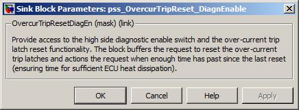
Control a peak and hold injector.
None (Main library). (See Section 1.3, “Licensed Features”.)
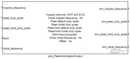
The peak and hold injector output block causes a stepped current signal to be generated at the selected injector frequency, in which the current is firstly controlled to the peak current threshold for the duration determined by the peak duty cycle, after which it is controlled to the hold current threshold for the remaining duration of the peak-hold duty cycle (i.e. the duration of the peak-hold duty cycle minus the peak duty cycle), after which the current falls to zero until the beginning of the next cycle.
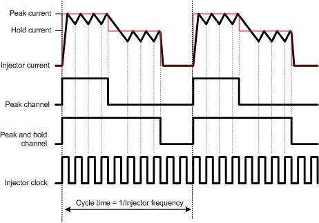
The injector frequency, clock frequency, peak duty cycle and peak-hold duty cycle are all driven from block inputs. The actual duty cycles are scaled by the mask parameter Min/Max duty cycle as follows:
output peak duty cycle = Minimum duty cycle + (Maximum duty cycle - Minimum duty cycle) * peak_duty_cycle
output peak-hold duty cycle = Minimum duty cycle + (Maximum duty cycle - Minimum duty cycle) * peak_hold_duty_cycle
Furthermore, the output peak-hold duty cycle is always constrained to be at least as great as the output peak duty cycle.
The channel output can be offset from other injector channels of the same frequency. The Offset parameter is used to delay the start of the injector cycle, so that the injector will not activate at the same time as other injector signals of the same frequency.
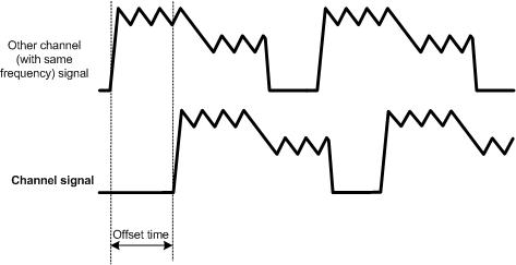
If the inport fault input is non-zero, then the output peak duty cycle is set to the mask parameter Peak default duty cycle and the output peak-hold duty cycle is set to the mask parameter Peak-hold default duty cycle.
The frequency of the injector cycles.
Range: [0.1, 1000] Hz
Value type: Real Calibratable: No After being rescaled by the mask parameter Min/Max duty cycle as described above, this is the ratio of the peak current time to the injector cycle time.
Range: [0, 1] duty-cycle
Value type: Real Calibratable: No After being rescaled by the mask parameter Min/Max duty cycle as described above, this is the ratio of the peak-hold current time to the injector cycle time.
Range: [0, 1] duty-cycle
Value type: Real Calibratable: No Set to 1 to force the block to use the default peak and peak-hold duty cycles, 0 otherwise.
Range: 0 or 1
Value type: Boolean Calibratable: No The frequency of the injector clock.
Range: [1, 10000] Hz
Value type: Real Calibratable: No
Only used in simulation. This outport is set to the calculated frequency for the injector cycles.
Range: [0.1, 1000] Hz
Value type: Real Calibratable: No Only used in simulation. This outport is set to the calculated duty cycle (after rescaling by the mask parameter Min/Max duty cycle as described above) for the peak channel.
Range: [0, 1] duty-cycle
Value type: Real Calibratable: No Only used in simulation. This outport is set to the calculated duty cycle (after rescaling by the mask parameters Min/Max duty cycle as described above) for the peak-hold channel. It is constrained to be at least as great as the peak duty cycle.
Range: [0, 1] duty-cycle
Value type: Real Calibratable: No Only used in simulation. This outport is set to the calculated frequency for the injector clock.
Range: [1, 10000] Hz
Value type: Real Calibratable: No
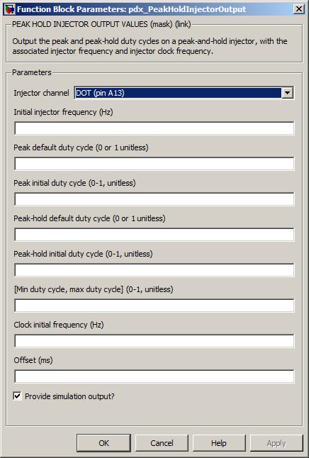
The injector channel for this block. The peak, peak-hold and injector clock channels are automatically assigned based on this.
Value type: List Calibratable: No The frequency of the channel signal before the block first iterates.
Range: [0.1, 1000] Hz
Value type: Real Calibratable: Yes, offline This is the final duty cycle of the peak signal when inport fault is set. The duty cycle is mapped directly to the output channel.
Range: 0 or 1 duty-cycle
Value type: Real Calibratable: Yes, offline and online The duty cycle of the peak signal (prior to rescaling by Min/Max duty cycle) before the block has first been executed.
Range: [0, 1] duty-cycle
Value type: Real Calibratable: Yes, offline This is the final duty cycle of the peak-hold signal when inport fault is set. The duty cycle is mapped directly to the output channel.
Range: 0 or 1 duty-cycle
Value type: Boolean Calibratable: Yes, offline and online The duty cycle of the peak-hold signal (prior to rescaling by Min/Max duty cycle) before the block has first been executed.
Range: [0, 1] duty-cycle
Value type: Real Calibratable: Yes, offline The frequency of the injector clock signal before the block first iterates.
Range: [1, 10000] Hz
Value type: Real Calibratable: Yes, offline Defines the lower and upper end of the window into which the input duty cycles are rescaled before use. The lower limit must be in the range 0 to (upper limit - 0.1). Similarly the upper limit must be in the range (lower limit + 0.1) to 1.0.
Range: [0, 1] duty-cycle
Value type: Real Calibratable: Yes, offline and online The desired phase offset, in milliseconds, of the injector output, relative to other injector output channels that have been configured with the same frequency.
Range: [0, 10000] ms
Value type: Integer Calibratable: Yes, offline and online
Get the recoverable error information for the ECU's free running internal RAM test.
None (Main library). (See Section 1.3, “Licensed Features”.)

Gets the recoverable error status of the ECU's internal RAM test as well as the address of the last error.
Only used under simulation and when the parameter Provide simulation inports is ticked. The outport error_detected is set to the value of this inport for simulation purposes.
Range: [0, 1]
Only used under simulation and when the parameter Provide simulation inports is ticked. The outport error_address is set to the value of this inport for simulation purposes.
Range: [0, 4294967295]
1 when a recoverable memory test error has been detected, 0 otherwise. Under simulation, if the Provide simulation inports parameter isn't ticked, the outport is set to the minimum of its range. The signal attached to the outport must be set as ExportedGlobal.
Range: [0, 1]
The internal memory address where a recoverable error has been detected. The outport is only valid if error_detected is 1. Under simulation, if the Provide simulation inports parameter isn't ticked, the outport is set to the minimum of its range. The signal attached to the outport must be set as ExportedGlobal.
Range: [0, 4294967295]

The periodicity of the block execution.
Range: [0.001, 3600] seconds
Tick to enable inports sim_error_detected and sim_error_address.
Unrecoverable memory test errors are reported by the put_Reset block.
Get the progress information for the ECU's free running internal RAM test.
None (Main library). (See Section 1.3, “Licensed Features”.)

Gets the start address, end address, and current address of the ECU's internal RAM test. The test checks a fixed number of internal memory segments during each iteration of the model. The test starts over once it reaches the end address.
Only used under simulation and when the parameter Provide simulation inports is ticked. The outport start_address is set to the value of this inport for simulation purposes.
Range: [0, 4294967295]
Only used under simulation and when the parameter Provide simulation inports is ticked. The outport end_address is set to the value of this inport for simulation purposes.
Range: [0, 4294967295]
Only used under simulation and when the parameter Provide simulation inports is ticked. The outport current_address is set to the value of this inport for simulation purposes.
Range: [0, 4294967295]
The first address of the internal memory test. Under simulation, if the Provide simulation inports parameter isn't ticked, the outport is set to the minimum of its range. The signal attached to the outport must be set as ExportedGlobal.
Range: [0, 4294967295]
The last address of the internal memory test. Under simulation, if the Provide simulation inports parameter isn't ticked, the outport is set to the minimum of its range. The signal attached to the outport must be set as ExportedGlobal.
Range: [0, 4294967295]
The current address of the internal memory test. Under simulation, if the Provide simulation inports parameter isn't ticked, the outport is set to the minimum of its range. The signal attached to the outport must be set as ExportedGlobal.
Range: [0, 4294967295]

The periodicity of the block execution.
Range: [0.001, 3600] seconds
Tick to enable inports sim_start_address, sim_end_address and sim_current_address.
Get the recoverable error information for the ECU's free running internal ROM test.
None (Main library). (See Section 1.3, “Licensed Features”.)
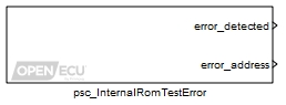
Gets the recoverable error status of the ECU's internal ROM test as well as the address of the last error.
Only used under simulation and when the parameter Provide simulation inports is ticked. The outport error_detected is set to the value of this inport for simulation purposes.
Range: [0, 1]
Only used under simulation and when the parameter Provide simulation inports is ticked. The outport error_address is set to the value of this inport for simulation purposes.
Range: [0, 4294967295]
1 when a recoverable memory test error has been detected, 0 otherwise. Under simulation, if the Provide simulation inports parameter isn't ticked, the outport is set to the minimum of its range. The signal attached to the outport must be set as ExportedGlobal.
Range: [0, 1]
The internal memory address where a recoverable error has been detected. The outport is only valid if error_detected is 1. Under simulation, if the Provide simulation inports parameter isn't ticked, the outport is set to the minimum of its range. The signal attached to the outport must be set as ExportedGlobal.
Range: [0, 4294967295]
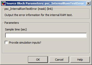
The periodicity of the block execution.
Range: [0.001, 3600] seconds
Tick to enable inports sim_error_detected and sim_error_address.
Unrecoverable memory test errors are reported by the put_Reset block.
Get the progress information for the ECU's free running internal ROM test.
None (Main library). (See Section 1.3, “Licensed Features”.)
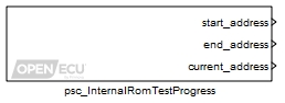
Gets the start address, end address, and current address of the ECU's internal ROM test. The test checks a fixed number of internal memory segments during each iteration of the model. The test starts over once it reaches the end address.
Only used under simulation and when the parameter Provide simulation inports is ticked. The outport start_address is set to the value of this inport for simulation purposes.
Range: [0, 4294967295]
Only used under simulation and when the parameter Provide simulation inports is ticked. The outport end_address is set to the value of this inport for simulation purposes.
Range: [0, 4294967295]
Only used under simulation and when the parameter Provide simulation inports is ticked. The outport current_address is set to the value of this inport for simulation purposes.
Range: [0, 4294967295]
The first address of the internal memory test. Under simulation, if the Provide simulation inports parameter isn't ticked, the outport is set to the minimum of its range. The signal attached to the outport must be set as ExportedGlobal.
Range: [0, 4294967295]
The last address of the internal memory test. Under simulation, if the Provide simulation inports parameter isn't ticked, the outport is set to the minimum of its range. The signal attached to the outport must be set as ExportedGlobal.
Range: [0, 4294967295]
The current address of the internal memory test. Under simulation, if the Provide simulation inports parameter isn't ticked, the outport is set to the minimum of its range. The signal attached to the outport must be set as ExportedGlobal.
Range: [0, 4294967295]
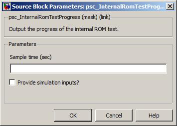
The periodicity of the block execution.
Range: [0.001, 3600] seconds
Tick to enable inports sim_start_address, sim_end_address and sim_current_address.
Get the build date for the ECU's platform code.
None (Main library). (See Section 1.3, “Licensed Features”.)
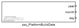
Gets the build date for the ECU's platform code. The build date can be used to distinguish between different versions of the platform code.
Only used under simulation and when the parameter Provide simulation inports is ticked. The outport year is set to the value of this inport for simulation purposes.
Range: [1970, 3000]
Only used under simulation and when the parameter Provide simulation inports is ticked. The outport month is set to the value of this inport for simulation purposes.
Range: [1, 12]
Only used under simulation and when the parameter Provide simulation inports is ticked. The outport day is set to the value of this inport for simulation purposes.
Range: [1, 31]
The year the platform code was built. Under simulation, if the Provide simulation inports parameter isn't ticked, the outport is set to the minimum of its range. The signal attached to the outport must be set as ExportedGlobal.
Range: [1970, 3000]
The month of the year the platform code was built. Under simulation, if the Provide simulation inports parameter isn't ticked, the outport is set to the minimum of its range. The signal attached to the outport must be set as ExportedGlobal.
Range: [1, 12]
The day of the month the platform code was built. Under simulation, if the Provide simulation inports parameter isn't ticked, the outport is set to the minimum of its range. The signal attached to the outport must be set as ExportedGlobal.
Range: [1, 31]

Get the version information for the ECU's platform code.
None (Main library). (See Section 1.3, “Licensed Features”.)
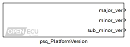
Gets the version information for the ECU's platform code. The version number is composed
of three fields, major, minor and sub-minor, typically written as major.minor.sub-minor.
The version can be used by the application for version control or diagnostics.
Only used under simulation and when the parameter Provide simulation inports is ticked. The outport major_ver is set to the value of this inport for simulation purposes.
Range: [0, 65535]
Only used under simulation and when the parameter Provide simulation inports is ticked. The outport minor_ver is set to the value of this inport for simulation purposes.
Range: [0, 65535]
Only used under simulation and when the parameter Provide simulation inports is ticked. The outport sub_minor_ver is set to the value of this inport for simulation purposes.
Range: [0, 65535]
The major version number of the platform code. Under simulation, if the Provide simulation inports parameter isn't ticked, the outport is set to the minimum of its range. The signal attached to the outport must be set as ExportedGlobal.
Range: [0, 65535]
The minor version number of the platform code. Under simulation, if the Provide simulation inports parameter isn't ticked, the outport is set to the minimum of its range. The signal attached to the outport must be set as ExportedGlobal.
Range: [0, 65535]
The sub-minor version number of the platform code. Under simulation, if the Provide simulation inports parameter isn't ticked, the outport is set to the minimum of its range. The signal attached to the outport must be set as ExportedGlobal.
Range: [0, 65535]
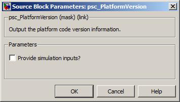
Tick to enable inports sim_major_ver, sim_minor_ver and sim_sub_minor_ver.
Get the part number information for the ECU's platform code.
None (Main library). (See Section 1.3, “Licensed Features”.)
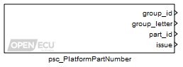
Gets the part number information for the ECU's platform code. The part number is composed
of four fields, group identification number, group identification letter, part identification number
and issue number, typically written as group_idgroup_letter-part_id Iss issue.
Example: 12T-168232 Iss 3
The part number can be used by the application for diagnostics, tracking and identification.
Only used under simulation and when the parameter Provide simulation inports is ticked. The outport group_id is set to the value of this inport for simulation purposes.
Range: [0, 255]
Only used under simulation and when the parameter Provide simulation inports is ticked. The outport group_letter is set to the value of this inport for simulation purposes.
Range: [0, 255]
Only used under simulation and when the parameter Provide simulation inports is ticked. The outport part_id is set to the value of this inport for simulation purposes.
Range: [0, 4294967295]
Only used under simulation and when the parameter Provide simulation inports is ticked. The outport issue is set to the value of this inport for simulation purposes.
Range: [0, 65535]
The Group Identification number of the part number of the platform code. Under simulation, if the Provide simulation inports parameter isn't ticked, the outport is set to the minimum of its range. The signal attached to the outport must be set as ExportedGlobal.
Range: [0, 255]
The Group Identification letter of the part number of the platform code. The value represents the ASCII code of the letter. Under simulation, if the Provide simulation inports parameter isn't ticked, the outport is set to the minimum of its range. The signal attached to the outport must be set as ExportedGlobal.
Range: [0, 255]
The Part Identification number of the part number of the platform code. Under simulation, if the Provide simulation inports parameter isn't ticked, the outport is set to the minimum of its range. The signal attached to the outport must be set as ExportedGlobal.
Range: [0, 4294967295]
The Issue number of the part number of the platform code. Under simulation, if the Provide simulation inports parameter isn't ticked, the outport is set to the minimum of its range. The signal attached to the outport must be set as ExportedGlobal.
Range: [0, 65535]
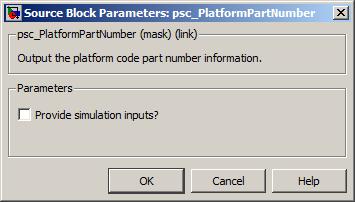
Tick to enable inports sim_group_id, sim_group_letter, sim_part_id and sim_issue.
Get the average processor loading for the running application.
None (Main library). (See Section 1.3, “Licensed Features”.)
Determines the load on the main processor over the last 50 milliseconds and the maximum load since the ECU was powered on (or last reset).
The load is calculated as the time used by any running task or interrupt over a 50 millisecond window, expressed as a percentage. The calculation is an estimate as the 50 millisecond window can extend over a wider duration if the processor is heavily loaded. As the 50 millisecond window does not synchronise with the model rate tasks, some aliasing can occur as well (for instance, one 50 millisecond window may contain only a small percentage of work done by the model, while another window may contain a higher percentage).
There is no provision to change the window duration for the loading calculation.
Only used under simulation and when the parameter Provide simulation inports is ticked. The outport loading is set to the value of this inport for simulation purposes.
Range: [0, 100] %
The processor loading over the last 50 milliseconds or the maximum processor loading seen since the ECU powered on (or reset). Under simulation, if the Provide simulation inports parameter isn't ticked, the outport is set to the minimum of its range.
Range: [0, 100] %
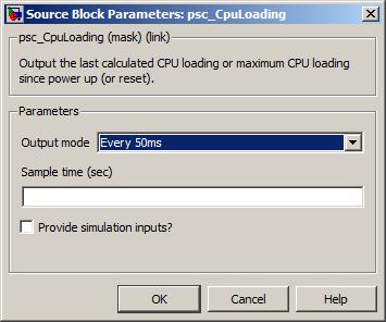
Whether the loading outport is set to the processor loading over 50 milliseconds, or the maximum loading since power on (or reset).
The periodicity of the block execution.
Range: [0.001, 3600] seconds
Tick to enable inport sim_loading.
Get the average eTPU loading for the running application.
None (Main library). (See Section 1.3, “Licensed Features”.)
Determines the load on each eTPU device over the last 50 milliseconds and the maximum load since the ECU was powered on (or last reset). The eTPU device, or devices, are used to process simple and complex I/O operations (such as decoding a crank wheel input).
The load is calculated as the time used by any running task or interrupt over a 50 millisecond window, expressed as a percentage. The calculation is an estimate as the 50 millisecond window can extend over a wider duration if the processor is heavily loaded. As the 50 millisecond window does not synchronise with the I/O operations, some aliasing can occur (for instance, one 50 millisecond window may contain only a small percentage of work done by the eTPU, while another window may contain a higher percentage).
There is no provision to change the window duration for the loading calculation.
Only used under simulation and when the parameter Provide simulation inports is ticked. The outport loading is set to the value of this inport for simulation purposes.
Range: [0, 100] %
The eTPU loading over the last 50 milliseconds or the maximum eTPU loading seen since the ECU last powered on (or last reset). Under simulation, if the Provide simulation inports parameter isn't ticked, the outport is set to the minimum of its range.
Range: [0, 100] %
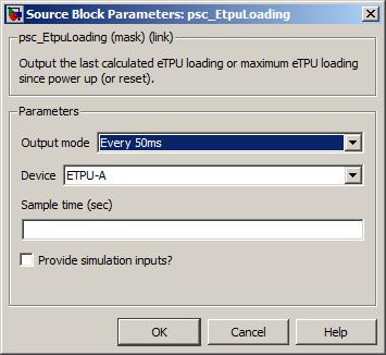
Whether the loading outport is set to the eTPU loading over 50 milliseconds, or the maximum loading since last power on (or last reset).
Which eTPU device to report on.
The periodicity of the block execution.
Range: [0.001, 3600] seconds
Tick to enable inport sim_loading.
Measure a PWM signal and derive the frequency and duty cycle.
None (Main library). (See Section 1.3, “Licensed Features”.)
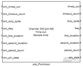
The input block measures a PWM signal and performs a number of operations:
- Frequency measurement
The block measures the time of each high and low (or low and high) pulse to determine the frequency of the input signal.

Whether the block measures a low pulse followed by a high pulse, or a high pulse followed by a low pulse is determined by the Invert block parameter.
- Pulse measurement
The block measures the durations of the first and second pulses and derives the duty cycle (first pulse time divided by the cycle time). Very small duty cycles (less than 1% or greater than 99%) will not be measured accurately or at all.
- Period count
The block accumulates the count of complete periods modulo 16777216. The application calculated difference of counts between iterations of the block could be used to diagnose unexpected changes in the signal.
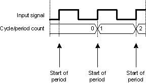
- Timeout check
The block measures the period duration and determines whether the signal has taken longer than the Time out duration. The block accumulates the count of time out events, and provides an outport to indicate if the signal is timed out when the block iterates.
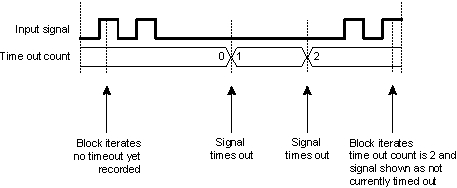
Only used in simulation. Place 1 here to simulate a time out, zero otherwise.
Range: 0 or 1
Value type: Boolean Only used in simulation. Place a count here to simulate the count of time outs in the input signal.
Range: [0, 16777215]
Value type: Integer Only used in simulation. Place a duty cycle here to simulate the duty cycle of the last measured period.
Range: [0, 1] duty-cycle
Value type: Real Only used in simulation. Place a frequency in Hz here to simulate the frequency of the last measured period.
Value type: Real Only used in simulation. Place a duration in microseconds here to simulate the first pulse from the last measured period.
Range: [0, 2000000] microseconds
Value type: Integer Only used in simulation. Place a duration in microseconds here to simulate the second pulse from the last measured period.
Range: [0, 2000000] microseconds
Value type: Integer Only used in simulation. Place a count here to simulate the count of periods seen in the input signal.
Range: [0, 16777215]
Value type: Integer Only used in simulation. Place a zero or 1 here to simulate the pin state sample.
Range: 0 or 1
Value type: Boolean
1 if a complete period has not been measured for the timeout given by the mask parameter Time out, zero otherwise.
Range: 0 or 1
Value type: Boolean A count of the time outs, wrapped modulo 16777216.
Range: [0, 16777215]
Value type: Integer Ratio of the first pulse duration to the period, or zero if no measurement has been taken.
Range: [0, 1] duty-cycle
Value type: Real Calibratable: No Frequency of the last measured period, or zero if no measurement has been taken. The range of the frequency is limited in various ways.
The range of the frequency that can be measured is limited by the filter circuitry of the input pin.
The lowest measurable frequency is limited by the filter circuitry and the size of the corresponding processor timer for a channel. Any input frequency below the documented limit, is reported as timed-out.
The highest measurable frequency is limited by the filter circuitry and the resolution of the corresponding processor timer for a channel. In general, the block reports the frequency of the filtered signal and the input filtering forms an upper limit. However, as the frequency increases, the resolution of measurement decreases.
Details of the input pin's filtering and processor timing can be found in an ECU's technical specification.
Range: [0.5, ...] Hz
Value type: Real The duration of the first pulse from the last measured period, or zero if no measurement has been taken.
Range: [0, 2000000] microseconds
Value type: Integer The duration of the second pulse from the last measured period, or zero if no measurement has been taken.
Range: [0, 2000000] microseconds
Value type: Integer A count of the periods, wrapped modulo 16777216.
Range: [0, 16777215]
Value type: Integer Calibratable: No Set to 1 if the input signal is high when the block iterates, set to zero if the input signal is low when the block iterates.
Range: 0 or 1
Value type: Boolean Calibratable: No
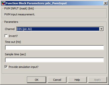
The input pin sourcing the signal to measure.
Value type: List Calibratable: No Whether the first pulse in the period will be high (option unticked) or low (option ticked). This option does not consider any inversion performed by the hardware, the user must do so.
Value type: Boolean Calibratable: No The period of time after which if no complete period has been measured, the outport timed_out is set to 1.
Range: [0.5, 10000] Hz
Value type: Real Calibratable: Yes, offline and online The periodicity of the block execution.
Range: [0.001, 3600] seconds
Value type: Real Calibratable: No If selected then create simulation inports for each of the outport message signals.
Value type: Boolean Calibratable: No
Pulse the output channel pin at a fixed frequency and variable duty cycle.
None (Main library). (See Section 1.3, “Licensed Features”.)
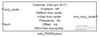
The PWM output block causes the channel output pin to oscillate at a desired frequency and duty cycle. The duty cycle is the High time divided by the Cycle time.
The actual state of the output pin is determined by the polarity of the pin. Some outputs are low-side only, some are high-side only, and some are software selectable. For software selectable pins, the polarity of the output can be selected by using the pdx_DigitalOutput block with the DOT select-high-side signal for the associated pin. Refer to the technical specification section for details on which pins support which polarities on each target.
Regardless of polarity, if the output is non-inverted, the output pin will be active during the High time and the output pin will be off (high impedance) during the Low time. If the output is inverted, the output will be active during the Low time and off during the High time.
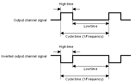
This block calculates the output duty cycle as:
output duty cycle = Minimum duty cycle + (Maximum duty cycle - Minimum duty cycle) * duty_cycle
If the Minimum duty cycle is 0 and the inport duty_cycle is 0, the output channel state is set low and does not oscillate. When the Maximum duty cycle is 1 and the inport Duty_cycle is 1, the output channel state is set high and does not oscillate.
The block supports 0% and 100% duty cycles, where the output signal no longer pulses. A 0% duty cycle is defined as High time equals zero and 100% duty cycle is defined as Low time equals zero.
The channel output pin state can be inverted in order to achieve the desired logical output state.
The channel output can be offset from other PWM channels of the same frequency. The {Offset} parameter is used to delay the start of the PWM cycle, so that the PWM pulse will not occur at the same time as other PWM signals of the same frequency.
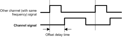
If the inport fault input is nonzero, then the output is set to the default duty cycle mask parameter. The default duty cycle is never inverted and can only be set to zero or one so care should be taken to chose the appropriate value to disable the output during a fault condition.
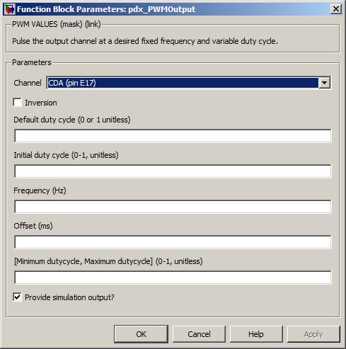
The channel pin for this pwm output.
Value type: List Calibratable: No Inverts the mapping of the input value to the channel pin. If inversion is ticked then a logical NOT operation is applied to the output state.
Value type: Boolean Calibratable: No This value is used if fault is active. The value is mapped directly to the output channel and is never inverted. Care should be taken to choose the appropriate value to drive the output off.
Range: 0 or 1 duty-cycle
Value type: Real Calibratable: Yes, offline and online The duty cycle that is output before the block has first been executed. This value is used in a similar way to Default duty cycle in that it is never inverted, however it can be set anywhere in the range 0 to 1.
Range: [0, 1] duty-cycle
Value type: Real Calibratable: Yes, offline and online The frequency of the pwm signal.
Range: [0.5, 10000] Hz
Value type: Real Calibratable: Yes, offline and online The desired phase offset, in milliseconds, of the PWM output, relative to other PWM output channels that have been configured with the same frequency.
Range: Target dependent
Target Range M110 Not supported M220 Not supported M221 Not supported M250 [0, 2000] ms M460 [0, 2000] ms M461 Not supported M670 Not supported Value type: Real Calibratable: Yes, offline Must be in the range 0 to (Maximum duty cycle - 0.1).
Range: [0, 0.9] duty-cycle
Value type: Real Calibratable: Yes, offline and online Must be in the range (Minimum duty cycle + 0.1) to 1.0.
Range: [0.1, 1] duty-cycle
Value type: Real Calibratable: Yes, offline and online Tick to enable outport sim_duty_cycle.
Value type: Boolean Calibratable: No
The resolution of the PWM channels depends on the output device (specified in the hardware target tables in Section A.1, “ECU hardware reference documentation”). Some channels have better resolution that others.
Some of the PWM output channels do not produce an accurate wave form when the duty cycle is either very small (e.g., 0.5%) or very large (e.g., 99.5%). All PWM output channels cope with 0% and 100% duty cycles correctly.
For the M250 target specifically, in order to avoid shoot-through and damage to the ECU when the mode switches, a 100us dead-time is inserted in the PWM signal for one task cycle at the beginning of mode-transition. Additionally, this dead-time insertion will only occur if the duty cycle that is commanded has a low time of less than 100us. For this reason, it will not be possible to command a 100% duty cycle during mode-transition for one task period.
Pulse the output channel pin at a variable frequency and duty cycle.
None (Main library). (See Section 1.3, “Licensed Features”.)
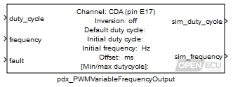
The PWM output block causes the channel output pin to oscillate at a desired frequency and duty cycle. A duty cycle is the High time divided by the Cycle time.
This block calculates the output duty cycle as:
output duty cycle = Minimum duty cycle + (Maximum duty cycle - Minimum duty cycle) * duty_cycle
If the Minimum duty cycle is 0 and the inport duty_cycle is 0, the output channel state is set low and does not oscillate. When the Maximum duty cycle is 1 and the inport Duty_cycle is 1, the output channel state is set high and does not oscillate.
The block supports 0% and 100% duty cycles, where the output signal no longer pulses. A 0% duty cycle is defined as High time equals zero and 100% duty cycle is defined as Low time equals zero.
The channel output pin state can be inverted in order to achieve the desired logical output state.
If the inport fault input is nonzero, then the output is set to the default duty cycle mask parameter (the default duty cycle is never inverted).
Ratio of the high time to the signal cycle time.
Range: [0, 1] duty-cycle
Value type: Real Frequency of the signal.
Range: [0.5, 10000] Hz
Value type: Real Place a 1 here to force the block to use the default frequency and duty cycle for the output, 0 otherwise.
Range: 0 or 1
Value type: Real
Only used in simulation. this outport is set to the processed duty cycle (i.e., duty_cycle or Initial duty cycle).
Value type: Real Only used in simulation. This outport is set to the processed frequency.
Value type: Real
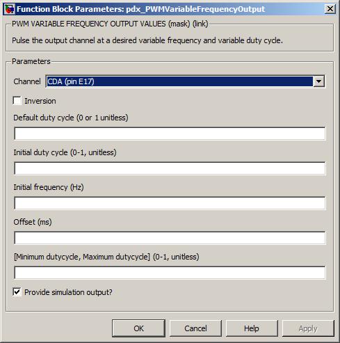
The channel pin for this pwm output.
Value type: List Calibratable: No Inverts the mapping of the input value to the channel pin. If inversion is set to 1 then a logical NOT operation is applied to the output state.
Value type: Boolean Calibratable: No This is the duty cycle of the channel when inport fault is set. The duty cycle is mapped directly to the output channel and is not inverted by parameter Inversion.
Range: [0, 1] duty-cycle
Value type: Real Calibratable: Yes, offline and online The duty cycle of the channel signal before the block has first been executed. This duty cycle is inverted if the mask parameter Inversion is set to 1.
Range: [0, 1] duty-cycle
Value type: Real Calibratable: Yes, offline The frequency of the PWM signal before the block first iterates.
Range: [0.5, 10000] Hz
Value type: Real Calibratable: Yes, offline The desired phase offset, in milliseconds, of the PWM output, relative to other PWM output channels that have been configured with the same frequency.
Range: Target dependent
Target Range M110 Not supported M220 Not supported M221 Not supported M250 [0, 2000] ms M460 [0, 2000] ms M461 Not supported M670 Not supported Value type: Real Calibratable: Yes, offline Must be in the range 0 to (Maximum duty cycle - 0.1).
Range: [0, 0.9] duty-cycle
Value type: Real Calibratable: Yes, offline and online Must be in the range (Minimum duty cycle + 0.1) to 1.0.
Range: [0.1, 1] duty-cycle
Value type: Real Calibratable: Yes, offline and online Tick to enable outport sim_duty_cycle and sim_frequency.
Value type: Boolean Calibratable: No
The resolution of the PWM channels depends on the output device (specified in the hardware target tables in Section A.1, “ECU hardware reference documentation”). Some channels have better resolution that others, notably the MIOS channels.
Some of the PWM output channels do not produce an accurate wave form when the duty cycle is either very small (e.g., 0.5%) or very large (e.g., 99.5%). All PWM output channels cope with 0% and 100% duty cycles correctly.
For the M250 target specifically, in order to avoid shoot-through and damage to the ECU when the mode switches, a 100us dead-time is inserted in the PWM signal for one task cycle at the beginning of mode-transition. Additionally, this dead-time insertion will only occur if the duty cycle that is commanded has a low time of less than 100us. For this reason, it will not be possible to command a 100% duty cycle during mode-transition for one task period.
Pulse the output channel pin at a variable frequency and duty cycle, while also sampling an analog input synchronously with the output waveform.
None (Main library). (See Section 1.3, “Licensed Features”.)

The PWM output block causes the channel output pin to oscillate at a desired frequency and duty cycle. A duty cycle is the High time divided by the Cycle time.
This block calculates the output duty cycle as:
output duty cycle = Minimum duty cycle + (Maximum duty cycle - Minimum duty cycle) * duty_cycle
If the Minimum duty cycle is 0 and the inport duty_cycle is 0, the output channel state is set low and does not oscillate. When the Maximum duty cycle is 1 and the inport Duty_cycle is 1, the output channel state is set high and does not oscillate.
The block supports 0% and 100% duty cycles, where the output signal no longer pulses. A 0% duty cycle is defined as High time equals zero and 100% duty cycle is defined as Low time equals zero.
The channel output pin state can be inverted in order to achieve the desired logical output state.
If the inport fault input is nonzero, then the output is set to the default duty cycle mask parameter (the default duty cycle is never inverted).
Ratio of the high time to the signal cycle time.
Range: [0, 1] duty-cycle
Value type: Real Frequency of the signal.
Range: [0.5, 10000] Hz
Value type: Real Place a 1 here to force the block to use the default frequency and duty cycle for the output, 0 otherwise.
Range: 0 or 1
Value type: Real Only used in simulation. When the model is simulated, the outport average_voltage is set to the value of this inport.
Range: [0, 5] volts
Value type: Real

The channel pin for this pwm output.
Value type: List Calibratable: No Inverts the mapping of the input value to the channel pin. If inversion is set to 1 then a logical NOT operation is applied to the output state.
Value type: Boolean Calibratable: No This is the duty cycle of the channel when inport fault is set. The duty cycle is mapped directly to the output channel and is not inverted by parameter Inversion.
Range: [0, 1] duty-cycle
Value type: Real Calibratable: Yes, offline and online The duty cycle of the channel signal before the block has first been executed. This duty cycle is inverted if the mask parameter Inversion is set to 1.
Range: [0, 1] duty-cycle
Value type: Real Calibratable: Yes, offline The frequency of the PWM signal before the block first iterates.
Range: [0.5, 10000] Hz
Value type: Real Calibratable: Yes, offline The desired phase offset, in milliseconds, of the PWM output, relative to other PWM output channels that have been configured with the same frequency.
Range: [0, 2000] ms (for the M250, M460 targets)
Value type: Real Calibratable: Yes, offline Must be in the range 0 to (Maximum duty cycle - 0.1).
Range: [0, 1] duty-cycle
Value type: Real Calibratable: Yes, offline and online Must be in the range (Minimum duty cycle + 0.1) to 1.0.
Range: [0, 1] duty-cycle
Value type: Real Calibratable: Yes, offline and online The channel pin to sample synchronously with the PWM output.
Value type: List Calibratable: No The number of samples to average and return by the average_voltage outport.
Value type: Integer Calibratable: Yes, offline and online The desired sampling point of the analog input relative to the PWM output signal. The sampling point is during the selected phase (high or low) of the PWM output signal. Normally 0.5 to sample at the center of the PWM phase.
Range: [0, 1] percentage
Value type: Real Calibratable: Yes, offline and online The desired sampling phase of the analog input relative to the PWM output signal.
Value type: List Calibratable: No
Output the number of edges sensed from the quadrature encoder since the last time the block iterated.
None (Main library). (See Section 1.3, “Licensed Features”.)
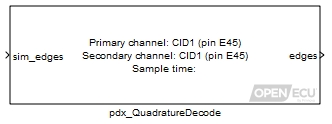
This block decodes the signals from a quadrature encoder. A quadrature encoder generates a pulse train from two sensors which pick up markings on the encoder disk.
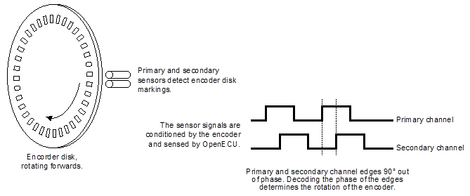
The sensors and markings are arranged so that when the encoder is turning, the sensor signals generate two pulse trains 90° out of phase. If the disk is turning in a forwards direction, the primary channel edges will lead the secondary channel edges. If the disk is turning in a backwards direction then the primary channel edges will lag the secondary channel edges. If there are no signal edges on either channel after a period of time, then the encoder has stopped turning (or is turning slowly enough to be considered stationary).
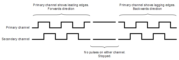
The quadrature decode block measures the primary and secondary channels, determines the direction at each pulse and counts the pulses. If the encoder is turning forwards then for each edge on the primary and secondary channels, the block increments the count. If the encoder is turning backwards then for each edge on the primary and secondary channels, the block decrements the count. When the block iterates, it outputs the count of pulses and resets the count to zero.
For instance, if the encoder turns forwards for nine edges between iterations of the block, the block output will be nine. If the encoder turns forwards for six edges and then backwards for two edges between executions of the block, the block output will be four.
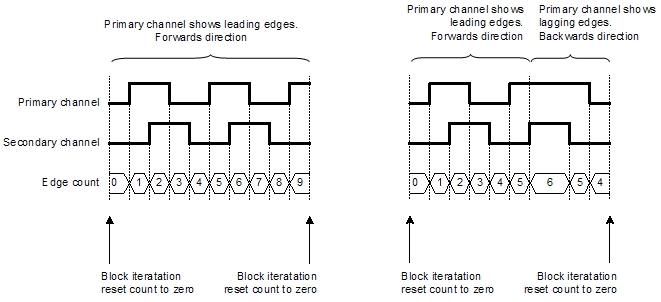
Note
Some encoders provide an index signal and some encoders provide complement signals of the primary and secondary signals, both for the purposes of improving reliability. This block does not decode these signals.
Only used in simulation. place the sum of edges here to simulate the number of edges sensed since the last iteration of this block. A value of zero indicates that the encoder position is at the same place as it was when the block was last iterated.
Range: [-8388608, 8388607] edges (for M221, M250, M460, M461 and M670 targets)
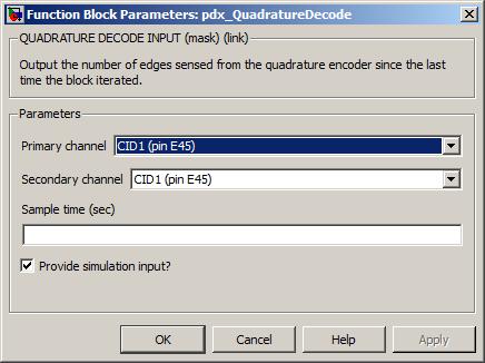
The input pin sourcing the primary signal to measure. The relationship between the primary and secondary channels is explained above.
The input pin sourcing the secondary signal to measure. The relationship between the primary and secondary channels is explained above.
The periodicity of the block iterations.
Range: [0.001, 3600] seconds
If the edges_sensed outport is zero, it means the encoder position is in the same position as it was when the block was last iterated. This can occur if the encoder position has not moved, or if the encoder position has moved and returned to its original position. This should be kept in mind if the block will be used to derive the encoder's velocity.
The block iteration period must be sufficient to ensure that the sum of leading and lagging edges is no more than 32767 between iterations of the block. If the sum of edges is greater than 32767 then the edges_sensed outport will contain the sum of edges modulo 32768.
Output the number of edges sensed from the quadrature encoder since the last time the block iterated. Output the last measured frequency of the primary and secondary channels.
None (Main library). (See Section 1.3, “Licensed Features”.)
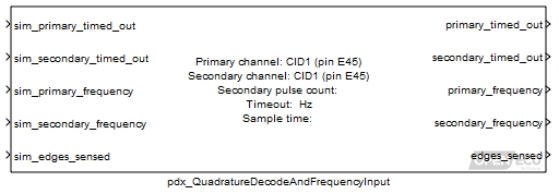
This block decodes the signals from a quadrature encoder. A quadrature encoder generates a pulse train from two sensors which pick up markings on the encoder disk.
The sensors and markings are arranged so that when the encoder is turning, the sensor signals generate two pulse trains 90° out of phase. If the disk is turning in a forwards direction, the primary channel edges will lead the secondary channel edges. If the disk is turning in a backwards direction then the primary channel edges will lag the secondary channel edges. If there are no signal edges on either channel after a period of time, then the encoder has stopped turning (or is turning slowly enough to be considered stationary).
The quadrature decode block measures the primary and secondary channels, determines the direction at each pulse and counts the pulses. If the encoder is turning forwards then for each edge on the primary and secondary channels, the block increments the count. If the encoder is turning backwards then for each edge on the primary and secondary channels, the block decrements the count. When the block iterates, it outputs the count of pulses and resets the count to zero.
For instance, if the encoder turns forwards for nine edges between iterations of the block, the block output will be nine. If the encoder turns forwards for six edges and then backwards for two edges between executions of the block, the block output will be four.
Note
Some encoders provide an index signal and some encoders provide complement signals of the primary and secondary signals, both for the purposes of improving reliability. This block does not decode these signals.
The block also measures the duration of each pulse from the encoder primary and secondary channels and outputs the last measured frequency of each channel. If the frequency of a channel has not been measured (because a complete signal pulse has not yet occurred), then the corresponding frequency outport is set to zero.
If the primary or secondary channel does not complete a pulse for longer than the block's timeout value, then the corresponding primary_timed_out and secondary_timed_out outports of the block are set. When a timeout occurs, the frequency outport for that channel remains at its last known frequency measurement (or zero if a measurement has not been completed).
Only used in simulation. Place 1 here to simulate a time out for the primary channel frequency measurement, 0 otherwise.
Range: 0 or 1
Only used in simulation. Place 1 here to simulate a time out for the secondary channel frequency measurement, 0 otherwise.
Range: 0 or 1
Only used in simulation. Place the frequency in hertz here to simulate the last measured primary channel frequency. A measurement of zero hertz indicates that no measurement is available.
Only used in simulation. Place the frequency in hertz here to simulate the last measured secondary channel frequency. A measurement of zero hertz indicates that no measurement is available.
Only used in simulation. Place the count of edges here to simulate the number of edges sensed since the last execution of this block. A value of zero indicates that the encoder position is at the same place as it was when the block was last iterated.
Range: [-8388608, 8388607] edges (for M221, M250, M460, M461, and M670 targets)
1 if the primary channel input signal has not completed a pulse within the mask parameter timeout period at the point of sampling (see the mask parameter section below), 0 otherwise.
Range: 0 or 1
1 if the secondary channel input signal has not completed a pulse within the mask parameter timeout period at the point of sampling (see the mask parameter section below), 0 otherwise.
Range: 0 or 1
The last measured primary channel frequency in hertz, or 0 if no measurement has been taken (regardless of the state of outport primary_timed_out). The range of the frequency is limited in various ways.
The range of the frequency that can be measured is limited by the filter circuitry of the input pin.
The lowest measurable frequency is limited by the filter circuitry and the size of the corresponding processor timer for a channel. Any input frequency below the documented limit, is reported as timed-out.
The highest measurable frequency is limited by the filter circuitry and the resolution of the corresponding processor timer for a channel. In general, the block reports the frequency of the filtered signal and the input filtering forms an upper limit. However, as the frequency increases, the resolution of measurement decreases.
Details of the input pin's filtering and processor timing can be found in an ECU's technical specification.
Range: [0.5, ...] Hz (for M221, M250, M460, M461 and M670 targets)
The last measured secondary channel frequency in hertz, or 0 if no measurement has been taken (regardless of the state of outport secondary_timed_out).
Range: [0.5, ...] Hz (for M221, M250, M460, M461 and M670 targets)
The count of edges sensed since the last time the block was iterated. A value of zero indicates that the the encoder position is at the same place as it was when the block was last iterated.
Range: [-8388608, 8388607] edges (for M221, M250, M460, M461 and M670 targets)
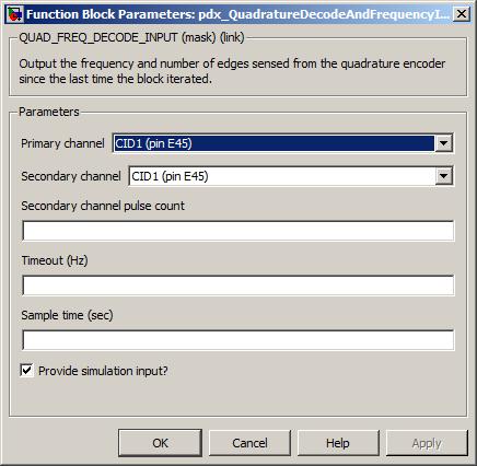
The input pin sourcing the primary signal to measure. The relationship between the primary and secondary channels is explained above.
The input pin sourcing the secondary signal to measure. The relationship between the primary and secondary channels is explained above.
The number of pulses to accumulate when calculating the frequency for the secondary input channel. The primary channel frequency is always calculated by measuring one complete pulse.
Range: [1, 255] pulses
The period of time in hertz after which if no complete pulse has been measured for the primary or secondary channel, the corresponding outports primary_timed_out and secondary_timed_out are set to 1.
Range: [0.5, 10000] Hz (for M221, M250, M460, M461 and M670 targets)
The periodicity of the block iteration.
Range: [0.001, 3600] seconds
If the edges_sensed outport is zero, it means the encoder position is in the same position as it was when the block was last iterated. This can occur if the encoder position has not moved, or if the encoder position has moved and returned to its original position. This should be kept in mind if the block will be used to derive the encoder's velocity.
The block iteration period must be sufficient to ensure that the sum of leading and lagging edges is no more than 8388607 (for M221, M250, M460, M461 and M670 targets) between iterations of the block. If the sum of edges is greater then the edges_sensed outport will wrap with modulo arithmetic, (24-bit for M221, M250, M460, M461 and M670 targets).
The primary and secondary frequency outports may differ in value due to hardware filtering. A specific example of this would be where the two channels have differing low pass filters such that the input signals are cut off at different frequencies.
Range check the input and provide fault information from the range check.
None (Main library). (See Section 1.3, “Licensed Features”.)
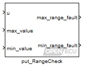
Value to range check.
A value of u greater than this causes the outport max_range_fault to become set.
A value of u less than this causes the outport min_range_fault to become set.
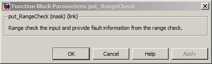
Provide reset information and a mechanism to reset the ECU.
None (Main library). (See Section 1.3, “Licensed Features”.)
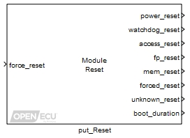
Allow the user to force the module to reset. Provide information about the previous reset event including how long the module took to start iterating the model.
Set to 1 if the last reset event was from a power up event, 0 otherwise.
Set to 1 if the last reset event was due to the ECU's processor watchdog, 0 otherwise.
Set to 1 if the last reset event was due to incorrect software in the model or platform accessing a memory area in the controller that did not exist, 0 otherwise.
Set to 1 if the last reset event was due to incorrect software in the model that attempted to manipulate a floating point value in a way the ECU's processor determined as invalid, 0 otherwise. Note that floating point exceptions are not enabled on all platforms and as such the lack of a floating point reset is not sufficient to prove that the model is free from floating point manipulation errors.
Set to 1 if the last reset event was due to an unrecoverable corruption of internal memory, 0 otherwise. The cause of a reset that occurs as a result of memory corruption may not always be identified by software. If the cause cannot be identified by the platform software, then the reset will be reported by the unknown_reset outport.
Set to 1 if the last reset event was due to a forced model reset, 0 otherwise.
Set to 1 if the last reset event could not be determined, 0 otherwise.
A rough indication of how long the module took to boot (i.e., from processor start to starting the first model iteration) in seconds. Only if the version of boot is sufficient (version 1.0.7 or greater) will this outport contain a value. If the boot version is not sufficient, the outport is set to zero.
Note
The duration from power up to processor start is not part of boot_duration. It varies based on the environmental conditions but is usually around 40ms to 80ms in duration. The boot duration will increase as the calibration size increases.
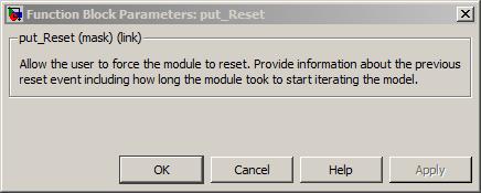
Get the free running count of the number of powered resets.
None (Main library). (See Section 1.3, “Licensed Features”.)
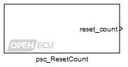
Get the free running count of the number of powered resets since power on. The count is reset upon power cycle.
Only used under simulation and when the parameter Provide simulation inputs is ticked. The outport reset_count is set to the value of this inport for simulation purposes.
Range: 0 to 4294967295.
The number of resets since the ECU was powered on. Under simulation, if the Provide simulation inputs parameter isn't ticked, the outport is set to the minimum of its range.
Range: 0 to 4294967295.
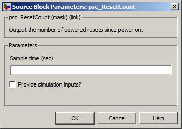
The periodicity of the block execution.
Range: [0.001, 3600] seconds
Value type: Real Calibratable: No Tick to enable inport sim_count.
Get the count of the number of unstable powered resets.
None (Main library). (See Section 1.3, “Licensed Features”.)
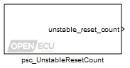
Get the limited counter of the number of powered resets that occur within 60 seconds of initialisation. It is cleared once the application been running for at least 60 seconds. If the unstable reset counter reaches a threshold defined in the platform, then the module will be forced in to reprogramming mode.
Only used under simulation and when the parameter Provide simulation inputs is ticked. The outport unstable_reset_count is set to the value of this inport for simulation purposes.
Range: 0 to 4.
The number of unstable resets since the ECU was powered on. Under simulation, if the Provide simulation inputs parameter isn't ticked, the outport is set to the minimum of its range.
Range: 0 to 4.
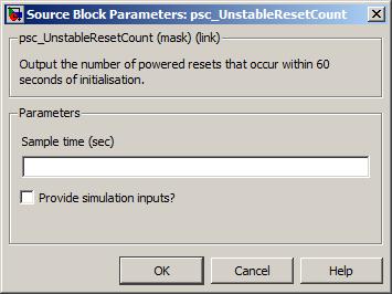
The periodicity of the block execution.
Range: [0.001, 3600] seconds
Value type: Real Calibratable: No Tick to enable inport sim_count.
Get the build date for the ECU's reprogramming code.
None (Main library). (See Section 1.3, “Licensed Features”.)
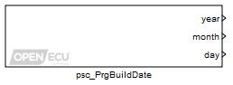
Gets the build date for the ECU's reprogramming code. The build date can be used to distinguish between different versions of the reprogramming code.
Only used under simulation and when the parameter Provide simulation inports is ticked. The outport year is set to the value of this inport for simulation purposes.
Range: [1970, 3000]
Only used under simulation and when the parameter Provide simulation inports is ticked. The outport month is set to the value of this inport for simulation purposes.
Range: [1, 12]
Only used under simulation and when the parameter Provide simulation inports is ticked. The outport day is set to the value of this inport for simulation purposes.
Range: [1, 31]
The year the reprogramming code was built. Under simulation, if the Provide simulation inports parameter isn't ticked, the outport is set to the minimum of its range. The signal attached to the outport must be set as ExportedGlobal.
Range: [1970, 3000]
The month of the year the reprogramming code was built. Under simulation, if the Provide simulation inports parameter isn't ticked, the outport is set to the minimum of its range. The signal attached to the outport must be set as ExportedGlobal.
Range: [1, 12]
The day of the month the reprogramming code was built. Under simulation, if the Provide simulation inports parameter isn't ticked, the outport is set to the minimum of its range. The signal attached to the outport must be set as ExportedGlobal.
Range: [1, 31]
Get the version information for the ECU's reprogramming code.
None (Main library). (See Section 1.3, “Licensed Features”.)
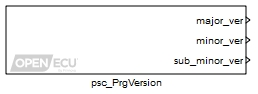
Gets the version information for the ECU's reprogramming code. The version number is composed
of three fields, major, minor and sub-minor, typically written as major.minor.sub-minor.
The version can be used by the application for version control or diagnostics.
Only used under simulation and when the parameter Provide simulation inports is ticked. The outport major_ver is set to the value of this inport for simulation purposes.
Range: [0, 65535]
Only used under simulation and when the parameter Provide simulation inports is ticked. The outport minor_ver is set to the value of this inport for simulation purposes.
Range: [0, 65535]
Only used under simulation and when the parameter Provide simulation inports is ticked. The outport sub_minor_ver is set to the value of this inport for simulation purposes.
Range: [0, 65535]
The major version number of the reprogramming code. Under simulation, if the Provide simulation inports parameter isn't ticked, the outport is set to the minimum of its range. The signal attached to the outport must be set as ExportedGlobal.
Range: [0, 65535]
The minor version number of the reprogramming code. Under simulation, if the Provide simulation inports parameter isn't ticked, the outport is set to the minimum of its range. The signal attached to the outport must be set as ExportedGlobal.
Range: [0, 65535]
The sub-minor version number of the reprogramming code. Under simulation, if the Provide simulation inports parameter isn't ticked, the outport is set to the minimum of its range. The signal attached to the outport must be set as ExportedGlobal.
Range: [0, 65535]
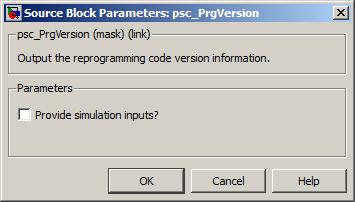
Tick to enable inports sim_major_ver, sim_minor_ver and sim_sub_minor_ver.
Get the part number information for the ECU's reprogramming code.
None (Main library). (See Section 1.3, “Licensed Features”.)
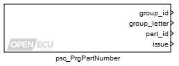
Gets the part number information for the ECU's reprogramming code. The part number is composed
of four fields: group identification number, group identification letter, part identification number
and issue number, typically written as group_idgroup_letter-part_id Iss issue.
Example: 12T-168232 Iss 3
The part number can be used by the application for diagnostics, tracking and identification.
Only used under simulation and when the parameter Provide simulation inports is ticked. The outport group_id is set to the value of this inport for simulation purposes.
Range: [0, 255]
Only used under simulation and when the parameter Provide simulation inports is ticked. The outport group_letter is set to the value of this inport for simulation purposes.
Range: [0, 255]
Only used under simulation and when the parameter Provide simulation inports is ticked. The outport part_id is set to the value of this inport for simulation purposes.
Range: [0, 4294967295]
Only used under simulation and when the parameter Provide simulation inports is ticked. The outport issue is set to the value of this inport for simulation purposes.
Range: [0, 65535]
The Group Identification number of the part number of the reprogramming code. Under simulation, if the Provide simulation inports parameter isn't ticked, the outport is set to the minimum of its range. The signal attached to the outport must be set as ExportedGlobal.
Range: [0, 255]
The Group Identification letter of the part number of the reprogramming code. The value represents the ASCII code of the letter. Under simulation, if the Provide simulation inports parameter isn't ticked, the outport is set to the minimum of its range. The signal attached to the outport must be set as ExportedGlobal.
Range: [0, 255]
The Part Identification number of the part number of the reprogramming code. Under simulation, if the Provide simulation inports parameter isn't ticked, the outport is set to the minimum of its range. The signal attached to the outport must be set as ExportedGlobal.
Range: [0, 4294967295]
The Issue number of the part number of the reprogramming code. Under simulation, if the Provide simulation inports parameter isn't ticked, the outport is set to the minimum of its range. The signal attached to the outport must be set as ExportedGlobal.
Range: [0, 65535]

Tick to enable inports sim_group_id, sim_group_letter, sim_part_id and sim_issue.
Given a key, search the registry for the corresponding data.
None (Main library). (See Section 1.3, “Licensed Features”.)
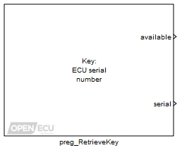
Given a key, selected through the Registry key mask parameter, the block searches through the ECU's registry to retrieve the key's data. If the key was found then the available outport is set to 1 and the remaing outports set to the key's data. If the key was not found then the available outport is set to zero.
Note
Not all ECUs are programmed with registry data. Older ECUs, do not contain registry data.
The registry contains a checksum. Failure of checksum verification results in the registry being unavailable.
Only used under simulation and when the parameter Provide simulation inports is ticked. The outport available is set to the value of this inport for simulation purposes.
Range: 0 or 1
Value type: Boolean Only used under simulation and when the parameter Provide simulation inports is ticked. The outport serial is set to the value of this inport for simulation purposes.
Range: [0, 4294967295]
Value type: Integer Only used under simulation and when the parameter Provide simulation inports is ticked. The outport shift is set to the value of this inport for simulation purposes.
Range: [1, 3]
Value type: Integer Only used under simulation and when the parameter Provide simulation inports is ticked. The outport day is set to the value of this inport for simulation purposes.
Range: [1, 31]
Value type: Integer Only used under simulation and when the parameter Provide simulation inports is ticked. The outport month is set to the value of this inport for simulation purposes.
Range: [1, 12]
Value type: Integer Only used under simulation and when the parameter Provide simulation inports is ticked. The outport year is set to the value of this inport for simulation purposes.
Range: [1970, 3000]
Value type: Integer Only used under simulation and when the parameter Provide simulation inports is ticked. The outport prefix is set to the value of this inport for simulation purposes.
Range: [0, 99]
Value type: Integer Only used under simulation and when the parameter Provide simulation inports is ticked. The outport id is set to the value of this inport for simulation purposes.
Range: ['A', 'Z'] ASCII character
Value type: Integer Only used under simulation and when the parameter Provide simulation inports is ticked. The outport part is set to the value of this inport for simulation purposes.
Range: [0, 999999]
Value type: Integer Only used under simulation and when the parameter Provide simulation inports is ticked. The outport issue is set to the value of this inport for simulation purposes.
Range: [0, 255]
Value type: Integer Only used under simulation and when the parameter Provide simulation inports is ticked. The outport mod is set to the value of this inport for simulation purposes.
Range: [0, 255]
Value type: Integer Only used under simulation and when the parameter Provide simulation inports is ticked. The outports fpart_a are set to the value of these inports for simulation purposes.
Range: [0, 65535]
Value type: Integer Only used under simulation and when the parameter Provide simulation inports is ticked. The outports fpart_b are set to the value of these inports for simulation purposes.
Range: [0, 65535]
Value type: Integer Only used under simulation and when the parameter Provide simulation inports is ticked. The outport fid_a is set to the value of this inport for simulation purposes.
Range: ['A', 'Z'] ASCII characters
Value type: Integer Only used under simulation and when the parameter Provide simulation inports is ticked. The outport fid_b is set to the value of this inport for simulation purposes.
Range: ['A', 'Z'] ASCII characters
Value type: Integer Only used under simulation and when the parameter Provide simulation inports is ticked. The outport build_type_a is set to the value of this inport for simulation purposes.
Range: ['A', 'Z'] ASCII characters
Value type: Integer Only used under simulation and when the parameter Provide simulation inports is ticked. The outport build_type_b is set to the value of this inport for simulation purposes.
Range: ['A', 'Z'] ASCII characters
Value type: Integer Only used under simulation and when the parameter Provide simulation inports is ticked and if the Registry key mask parameter is set to Generic. The outport value is set to the value of this inport for simulation purposes.
Size: 6
Range: [0, 255]
Value type: uint8_T vector
Whether the key could be retrieved or not. Under simulation, if the Provide simulation inports parameter isn't ticked, the outport is set to zero. The signal attached to the outport must be set as ExportedGlobal.
Range: 0 or 1
Value type: Boolean The ECU's serial number. Outport available if the Registry key mask parameter is set to ECU serial number. Under simulation, if the Provide simulation inports parameter isn't ticked, the outport is set to zero. The signal attached to the outport must be set as ExportedGlobal.
Range: [0, 4294967295]
Value type: Integer The team shift at the point of manufacture. Outport available if the Registry key mask parameter is set to ECU date of manufacture. Under simulation, if the Provide simulation inports parameter isn't ticked, the outport is set to zero. The signal attached to the outport must be set as ExportedGlobal.
Range: [1, 3]
Value type: Integer The day of the month at the point of manufacture. Outport available if the Registry key mask parameter is set to ECU date of manufacture. Under simulation, if the Provide simulation inports parameter isn't ticked, the outport is set to zero. The signal attached to the outport must be set as ExportedGlobal.
Range: [1, 31]
Value type: Integer The month of the year at the point of manufacture. Outport available if the Registry key mask parameter is set to ECU date of manufacture. Under simulation, if the Provide simulation inports parameter isn't ticked, the outport is set to zero. The signal attached to the outport must be set as ExportedGlobal.
Range: [1, 12]
Value type: Integer The year at the point of manufacture. Outport available if the Registry key mask parameter is set to ECU date of manufacture. Under simulation, if the Provide simulation inports parameter isn't ticked, the outport is set to zero. The signal attached to the outport must be set as ExportedGlobal.
Range: [1970, 3000]
Value type: Integer The prefix of the engineering part number, e.g., 01 from 01T-068165. Outport available if the Registry key mask parameter is set to ECU date of manufacture. Under simulation, if the Provide simulation inports parameter isn't ticked, the outport is set to zero. The signal attached to the outport must be set as ExportedGlobal.
Range: [0, 99]
Value type: Integer The letter of the engineering part number, e.g., T from 01T-068165. Outport available if the Registry key mask parameter is set to ECU date of manufacture. Under simulation, if the Provide simulation inports parameter isn't ticked, the outport is set to zero. The signal attached to the outport must be set as ExportedGlobal.
Range: ['A', 'Z'] ASCII character
Value type: Integer The remainder of the engineering part number, e.g., 068165 from 01T-068165. Outport available if the Registry key mask parameter is set to ECU date of manufacture. Under simulation, if the Provide simulation inports parameter isn't ticked, the outport is set to zero. The signal attached to the outport must be set as ExportedGlobal.
Range: [0, 999999]
Value type: Integer The ECU's PCB issue number, representing the PCB design. Outport available if the Registry key mask parameter is set to ECU PCB issue and modification number. Under simulation, if the Provide simulation inports parameter isn't ticked, the outport is set to zero. The signal attached to the outport must be set as ExportedGlobal.
Range: [0, 255]
Value type: Integer The ECU's PCB modification number, representing hand modifications to the PCB to match the PCB design intent. Outport available if the Registry key mask parameter is set to ECU PCB issue and modification number. Under simulation, if the Provide simulation inports parameter isn't ticked, the outport is set to zero. The signal attached to the outport must be set as ExportedGlobal.
Range: [0, 255]
Value type: Integer The pre numerical part to the factory part number, which represents a detailed build specification for the ECU. Outport available if the Registry key mask parameter is set to ECU factory part number. Under simulation, if the Provide simulation inports parameter isn't ticked, the outport is set to zero. The signal attached to the outport must be set as ExportedGlobal.
Range: [0, 65535]
Value type: Integer The post numerical part to the factory part number, which represents a detailed build specification for the ECU. Outport available if the Registry key mask parameter is set to ECU factory part number. Under simulation, if the Provide simulation inports parameter isn't ticked, the outport is set to zero. The signal attached to the outport must be set as ExportedGlobal.
Range: [0, 65535]
Value type: Integer The first letter identifier that separates the pre and post factory part number. Outport available if the Registry key mask parameter is set to ECU factory part number. Under simulation, if the Provide simulation inports parameter isn't ticked, the outport is set to zero. The signal attached to the outport must be set as ExportedGlobal.
Range: ['A', 'Z'] ASCII character
Value type: Integer The second letter identifier that separates the pre and post factory part number. Outport available if the Registry key mask parameter is set to ECU factory part number. Under simulation, if the Provide simulation inports parameter isn't ticked, the outport is set to zero. The signal attached to the outport must be set as ExportedGlobal.
Range: ['A', 'Z'] ASCII character
Value type: Integer The first letter of a two letter identifier representing the factory part number build type. Outport available if the Registry key mask parameter is set to ECU factory part number. Under simulation, if the Provide simulation inports parameter isn't ticked, the outport is set to zero. The signal attached to the outport must be set as ExportedGlobal.
Range: ['A', 'Z'] ASCII character
Value type: Integer The second letter of a two letter identifier representing the factory part number build type. Outport available if the Registry key mask parameter is set to ECU factory part number. Under simulation, if the Provide simulation inports parameter isn't ticked, the outport is set to zero. The signal attached to the outport must be set as ExportedGlobal.
Range: ['A', 'Z'] ASCII character
Value type: Integer The raw data bytes of the registry key matching the Generic key. Outport available if the Registry key mask parameter is set to Generic. Under simulation, if the Provide simulation inports parameter isn't ticked, each index of the outport is set to 0. This value is also output if outport available shows that the registry is unavailable. The signal attached to the outport must be set as ExportedGlobal.
Size: 6
Range: [0, 255]
Value type: uint8_T vector
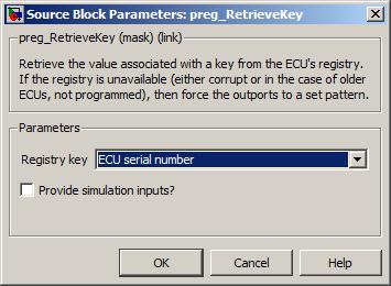
A drop down to specify the registry key to retrieve.
- Generic
The raw data of the key matching the Generic key parameter is returned.
- ECU serial
The serial number is a 32-bit positive integer. Serial numbers across different families of ECUs do not overlap.
- ECU date of manufacture
The date is composed as (shift) dd:mm:yy, where the shift identifies the team involved in the manufacturing process.
- ECU engineering part number
The engineering part number matches the pattern: prefix letter engineering-part-number. For instance, the engineering part number assigned to the M250-000 is 01T068165, where 01 represents the prefix, T represents the letter and 068165 represents the engineering part number.
- ECU PCB issue and modification number
The issue level represents a specific design of PCB. Changes to the issue level may have an effect on the platform library.
The modification level represents what changes were performed to the PCB after manufacturing to correct issue level design mistakes. Changes to the modification level should not have an effect on the platform library.
- ECU factory part number
The identifier for the build specification used to create the ECU, matching the pattern value letter value, e.g., 450FT1024.
- ECU factory part number build type
An indication of the build type, usually appended to the factory part number, e.g., 450FT1024-E2, where E2 indicates second spec. engineering build.
Value type: List Calibratable: No The generic key to read from the registry. Parameter available if the Registry key mask parameter is set to Generic.
Range: [0, 65535]
Value type: uint16_T Calibratable: Yes, offline Tick to enable simulation inports.
Value type: Boolean Calibratable: No
All the supported keys for the registry and their corresponding data is defined below. Each Registry key mask parameter selection points to a unique key except for the Generic key parameter which can be used to select any generic key. The table below shows which Registry key dropdown selection maps to which key and also shows the Key ID values that can be used if the Generic registry key is selected.
Note
All numeric values are stored in Motorola format (i.e. MSB first)
Table 6.5. Supported Key/Value pairs
| Registry Key Selection | Key ID | Data bytes | Description | |||||
|---|---|---|---|---|---|---|---|---|
| 0 | 1 | 2 | 3 | 4 | 5 | |||
| ECU serial number | 0x0001 | Unused | Serial Number | ECU Serial Number as Integer | ||||
| ECU date of manufacture | 0x0002 | Unused | Shift [1...3] | Day | Month | Year | Date of Manufacture | |
| ECU engineering part number | 0x0003 | Prefix U8 | Letter | Value U32 | ECU Engineering Part Number | |||
| ECU PCB issue and modification number | 0x0004 | Unused | H/W Issue | H/W Mod | HW Issue and Mod State | |||
| ECU factory part number | 0x0005 | Value U16 | Letter | Letter | Value U16 | Factory Part Number | ||
| ECU factory part number build type | 0x0006 | Unused | ASCII | ASCII | Factory Part Number (Build Type) | |||
| Generic | 0x0008 | Value U48 | ECU Serial Number as Long Integer | |||||
| Generic | 0x0009 | Value U48 | Board Serial Number | |||||
| Generic | 0x000A | ASCII | Manufacturer Name | |||||
| Generic | 0x000B | Unused | XETK present | Developer Hardware | ||||
| Generic | 0x0080 | Prefix U8 | Letter | Value U32 | Bootloader Part Number at Manufacture | |||
| Generic | 0x0081 | Unused | Value U16 | Bootloader Issue at Manufacture | ||||
| Generic | 0x0082 | ASCII | Hardware Product Name Part 1 | |||||
| Generic | 0x0083 | ASCII | Hardware Product Name Part 2 | |||||
Stop a model build if the wrong version of the OpenECU platform is selected.
None (Main library). (See Section 1.3, “Licensed Features”.)
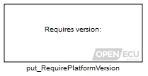
Restrict the versions of OpenECU platform that a model can be build against. This block can restrict the platform to a specific version, before or after a specific version, or to be between two versions.
More than one put_RequirePlatformVersion block may be added to a model to refine the restriction conditions.
If there are no put_RequirePlatformVersion blocks in a model, the model may be built against any version of platform (whether the build completes successfully will depend on which version of the platform the model was created with — e.g., a model created with features from a newer version of the platform may not build using an older version of the platform).
Note
In order for this block to function fully, the model postloadfcn property must be set according to the section Model pre-load and post-load hooks.
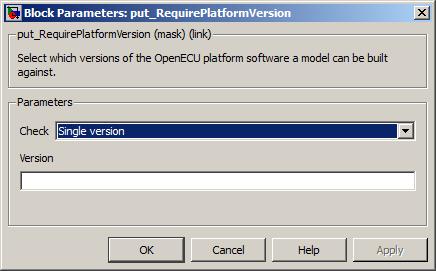
A drop-down of methods for restricting the version of platform to use when building.
Value type: List Calibratable: No The literal text of the version number (e.g.,
1.5.0) that the platform must equal in order to be able to build the model. Only available when the Check parameter is set to Single version.Value type: Text Calibratable: No The literal text of the version number (e.g.,
1.5.0) that the platform come before (not inclusive) in order to be able to build the model. Only available when the Check parameter is set to Before version.Value type: Text Calibratable: No The literal text of the version number (e.g.,
1.5.0) that the platform come after (not inclusive) in order to be able to build the model. Only available when the Check parameter is set to After version.Value type: Text Calibratable: No The literal text of the version number (e.g.,
1.5.0) that the platform come before (inclusive) in order to be able to build the model. Only available when the Check parameter is set to Range of versions.Value type: Text Calibratable: No The literal text of the version number (e.g.,
1.5.0) that the platform come after (inclusive) in order to be able to build the model. Only available when the Check parameter is set to Range of versions.Value type: Text Calibratable: No
Turn on Simulink's sample time colours.
None (Main library). (See Section 1.3, “Licensed Features”.)

A utility block to turn on Simulink's sample time colouring. Double click on the block to turn on sample time colours.
The SENT input block (Single Edge Nibble Transmission) decodes a SENT sensor's transmission pulses according to SAE J2716 Jan 2010, making available the sensor's status and data information.
None (Main library). (See Section 1.3, “Licensed Features”.)
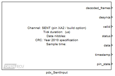
The SENT input block decodes a sensor's transmission pulses according to SAE J2716 Jan 2010, making available the sensor's status and data information. SAE J2716 describes SENT as:
The Single Edge Nibble Transmission encoding scheme (SENT) is intended for use in applications where high resolution sensor data needs to be communicated from a sensor to an Engine Control Unit (ECU). It is intended as a replacement for the lower resolution methods of 10 bit A/D converters and PWM and as a simpler low cost alternative to CAN or LIN. The implementation assumes that the sensor is a smart sensor containing a microprocessor or dedicated logic device (ASIC) to create the signal.
SENT is a unidirectional communications scheme from sensor (transmitting) device to controller (receiving) device which does not include a coordination signal from the controller/receiving device. The sensor signal is transmitted as a series of pulses with data encoded as falling to falling edge periods.
The SENT input block:
- decodes the SENT transmission into status and fast data nibbles;
- stores the last received, decoded and verified status and data nibbles;
- allows for a transmitter clock tick variance of ± 25% for the calibration and synchronisation pulse;
- allows for a transmitter clock tick between [3, 90] microseconds;
- allows for an optional pause pulse between transmissions;
- uses the calibration and sychronisation pulse to ratiometrically adjust the status, data and CRC pulses;
- verifies the frame size (checks the expected number of nibbles, or frame edges);
- verifies the frame CRC, either the 2008 or 2010 version;
- verifies that successive calibration pulses differ by no more than ± 1.5625%.
For short or enhanced serial message reception over 16 or 18 consecutive SENT frames, see the pdx_SentSerialInput block.
Available when Provide simulation input? is ticked. The value of this inport is copied to the corresponding outport during model simulation.
Value type: Integer Available when Provide simulation input? is ticked. The value of this inport is copied to the corresponding outport during model simulation.
Value type: Integer Available when Provide simulation input? is ticked. The value of this inport is copied to the corresponding outport during model simulation.
Value type: Integer Available when Provide simulation input? is ticked. The value of this inport is copied to the corresponding outport during model simulation.
Value type: Integer Available when Provide simulation input? is ticked. The value of this inport is copied to the corresponding outport during model simulation.
Value type: Integer Available when Provide simulation input? is ticked. The value of this inport is copied to the corresponding outport during model simulation.
Value type: Integer Available when Provide simulation input? is ticked. The value of this inport is copied to the corresponding outport during model simulation.
Value type: Integer
A counter incremented for each frame that is successfully received, decoded and verified.
Range: [0, inf] frames, modulo 256
Value type: Integer A counter incremented for each loss of synchronisation with the SENT sensor pulse stream. Loss of synchronisation occurs when the block pulse decoder has not seen a valid pulse for more than 125% of a calibration pulse duration (where a calibration pulse is 56 SENT ticks, Tick length); or a calibration, status, nibble or CRC pulse is too short; or the frame CRC verification fails.
Range: [0, inf] frames, modulo 256
Value type: Integer 1 if at least one SENT frame has been successfully received, decoded and verified, 0 otherwise. If 1, then the status and data outports provide the status and data received from the last frame, and the timestamp outport provides the time when the frame was received.
Range: 0 or 1
Value type: Boolean The status nibble of the last SENT frame that was successfully received, decoded and verified. Set to zero when a SENT frame has not been successfully received.
Range: 0 or 1
Value type: Integer The data nibbles of the last SENT frame that was successfully received, decoded and verified. Set to zero when a SENT frame has not been successfully received. The data nibbles are packed into the integer right aligned.
Range: [0, 16777215] unitless
Value type: Integer A timestamp taken when the last SENT frame was fully received, decoded and verified. The timestamp increments in counts of 256, wrapping approximately every 4 seconds. The timestamp can be used by the application to determine whether the SENT sensor is transmitting data at the expected period.
Range: [0, inf] counts, modulo 4294967296
Value type: Integer 1 if the channel pin voltage is above the detection threshold, 0 otherwise. Can be used by the application for electrical diagnostics.
Range: 0 or 1
Value type: Boolean
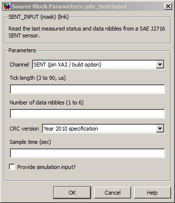
The channel pin for this SENT input.
Value type: List Calibratable: No The length of the SENT sensor's transmission clock tick connected to this channel.
Range: [3, 90] microseconds
Resolution: 0.1 microsecondsValue type: Real Calibratable: Yes, offline The number of data nibbles transmitted by the SENT sensor in each frame.
Range: [1, 6] nibbles
Value type: Integer Calibratable: Yes, offline The version of CRC algorithm used by the SENT sensor.
Value type: List Calibratable: Yes, offline The periodicity of the block execution.
Range: [0.001, 3600] seconds
Value type: Real Calibratable: No If selected then the block creates simulation inports for each of the outports.
Value type: Boolean Calibratable: No
The SENT serial input block (Single Edge Nibble Transmission) decodes a SENT sensor's transmission pulses according to SAE J2716 Jan 2010, making available the sensor's short or enhanced serial data.
None (Main library). (See Section 1.3, “Licensed Features”.)
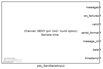
The SENT input block decodes a sensor's transmission pulses according to SAE J2716 Jan 2010, making available the sensor's short or enhanced serial data. See the pdx_SentInput block for a summary of SENT.
The SENT serial input block:
- decodes the status nibble from 16 or 18 consecutive SENT transmissions into message identification and data values;
- stores the last received, decoded and verified serial message;
- verifies the serial message CRC.
When using a pdx_SentSerialInput block, the application model must have a corresponding pdx_SentInput block to initialise the SENT channel.
Available when Provide simulation input? is ticked. The value of this inport is copied to the corresponding outport during model simulation.
Value type: Integer Available when Provide simulation input? is ticked. The value of this inport is copied to the corresponding outport during model simulation.
Value type: Integer Available when Provide simulation input? is ticked. The value of this inport is copied to the corresponding outport during model simulation.
Value type: Integer Available when Provide simulation input? is ticked. The value of this inport is copied to the corresponding outport during model simulation.
Value type: Integer Available when Provide simulation input? is ticked. The value of this inport is copied to the corresponding outport during model simulation.
Value type: Integer Available when Provide simulation input? is ticked. The value of this inport is copied to the corresponding outport during model simulation.
Value type: Integer Available when Provide simulation input? is ticked. The value of this inport is copied to the corresponding outport during model simulation.
Value type: Integer
A counter incremented for each serial message that is successfully received, decoded and verified.
Range: [0, inf] messages, modulo 256
Value type: Integer A counter incremented for each serial message that is received but that fails a CRC verification.
Range: [0, inf] messages, modulo 256
Value type: Integer Set to one if at least one serial message has been successfully received, decoded and verified, set to zero otherwise. If set to one, then the serial_formatpdxf_serial_format, message_id and data outports provide information about the last successfully received, decoded and verified message, and the timestamp outport provides the time when the message was received.
Range: 0 or 1
Value type: Integer The detected serial format of the last successfully received, decoded and verified serial message. Set to zero when a serial message has not been received.
Outport value Description 0 Identifies a short serial message, with a 4-bit message identifier and 8-bit data 1 Identifies an enhanced format 1 serial message, with a 8-bit message identifier and 12-bit data 2 Identifies an enhanced format 2 serial message, with a 4-bit message identifier and 16-bit data Value type: Integer The value of the message identifier of the last successfully received, decoded and verified serial message. Set to zero when a serial message has not yet been received.
Range: [0, 15] for short serial and enhanced serial format 2
Range: [0, 255] for enhanced serial format 1Value type: Integer The data nibbles of the last successfully received, decoded and verified serial message. Set to zero when a serial message has not yet been received.
Range: [0, 255] for short serial
Range: [0, 8192] for enhanced format 1
Range: [0, 65535] for enhanced format 2Value type: Integer A timestamp is taken when the last SENT message was fully received, decoded and verified. The timestamp increments in counts of 256, wrapping approximately every 4 seconds. The timestamp can be used by the application to determine whether the SENT sensor is transmitting data at the expected period.
Range: [0, inf] counts, modulo 4294967296
Value type: Integer
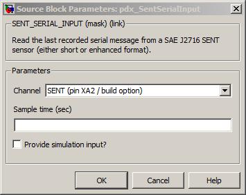
The channel pin for this SENT input.
Value type: List Calibratable: No The periodicity of the block execution.
Range: [0.001, 3600] seconds
Value type: Real Calibratable: No If selected then the block creates simulation inports for each of the outports.
Value type: Boolean Calibratable: No
Determine discontinuities in CAN message reception.
None (Main library). (See Section 1.3, “Licensed Features”.)
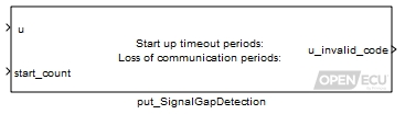
Determine whether the application:
is receiving a CAN message regularly (code 8); or
has yet to receive a CAN message (code 5); or
has not received a CAN message within the required start-up period (code 6); or
has stopped receiving the CAN message (code 7).
The block will start monitoring the status of inport u (whether a CAN message was received this model iteration or not) when the inport start_count is 1. For as long inport u is zero (no message received), the block will output code 5.
If the block observes that it has not received a single CAN message within the required module start-up period, the block will output code 6.
If the application has received at least a single CAN message within the required start-up period, but has then subsequently not received a new message for the pre-defined consecutive number of missed message periods, the block will output code 7.
For as long as the block is receiving CAN messages, the block will output code 8.
These output codes can be fed into the Section 6.1.103, “Signal validate (put_SignalValidate)” block to provide further fault detection.
Result of monitoring when the CAN message was received over time (inport u). See the table in the notes section for a complete list of the codes.
Range: [5, 8]
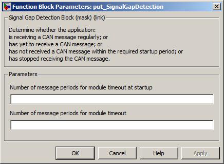
Number of message periods for module timeout at start-up
The number of message periods the block will wait after inport start_count has been set to 1, before reporting that it has not received a CAN message within this required period.
Range: [0, 255] periods
Number of message periods for module timeout
The number of message periods the block will wait, with inport u set to 0, before reporting that it has stopped receiving the CAN message.
Range: [0, 255] periods
The possible error codes (see also Table 6.8, “CAN signal validate error codes.”) are enumerated as:
Table 6.6. CAN signal gap error codes
| Invalid code | Description |
|---|---|
| 5 | The application has yet to receive the first CAN message (of a particular ID). |
| 6 | The application has not received a single CAN message (of a particular ID) within the defined start-up timeout period. |
| 7 | The application has received at least one message (of a particular ID) within the start-up timeout period, but has then subsequently not received a new message for a pre-defined number of message periods. |
| 8 | The put_SignalGapDetection block is receiving the CAN message within timeout periods. |
Prepare signals for CAN transmission.
None (Main library). (See Section 1.3, “Licensed Features”.)
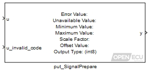
The signal prepare block converts from engineering value to integer form. The input value is checked against minimum and maximum parameters and clipping may occur when the result is copied into one of the possible integer data types of the output port.
It is common to find a CAN specification that designates values for CAN signals as in error or unavailable. Although not always the case, typically the highest values are used (e.g., in an unsigned 8 bit quantity that can range from 0 to 255, typically 254 and 255 signify that the signal is unavailable or in error). This block directly supports this concept.
Minimum and maximum limits (in engineering units) are also defined for each CAN signal, and an engineering value outside this range is set to a value which indicates error to the receiving CAN node. This block directly supports checking for out of range engineering values.
And while many quantities are transmitted in integer format that corresponds to the value in engineering units, many other fields have scale and offset values. This block directly supports converting the engineering value to a scaled integer value as:
can_signal_value y = (u - Offset value) / Scale factor
Value to convert from the application. The blocks accepts a data type of
uint8,int32andreal_T.Defines the validity of the input u. See Table 6.7, “CAN signal prepare invalid codes.” for a complete list of codes.
Range: [0, 8]
The value of u after being prepared for CAN transmission.
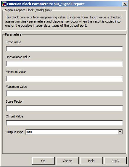
The value which is to be output on y if the inport u_invalid_code is equal to 1.
Range: [-2147483647, 2147483647]
The value which is to be output on y if the inport u_invalid_code is equal to 2, 5, 6, 7 or 8.
Range: [-2147483647, 2147483647]
The smallest value of u that is valid. The data type of this parameter is the same as the input u.
The largest value of u that is valid, The data type of this parameter is the same as the input u.
Conversion factor applied to u to convert it from engineering units to an integer form. A value of 1 should be used if no scaling is required.
Offset factor applied to u to convert it from engineering units to an integer form. The data type is in engineering units. A value of 0 should be used if there is no offset.
A drop down of possible types for inport u.
The possible error codes are enumerated as:
Table 6.7. CAN signal prepare invalid codes.
Error code Description 0, 3, 4 The block implements both conversion of the input engineering value to a scaled integer and clipping of the result, according to mask parameters setting. 1 The output value is forced to be equal to the mask error value. 2 or >4 The output value is forced to be equal to the mask unavailable value.
Validate and scale received CAN signal values.
None (Main library). (See Section 1.3, “Licensed Features”.)
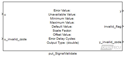
The signal validate block performs validation checks on a supplied input value (usually from a received CAN message). It checks for the input data being unavailable or in error, applies a linear transfer function, performs clipping, then casts the output to a user selected type.
It is common to find a CAN specification that designates values for CAN signals as in error or unavailable. Although not always the case, typically the highest values are used (e.g., in an unsigned 8 bit quantity that can range from 0 to 255, typically 254 and 255 signify that the signal is unavailable or in error). This block directly supports this concept.
Minimum and maximum limits (in engineering units) are also defined for each CAN signal, and received data outside those limits typically indicates an error (in transmitting module behaviour, or CAN communications). This block directly supports checking for out of range engineering values.
And while many quantities are transmitted in integer format that corresponds to the value in engineering units, many other fields have scale and offset values. This block directly supports converting the scaled integer value to an engineering value as:
engineering_value = (Scale factor * u) + Offset value
When an error is detected, if the block has previously output a valid value, it will continue to output the previous valid value while the error condition persists for a number of delayed cycles, after which, if the error persists, the default value is output.
The raw input value requiring validation.
A code that defines the status of the inport u. The block acts on an error code of 5, 6, 7, or 8 (see Table 6.8, “CAN signal validate error codes.”).
Range: [0, 8]
The clean output value after validation.
0 if the outport y_invalid_code is 0; 1 otherwise.
Range: 0 or 1
A value indicating the manner in which the input is invalid (see below for a table of error codes).
Range: [0, 8]
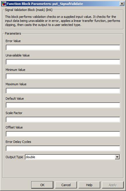
The value which indicates the input is in error. It is internally converted to
int32data type.Range: [-2147483647, 2147483647]
The value which indicates the input is unavailable. It is internally converted to
int32data type.Range: [-2147483647, 2147483647]
The smallest post-scaling value that is valid.
The largest post-scaling value that is valid.
The value to be substituted if necessary.
Conversion factor from integer to engineering units. A value of 1 should be used if no scaling is required.
Offset value to convert from integer to engineering units, in engineering units. A value of 0 should be used if no offset is required.
An integer number of block executions; the number of cycles before any error condition is output. May be zero, in which case error conditions are output immediately the block executes.
Range: [0, 65535]
A drop down of possible types for outport y.
The possible error codes are enumerated as:
Table 6.8. CAN signal validate error codes.
u_invalid_code y_invalid_code Description 8 0 The block implements both conversion of the input scaled integer value to an engineering value and clipping of the result, according to the mask parameters setting. 8 4 The block implements conversion of the input scaled integer value to an engineering value. The output has been clipped to the maximum value detailed in the block mask. 8 3 The block implements conversion of the input scaled integer value to an engineering value. The output has been clipped to the minimum value detailed in the block mask. 8 2 The output value is set to mask default value because the input value is equal to mask unavailable value. 8 1 The output value is set to mask default value because the input value is equal to mask error value. 5, 6, 7 equal to u_invalid_code The output value is set to mask default value because of the input invalid code. <5 or >8 2 The output value is set to mask default value because of the input invalid code.
Set the outport slew_fault if the rate of change of inport u is too great.
None (Main library). (See Section 1.3, “Licensed Features”.)
Compares the value of inport u between the current and previous model iterations and determines if the absolute difference exceeds the slew rate limit.
Set to 1 if the absolute difference between inport u at this model iteration and the previous model iterate is greater than the parameter Absolute raw slew rate limit, 0 otherwise. On the first model iteration, the block outputs 0.
Range: 0 or 1
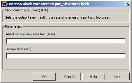
Interface to read the number of SPI transmit errors on a given device since initialisation.
None (Main library). (See Section 1.3, “Licensed Features”.)

Certain SPI devices support the ability to validate their communication with the main processor. If a fault occurs in the communication, the platform will track the error. This block allows the number of detected errors to be reported to the application.
Only used under simulation when the parameter Provide simulation input? is ticked. The outport count is written using the value of this inport.
Range: [0, 255] counts.
Value type: Real Calibratable: No
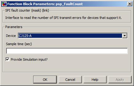
The SPI device for which to read the fault count.
Value type: List Calibratable: No The periodicity of the block execution.
Range: [0.001, 3600] seconds
Value type: Real Calibratable: No Tick to enable inport sim_count.
Value type: Boolean Calibratable: No
Get the maximum number of bytes used by the stack since power on (or reset).
None (Main library). (See Section 1.3, “Licensed Features”.)
Gets the number of bytes used by the application model and platform library since the ECU was last powered on (or reset). The stack is shared area of RAM used to store temporary information, such as calculations and function call parameters.
The total stack size allocated to the application model and platform library can be adjusted through the RTW options, see System stack size. It is important to allocate sufficient stack space for the worst case function call tree through the application and platform code otherwise the ECU may not behave as expected. While developing a model, keep a track of the stack size used and, as the usage grows, grow the system stack size appropriately.
Note
The ECUs are configured by the platform software to reset when the stack overflows its allocation. The reset prevents the ECU from behaving unexpectedly.
When using RTW as the model auto-coder, be aware that RTW has two ways of allocating model data.
RTW can statically allocate the data, which means that the model data is allocated to a fixed address in memory and not to the stack. This form of allocation is preferred because at run time the stack usage will be low, and if the model becomes too large for the ECU's memory, the model will fail to build completely.
Unselect the RTW Enable local block outputs option to have RTW statically allocate model data.
RTW can dynamically allocate the data to the stack. This means that the stack use can vary significantly at run time and the system stack size will need to be larger. This form of allocation is not preferred because to guarantee that the stack will not overflow will require detailed analysis of the RTW generated code.
Select the RTW Enable local block outputs option to have RTW dynamically allocate model data to the stack.
Only used under simulation and when the parameter Provide simulation inputs is ticked. The outport used_bytes is set to the value of this inport for simulation purposes.
Range: 0 to system stack size specified in System stack size.
The number of used bytes from the system stack size since the ECU was powered on (or reset). Under simulation, if the Provide simulation inputs parameter isn't ticked, the outport is set to the minimum of its range.
Range: 0 to system stack size specified in System stack size.
The periodicity of the block execution.
Range: [0.001, 3600] seconds
Value type: Real Calibratable: No Tick to enable inport sim_used_bytes.
Pulse two output channel pins at a variable frequency and variable duty cycle. The second output channel is synchronised to the first.
None (Main library). (See Section 1.3, “Licensed Features”.)
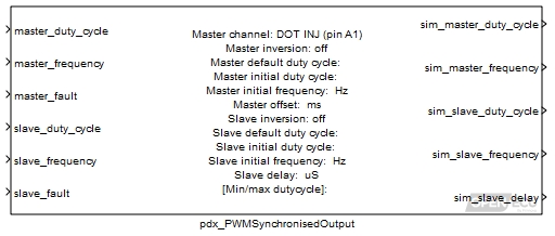
The synchronised PWM output block causes two channel output pins to oscillate with independent frequency and duty cycle. The duty cycle is the High time divided by the Cycle time for a given channel.
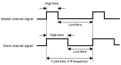
The slave channel is generated relative to the master channel pulse (in this instance, both the master and slave channels are generated with the same frequency).
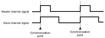
The slave pulse can be delayed relative to the master pulse by setting the parameter Slave delay to a non-zero value.
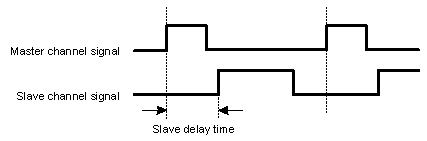
In all cases, only one pulse per cycle is generated by both the master and slave channels. For instance, if the frequency of the slave channel was twice that of the master channel, only one pulse would be generated by the slave channel.
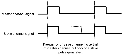
The Master channel output (and thus the slave) can be offset from other PWM channels of the same frequency. The Master offset parameter is used to delay the start of the PWM cycle, so that the PWM pulse will not occur at the same time as other PWM signals of the same frequency.
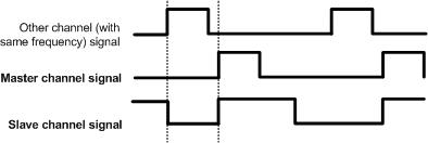
This block calculates the master output duty cycle as:
output master duty cycle = Minimum duty cycle + (Maximum duty cycle - Minimum duty cycle) * master_duty_cycle
and the slave output duty cycle as:
output slave duty cycle = Minimum duty cycle + (Maximum duty cycle - Minimum duty cycle) * slave_duty_cycle
For a given channel, if the output duty cycle is 0, the output channel state is set low and does not oscillate. If the output duty cycle is 1, the output channel state is set high and does not oscillate.
If the inport master_fault input is non-zero, then the output master duty cycle is set to the mask parameter Master default duty cycle. Similarly for the output slave duty cycle.
Ratio of the high time to the signal cycle time for the master channel.
Range: [0, 1] duty-cycle
Frequency of the master channel signal.
Range: [1, 10000] Hz (for M250, M460 targets)
Set to 1 to force the block to use the default master frequency and master duty cycle for the master channel, 0 otherwise.
Range: 0 or 1
Ratio of the high time to the signal cycle time for the slave channel.
Range: [0, 1] duty-cycle
Frequency of the slave channel signal.
Range: [1, 10000] Hz (for M250, M460 targets)
Set to 1 to force the block to use the default slave frequency and slave duty cycle for the slave channel, 0 otherwise.
Range: 0 or 1
Only used in simulation. this outport is set to the calculated duty cycle for the master channel.
Range: [0, 1] duty-cycle
Only used in simulation. this outport is set to the calculated frequency for the master channel.
Range: [1, 10000] Hz (for M250, M460 targets)
Only used in simulation. this outport is set to the calculated duty cycle for the slave channel.
Range: [0, 1] duty-cycle
Only used in simulation. this outport is set to the calculated frequency for the slave channel.
Range: [1, 10000] Hz (for M250, M460 targets)
Only used in simulation. this outport is set to the calculated frequency for the slave channel.
Range: [0, 1000000] microseconds
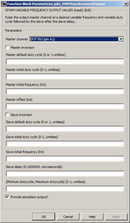
The master channel for this block. The slave channel is automatically assigned.
If selected, the final master duty cycle is set to 1 minus the output master duty cycle, otherwise the final master duty cycle is the same as the output master duty cycle.
This is the final duty cycle of the channel when inport master_fault is set. The duty cycle is mapped directly to the output channel and is not inverted by parameter Master inversion.
Range: 0 or 1 duty-cycle
The duty cycle of the channel signal before the block has first been executed. This duty cycle is inverted if the mask parameter Master inversion is set to 1.
Range: [0, 1] duty-cycle
The frequency of the channel signal before the block first iterates.
Range: [1, 10000] Hz (for M250, M460 targets)
The offset of the master (and hence the slave) channel output.
Range: Target dependent
Target Range M110 Not supported M220 Not supported M221 Not supported M250 [0, 2000] ms M460 [0, 2000] ms M461 Not supported M670 Not supported Value type: Real Calibratable: No If selected, the final slave duty cycle is set to 1 minus the output slave duty cycle, otherwise the final slave duty cycle is the same as the output slave duty cycle.
This is the final duty cycle of the channel when inport slave_fault is set. The duty cycle is mapped directly to the output channel and is not inverted by parameter Slave inversion.
Range: 0 or 1 duty-cycle
The duty cycle of the channel signal before the block has first been executed. This duty cycle is inverted if the mask parameter Slave inversion is set to 1.
Range: [0, 1] duty-cycle
The frequency of the channel signal before the block first iterates.
Range: [1, 10000] Hz (for M250, M460 targets)
The time delay between synchronisation of the master and slave channel. The slave pulse is started Slave delay microseconds after the master pulse starts.
Range: [0, 1000000] microseconds
Must be in the range 0 to (Maximum duty cycle - 0.1).
Range: [0, 0.9] duty-cycle
Must be in the range (Minimum duty cycle + 0.1) to 1.0.
Range: [0.1, 1] duty-cycle
Tick to enable outports sim_master_duty_cycle, sim_master_frequency, sim_slave_duty_cycle, sim_slave_frequency and sim_slave_delay.
Value type: Boolean Calibratable: No
If the pulse for the slave channel extends through the synchronisation point, then the master and slave channel signals become undefined. Most likely is that the master channel continues to generate a PWM signal and the slave channel goes low, but this is not guaranteed under all conditions.
To avoid an inconsistent update to the output, the low-lying driver (based on code from the silicon manufacturer) buffers new parameters before applying them. This results in a delay of two or three PWM cycles between the model updating the frequency or duty cycle and the effect being seen in the output waveform.
Get the last measured or maximum duration for a given model rate (task).
None (Main library). (See Section 1.3, “Licensed Features”.)
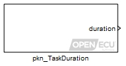
Each rate in a model is represented by a task. A task contains all the functionality to iterate that model rate. Simulink has a specific scheme for executing each task to simulate the model on the host PC, or to run the model on a target ECU. While arbitrarily large models can be run on the host PC, where the model is not run in real time, there is a limit to the size of model that can be executed on the target ECU. The psc_TaskDuration block provides feedback on how long each task takes to run and can be used to indicate whether all tasks run in real time or not.
The task duration excludes the time taken for other tasks to run and includes the time taken during platform interrupts. For instance, in a model which has a 5 millisecond and a 10 millisecond rate, the task duration measurement of the 10 millisecond task will not include any time taken up by an interrupting 5 millisecond task. But, in the same time frame, if the platform handled some interrupts for CAN messaging and angular functionality, then the time taken to service the interrupts is included.
Together with the psc_CpuLoading block, the psc_TaskDuration block can provide an indication of where the majority of the processing to run the model takes place, useful when attempting to optimise the model. It is useful to record the output of both these blocks across the lifetime of the model development — a graph of these values against time will quickly show if the model will become too large for the ECU as development progresses.
Only used under simulation and when the parameter Provide simulation inputs is ticked. The outport duration is set to the value of this inport for simulation purposes.
Range: [0, 4294967295] microseconds
The last measured duration of the model rate task, or the maximum duration seen for that task since the ECU was powered on (or reset). Under simulation, if the Provide simulation inputs parameter isn't ticked, the outport is set to the minimum of its range.
Range: Target dependent
Target Range M110 [0 53687091] microseconds M220 [0 53687091] microseconds M221 [0 53687091] microseconds M250 [0 53687091] microseconds M460 [0 53687091] microseconds M461 [0 53687091] microseconds M670 [0 16268815] microseconds
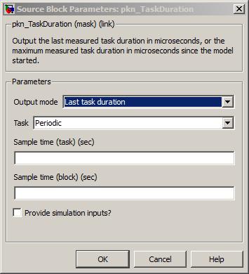
Whether the outport duration is set to the last measured task duration or the maximum task duration seen since the ECU was powered on (or reset).
The periodicity of the model rate to measure.
Range: [0.001, 3600] seconds
In order to provide accurate task monitoring, it is recommended that the sample time be configured to be no greater than the maximum amount of time that can be represented by outport duration
The periodicity of the block. The task and block sample time allow the model rate task measurement to occur independently from the task itself.
Range: [0.001, 3600] seconds
Tick to enable inport sim_duration.
Get the count of overruns for a given model rate (periodic task).
None (Main library). (See Section 1.3, “Licensed Features”.)
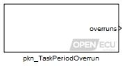
Each rate in a model is represented by a task. A task contains all the functionality to iterate that model rate. Simulink has a specific scheme for executing each task to simulate the model on the host PC, or to run the model on a target ECU. While arbitrarily large models can be run on the host PC, where the model is not run in real time, there is a limit to the size of model that can be executed on the target ECU in real time. The pkn_TaskPeriodOverrun block provides feedback on how many times a model rate (periodic) task has overrun its rate.
For example, if a model contains a 5 millisecond rate then the pkn_TaskPeriodOverrun block counts the number of times the 5 millisecond model rate task becomes ready to run when the 5 millisecond task is already running.
A model rate task may overrun its period for a number of reasons:
The quantity and type of blocks required to execute every period is too much for the target ECU to achieve.
A higher priority model rate task or tasks (those with shorter periods) uses up processor time that the lower priority model rate tasks require to complete within their period.
Together with the psc_CpuLoading block, and the pkn_TaskDuration block, the pkn_TaskPeriodOverrun block can provide an indication of where the majority of the model processing takes place, useful when attempting to optimise the model. It is useful to record the output of these blocks across the lifetime of the model development — a graph of these values against time will help to indicate if the model will become too large for the ECU as development progresses.
Only used under simulation and when the parameter Provide simulation inputs is ticked. The outport overruns is set to the value of this inport for simulation purposes.
Range: [0, 255] counts
The saturated counts of periodic overruns for the model rate task since the ECU was powered on (or reset). Under simulation, if the Provide simulation inputs parameter isn't ticked, the outport is set to the minimum of its range.
Range: [0, 255] counts
Value type: integer
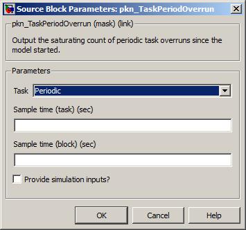
The periodicity of the model rate to measure.
Range: [0.001, 3600] seconds
Value type: float Calibratable: No The periodicity of the block. The task and block sample time allow the model rate task measurement to occur independently from the task itself.
Range: [0.001, 3600] seconds
Value type: float Calibratable: No Tick to enable inport sim_overruns.
Value type: boolean
Import TargetLink subsystem production code.

This block allows for easy import of production code from a subsystem developed in TargetLink. The TargetLink model name, subsystem name, and input/output ports are specified in the block interface. One button causes the block to configure itself to have the specified interface. Another button launches the TargetLink code generator to generate production code for the TargetLink subsystem, imports the production code into the model at the block location, and imports the TargetLink data dictionary entries into the Simulink data dictionary.
Currently, TargetLink version 4.4 (2018-B) has been tested and is supported. Newer TargetLink versions are expected to be compatible, but have not been fully tested.

The TargetLink model file, including path.
Press the "Browse..." button to browse for the model file. If the browse button is used, you will be prompted to select which subsystem from the TargetLink model file that you wish to import. All mask parameters will be automatically populated from the selected TargetLink subsystem.
Value type: String Calibratable: No The name of the TargetLink subsystem in the TargetLink model that you wish to import.
Value type: String Calibratable: No The names of the input ports for the block interface, separated by commas.
Value type: String Calibratable: No The names of the output ports for the block interface, separated by commas.
Value type: String Calibratable: No Clicking this button will update the interface of this block. Input ports will be created according to the "Input port names" parameter, and output ports will be created according to the "Output port names" parameter. Note that clicking this button will disconnect the block from the rest of the model as the block is re-drawn.
Value type: Boolean Calibratable: No Clicking this button will import TargetLink production code into the model at the current block location. The following actions occur:
The TargetLink code generator is launched to produce production code from the TargetLink subsystem.
An s-function generated by TargetLink is placed within the current block.
The model configuration is updated to include the TargetLink production code as "custom code".
Target Language Compiler (TLC) code is generated for the current block to call the TargetLink production code.
All data entries in the TargetLink data dictionary associated with the selected TargetLink model will be imported into the Simulink data dictionary.
Value type: Boolean Calibratable: No
TargetLink integration has the following restrictions:
The TargetLink subsystem in the TargetLink model must have all inports and outports configured to be function reference arguments (Class: FCN_REF_ARG in the TargetLink dialog).
The OpenECU model must be configured to use the Simulink data dictionary. This is because the text based data dictionary does not support fixed point scaling and offset.
The model must be configured to disable the OpenECU naming convention. See the following image.
The model must be configured to use OpenECU ASAP2 generation (Configuration Parameters/ Interface/ASAP2 interface must NOT be ticked). This is because Simulink's ASAP2 generator cannot generate ASAP2 entries for variables that originate in custom code. See the following image.
Only scalar and array inports and outports are supported. TargetLink bus ports are not supported at the current time.


Output the time since the model started (absolute), or output the time since the last time the block executed (relative).
None (Main library). (See Section 1.3, “Licensed Features”.)
Output the current time (absolute), or output the time since the last time the block executed (relative). Time is tracked in two ways: for host simulation — using Simulink's task timing; and for target execution — using the ECU's operating system timers.
When run under simulation, this block has the same behaviour as the Simulink Time block, see Section 6.1.112, “Time (Simulink) (ptm_SimulinkTime)”.
When run on target, this block reads the time from the ECU's operating system. The ECU's operating system utilises a high resolution timer to provide microsecond, millisecond and second results, any of which can be selected as the block output using the drop-down option. When the block is iterated, the time outport is the latest reading from the high resolution timer.
The ptm_RealTime block can be configured to provide an absolute time or a relative time. The absolute time is the time at which the block is iterated since the start of the model (after power on, or reset). The relative time is time since the block was last iterated, or if the block has never iterated before, the time since the start of the model.
To understand the absolute time configuration, consider a simple model with two model rates, 5ms and 10ms. The 5ms model rate contains a ptm_RealTime block configured for absolute time, and to work in microseconds. The block is iterated at times A, C and D.
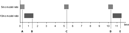
And to understand the relative time configuration, consider the same model where the 10ms model rate contains a ptm_RealTime block configured for relative time. The block is iterated at times B and E.
At time B, the ptm_RealTime block sets time outport value to around 1330 microseconds (the time since the model started as there has been no iteration of the block prior to time B).
At time E, the ptm_RealTime block sets time outport value to around 10000 microseconds, being the difference between time E and B. The precise value will vary depending on the influence of higher-priority tasks and interrupt work.
The description above uses the term “around x milliseconds” because of task jitter. Task jitter occurs when the length of time a task takes to complete varies each time the task runs. As an example, consider a task that has some logic implemented by the auto-coder as an if-else statement. If in different iterations of the model task different parts of the if-else statement run, and if the processing which occurs for those parts differs, then each part will take a different amount of time to complete and the overall task duration will vary. If the ptm_RealTime block occurs after the if-else logic then the time output by the block will vary.
Warning
The type of outport time is an unsigned 32-bit integer, which limits the range of time this block can represent.
| Resolution | Maximum duration |
|---|---|
| Microseconds | approx. 71 minutes |
| Milliseconds | approx. 49 days |
| Seconds | approx. 136 years |
The value for both absolute and relative time are provided modulo 232. It is up to the application to take care of the wrap around caused by the modulo.
The current real-time taken from the ECU's operating system timer, as either an absolute time since the model started, or as a relative time since the last time the block was iterated (or the start of the model if the block has not been iterated before).
Range: [0, inf] modulo 232, seconds, milliseconds, or microseconds
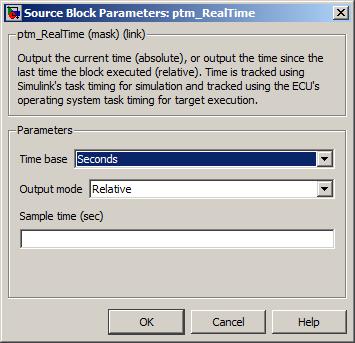
Output the time since the model started (absolute), or output the time since the last time the block executed (relative).
None (Main library). (See Section 1.3, “Licensed Features”.)
Output the current Simulink task time (absolute), or output the time since the last time the block executed (relative). Time is tracked using Simulink's task timers for both host simulation and target execution.
This block reads the time from the Simulink's task timers. Simulink task timers track the time each task should run at the resolution of the quickest model rate. For instance, if there were two model rates, 5ms and 10ms, then the resolution of the Simulink task timer for each model rate would be 5ms. The block converts these timers to microsecond, millisecond or second resolution, as required by parameter Time base. When the block is iterated, the time outport is the timer for the current model rate task.
The ptm_SimulinkTime block can be configured to provide an absolute time or a relative time. The absolute option is the Simulink task time at which the block is iterated since the start of the model (after power on, or reset). The relative option is the Simulink task time since the block was last iterated, or if the block has never iterated before, the Simulink task time since the start of the model.
To understand the absolute time configuration, consider a simple model with two model rates, 5ms and 10ms. The 5ms model rate contains a ptm_SimulinkTime block configured for absolute time. The block is iterated at times A, C and D.
At time A, the ptm_SimulinkTime block sets time outport value to 0 milliseconds (the time since the model started). Note that the time matches the start of the model rate task and not the current time. If the current time is required then see the ptm_RealTime block.
At time C, the ptm_SimulinkTime block sets time outport value to 5 milliseconds.
At time D, the ptm_SimulinkTime block sets time outport value to 10 milliseconds.
And to understand the relative time configuration, consider the same model where the 10ms model rate contains a ptm_SimulinkTime block configured for relative time. The block is iterated at times B and E.
In the last example at time B, the 10ms Simulink task timer is zero rather 0.5 milliseconds. The Simulink task timer is zero because Simulink would like to start both the 5ms and 10ms model rate tasks at the same time, time zero. Because the ECU's operating system runs the quickest rate task first, the 10ms model rate task starts after the 5ms model rate task has completed.
If the 10ms model rate task were to take longer and the 5ms model rate task ran more quickly, for example, every 2ms, then the task sequence over time looks different:
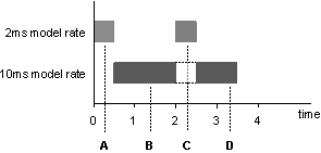
At time A, the ptm_SimulinkTime block sets time outport value to 0 milliseconds.
At time B, the ptm_SimulinkTime block sets time outport value to 0 milliseconds.
At time C, even though the 10ms task has not yet completed, the 2ms model rate task ran and Simulink updated timer for that task. The ptm_SimulinkTime block therefore sets time outport value to 2 milliseconds.
At time D, the 10ms model rate task has not yet completed and the Simulink task timer remains at zero. The ptm_SimulinkTime block therefore sets time outport value to 0 milliseconds.
Warning
The type of outport time is an unsigned 32-bit integer, which limits the range of time this block can represent.
| Resolution | Maximum duration |
|---|---|
| Microseconds | approx. 71 minutes |
| Milliseconds | approx. 49 days |
| Seconds | approx. 136 years |
The value for both absolute and relative time are provided modulo 232. It is up to the application to take care of the wrap around caused by the modulo.
Simulink may generate code to maintain its task timers using a type which cannot represent the full range of the outport time. In this case, the Simulink task timers may saturate rather than wrap around due to the modulo. Again, it is up to the application to address this condition.
For more information about Simulink's task timers see the MathWorks' documentation for RTW.
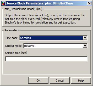
Update internal configuration of CJ125 devices.
None (Main library). (See Section 1.3, “Licensed Features”.)
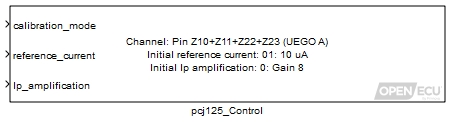
Interface to control behaviour of a UEGO sensor via CJ125 device.
The Platform provides this interface for ECUs containing Bosch CJ125 devices to uses the device to interact with external Bosch LSU 4.9 UEGO sensors. For further information on connecting to and using UEGO sensors, please see the ECU's technical specification.
This block is called periodically during an application task to set the internal configuration of the specified CJ125 device. The block should be called in a task with the desired rate at which the device should be reconfigured.
Set to 0 to put the CJ125 device in normal operation mode. Set to 1 to put the device in calibration mode. This will cause the UR and UA analogue inputs for the CJ125 to be set to their calibration values.
When calibration mode is enabled, UR, being the input indicating the temperature of the UEGO sensor, will indicate the UR measurement corresponding to the optimal UEGO sensor temperature. UA, being the input indicating the UEGO pump cell current, will be set to the value corresponding to a Lambda measurement of 1 when calibration mode enabled. See the ECU's technical specification for more details.
Range: [0, 1]
Value type: Integer Set to the enumeration of the desired reference current used by the device.
Range: [0, 15] respectively for the enumeration values: 0 uA, 10 uA, 20 uA, 30 uA, 40 uA, 50 uA, 60 uA, 70 uA, 80 uA, 90 uA, 100 uA, 110 uA, 120 uA, 130 uA, 140 uA, 150 uA
Value type: Integer Set to the enumeration value corresponding to the desired amplification of the pump current (Ip). Ip is calculated from the UA input and its value is dependent on the specified gain setting. See the ECU's technical specification for more details.
Range: [0, 1] respectively for the enumeration values: Gain 8, Gain 17
Value type: Integer
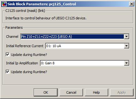
Which CJ125 device to control.
Value type: List Calibratable: No Initial value of the Reference Current.
Value type: List Calibratable: No If selected then inport reference_current is made available. Otherwise the Initial Reference Current value is used during runtime.
Value type: Boolean Calibratable: No Initial value of Ip Amplification.
Value type: List Calibratable: No If selected then inport Ip_amplification is made available. Otherwise the Initial Ip Amplification value is used during runtime.
Value type: Boolean Calibratable: No
Kick the processor watchdog to avoid reset.
None (Main library). (See Section 1.3, “Licensed Features”.)
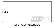
A watchdog is a timer that causes a processor reset when the timer exceeds a maximum duration. By kicking the watchdog on a periodic basis, the processor reset never occurs. A simple scheme to utilise the watchdog kicks the watchdog on a periodic basis. A more complex scheme might kick the watchdog only if the software appears to be performing the correct functionality (for instance, if two independent measurements of the same quantity show a large discrepancy).
The psc_KickWatchdog block causes the processor watchdog timer to clear thus avoiding a reset. Each ECU has a fixed watchdog duration.
| Target ECU | Watchdog duration | Maximum kick period |
|---|---|---|
|
M110, M220, M221,
M250, M460, M461 | [~419, ~838] milliseconds [a] | 200 milliseconds |
| M670 | [~508, ~1016] milliseconds [a] | 200 milliseconds |
[a] The range reflects the configuration of the processor's watchdog, which uses two time out periods before resetting the processor. | ||
If no psc_KickWatchdog block is present in the model then the watchdog will be kicked by the platform automatically at the maximum period for the target ECU.
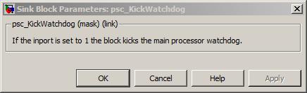
Specify the boost voltage setpoint for all output waveforms.
None (Main library). (See Section 1.3, “Licensed Features”.)

This block configures the boost voltage for all waveforms. The waveform must be setup using a prop_WaveformConfig block.
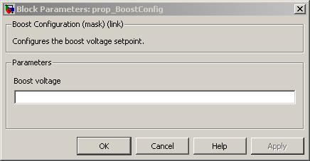
Specify the voltage, current and duration properties of a waveform.
None (Main library). (See Section 1.3, “Licensed Features”.)
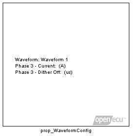
This block configures the properties of a waveform by setting the voltage, current and durations for up to three phases. An example of a possible waveform is shown in Figure 6.19, “Three stage, waveform”.
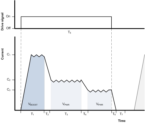
In the above diagram, T1 and T2 correspond to Phase 1, T3 and T4 correspond to Phase 2 and Phase 3 is the remaining portion of the waveform up to the entire pulse duration, T5. The Phase 1 on duration is set with the Phase 1 - Duration (us) paramter (T1) and the Phase 2 on duration is set with the Phase 2 - Duration (us) paramter (T3). The T5 duration is set with either a time-based or angular-based output block configured for the corresponding output pin.
The block allows either the boost supply or battery supply to be selected for the voltage during each Phase 1 and Phase 2. These options can be configured with the Phase 1 - Select Vboost and Phase 2 - Select Vboost parameters.
The current setpoint can be selected individually for each phase providing for a number of different possible combinations. Phase 1 and 2 are unique in that they can be configured to terminate when the current setpoint is reached with the Phase 1 - Switch at current and Phase 2 - Switch at current, parameters. When the waveform is configured in this manner, the Phase 1 - Duration (us) (T1) and/or Phase 2 - Duration (us) (T2) options are used as maximum duration timeouts. If the load current cannot be reached within the duration configured for the phase, the output will switch to the next phase. If the phase duration is set to zero, the phase is skipped. Phase 3 will continue for the remaining duration of the pulse (T5).
During each phase a dither off time can be configured individually per phase. (Phase 1 - Dither off duration (us), Phase 2 - Dither off duration (us), Phase 3 - Dither off duration (us)). When the current setpoint is reached during the phase, the output will turn off for the dither off time before turning back on, to regulate the current at the setpoint. This parameter can be used to increase or decrease the amount of dither around the current setpoint during each phase.
At the end of the phase before switching to the next phase, a phase switch off time can be configured to provide for a faster current decay rate between phases. During this time current is allowed to recirculate freely through the load, providing for a faster switch between two current setpoints. The Phase 1 switch off duration is set with the Phase 1 - Switch off duration (us) paramter (T2) and the Phase 2 switch off duration is set with the Phase 1 - Switch off duration (us) paramter (T4).
A prop_WaveformConfig block must be present in the model and specified for an output channel with a prop_WaveformSetChannel block for either boosted/non-boosted or overlapping/non-overlapping peak and hold outputs to operate.
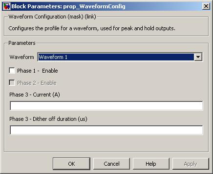
A drop down to identify the waveform to configure. The selection of waveform is dependent on the target ECU hardware selected in the put_Identification block.
Value type: List Calibratable: No Enables Phase 1 of the waveform. If this option is unchecked, the phase will be skipped.
Value type: Boolean Calibratable: No Enables the boost supply as the source of the high side during Phase 1 of the waveform. If this option is unchecked, the high side will be driven with battery voltage.
Value type: Boolean Calibratable: No Sets the duration of the driven (i.e. T1) period of Phase 1 of the waveform. If Phase 1 - Switch at current is unchecked the current will be regulated to value set by Phase 1 - Current (A). If Phase 1 - Switch at current is checked the duration is the maximum time to wait before switching to the next phase if the phase current has not been reached.
Range: [0, 3000] us (boosted) Range: [0, 10922.5] us (non-boosted)
Value type: Real Calibratable: Yes, offline Enables Phase 1 of the waveform to be terminated immediately upon reaching the current set by Phase 1 - Current (A). If this option is unchecked, the phase will be active for the entire duration set by Phase 1 - Duration (us).
Value type: Boolean Calibratable: No Sets the current level during the driven (i.e. T1) period of Phase 1 of the waveform.
Range: [0, 25] A (boosted) Range: [0, 16] A (non-boosted)
Value type: Real Calibratable: Yes, offline Phase 1 - Dither off duration (us)
Sets the duration of the off period after reaching the phase current during the driven period of Phase 1 (i.e. T1) of the waveform. The duration will affect the current dither during the phase. A larger value will allow the current to drop further, providing more dither.
Range: [10, 10922.5] us
Value type: Real Calibratable: Yes, offline Phase 1 - Switch off duration (us)
Sets the duration of the non-driven (i.e. T2) period of Phase 1 of the waveform. During this phase, both the high side and low side of the output are turned off allowing current to recirculate through the load to the Vboost supply, providing a faster current decay rate when switching phases. If no recirculation is required, the duration can be set to zero.
Range: [0, 10922.5] us
Value type: Real Calibratable: Yes, offline Enables Phase 2 of the waveform. If this option is unchecked, the phase will be skipped.
Value type: Boolean Calibratable: No Enables the boost supply as the source of the high side during Phase 2 of the waveform. If this option is unchecked, the high side will be driven with battery voltage.
Value type: Boolean Calibratable: No Sets the duration of the driven (i.e. T3) period of Phase 2 of the waveform. If Phase 2 - Switch at current is unchecked the current will be regulated to value set by Phase 2 - Current (A). If Phase 2 - Switch at current is checked the duration is the maximum time to wait before switching to the next phase if the phase current has not been reached.
Range: [0, 3000] us (boosted) Range: [0, 10922.5] us (non-boosted)
Value type: Real Calibratable: Yes, offline Enables Phase 2 of the waveform to be terminated immediately upon reaching the current set by Phase 2 - Current (A). If this option is unchecked, the phase will be active for the entire duration set by Phase 2 - Duration (us).
Value type: Boolean Calibratable: No Sets the current level during the driven (i.e. T3) period of Phase 2 of the waveform.
Range: [0, 25] A (boosted) Range: [0, 16] A (non-boosted)
Value type: Real Calibratable: Yes, offline Phase 2 - Dither off duration (us)
Sets the duration of the off period after reaching the phase current during the driven period of Phase 2 (i.e. T3) of the waveform. The duration will affect the current dither during the phase. A larger value will allow the current to drop further, providing more dither.
Range: [10, 10922.5] us
Value type: Real Calibratable: Yes, offline Phase 2 - Switch off duration (us)
Sets the duration of the non-driven (i.e. T3) period of Phase 2 of the waveform. During this phase, both the high side and low side of the output are turned off allowing current to recirculate through the load to the Vboost supply, providing a faster current decay rate when switching phases. If no recirculation is required, the duration can be set to zero.
Range: [0, 10922.5] us
Value type: Real Calibratable: Yes, offline Sets the current level during the driven (i.e. after T4) period of Phase 3 of the waveform.
Range: [0, 16] A
Value type: Real Calibratable: Yes, offline Phase 3 - Dither off duration (us)
Sets the duration of the off period after reaching the phase current during the driven period of Phase 3 (i.e. after T4) of the waveform. The duration will affect the current dither during the phase. A larger value will allow the current to drop further, providing more dither.
Range: [10, 10922.5] us
Value type: Real Calibratable: Yes, offline
Specify the waveform for a output channel.
None (Main library). (See Section 1.3, “Licensed Features”.)

This block configures the waveform to use for an output channel. The waveform must be setup using a prop_WaveformConfig block.
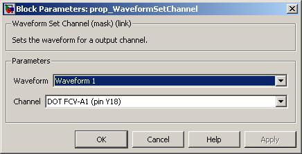
A drop down to identify the waveform to select. The selection of waveform is dependent on the target ECU hardware selected in the put_Identification block.
Value type: List Calibratable: No The channel to associate with the configured waveform.
Value type: List Calibratable: No
When an application is built, a number of ASAP2 entries are automatically generated. These entries reflect a number of application properties and run-time parameters which are useful to monitor during development and deployment.
The sections below give a complete list of automatically generated ASAP2 entries.
Note
When using PiSnoop be sure to load the ASAP2 (.a2l) file symbols to view these parameters. In many cases they are aliases for C variables with different names in the .elf file, and some have necessary scale factors applied in the ASAP2 attributes.
The boot software runs when the ECU is turned on. It conditions the ECU for running the reprogramming software or application software. The version and build date of this software is available through the following ASAP2 entries.
Table 6.9. Automatic ASAP2 entries for boot build information
| ASAP2 name | Description | Units |
|---|---|---|
| mpl_boot_ver_major | The boot software major version number. | - |
| mpl_boot_ver_minor | The boot software minor version number. | - |
| mpl_boot_ver_sub | The boot software sub-minor version number. | - |
| mpl_boot_build_day | The numerical day when the boot software was created. | days |
| mpl_boot_build_month | The numerical month when the boot software was created. | months |
| mpl_boot_build_year | The numerical year when the boot software was created. | years |
| mpl_boot_part_num_group | The Group ID numerical value of the boot software part number. | - |
| mpl_boot_part_num_letter | The Group Letter ASCII value of the boot software part number. | - |
| mpl_boot_part_num_id | The Part ID numerical value of the boot software part number. | - |
| mpl_boot_part_num_issue | The Issue numerical value of the boot software part number. | - |
Past and current boot code version numbering is given in Section 6.3, “OpenECU software versioning”.
The ECU's reprogramming mode is started as described in Section 4.5, “Programming an ECU”. The reprogramming code communicates using CCP (version 2.1) and provides a calibration tool with a mechanism to change the application software and/or calibration.
Table 6.10. Automatic ASAP2 entries for reprogramming build information (M220, M221, M250, M460, M461, M670)
| ASAP2 name | Description | Units |
|---|---|---|
| mpl_prg_ver_major | The reprogramming software major version number. | - |
| mpl_prg_ver_minor | The reprogramming software minor version number. | - |
| mpl_prg_ver_sub | The reprogramming software sub-minor version number. | - |
| mpl_prg_build_day | The numerical day when the reprogramming software was created. | days |
| mpl_prg_build_month | The numerical month when the reprogramming software was created. | months |
| mpl_prg_build_year | The numerical year when the reprogramming software was created. | years |
| mpl_prg_part_num_group | The Group ID numerical value of the reprogramming software part number. | - |
| mpl_prg_part_num_letter | The Group Letter ASCII value of the reprogramming software part number. | - |
| mpl_prg_part_num_id | The Part ID numerical value of the reprogramming software part number. | - |
| mpl_prg_part_num_issue | The Issue numerical value of the reprogramming software part number. | - |
Past and current boot code version numbering is given in Section 6.3, “OpenECU software versioning”.
The platform software creates an environment where by the application software can execute and access the target ECU hardware.
Table 6.11. Automatic ASAP2 entries for platform build information
| ASAP2 name | Description | Units |
|---|---|---|
| mpl_plat_ver_major | The platform software major version number. | - |
| mpl_plat_ver_minor | The platform software minor version number. | - |
| mpl_plat_ver_sub | The platform software sub-minor version number. | - |
| mpl_plat_build_day | The numerical day when the platform software was created. | days |
| mpl_plat_build_month | The numerical month when the platform software was created. | months |
| mpl_plat_build_year | The numerical year when the platform software was created. | years |
| mpls_plat_build_time | The date and time when the platform was created as a text string. | - |
| mpls_plat_copyright | The platform's copyright notice. | - |
| mpls_plat_target | The hardware target the application was built to be run on as a text string. | - |
| mpls_plat_version | The version of the platform the application was built against as a text string. | - |
| mpl_plat_part_num_group | The Group ID numerical value of the platform part number the application was build against. | - |
| mpl_plat_part_num_letter | The Group Letter ASCII value of the platform part number the application was build against. | - |
| mpl_plat_part_num_id | The Part ID numerical value of the platform part number the application was build against. | - |
| mpl_plat_part_num_issue | The Issue numerical value of the platform part number the application was build against. | - |
Past and current boot code version numbering is given in Section 6.3, “OpenECU software versioning”.
When the application is built, the automatically generated application code and the platform software are combined, and the result is the application software configured for the target ECU hardware.
The application name, description and copyright, as well as the time and date when the application was built, is available through ASAP2 entries. This information is useful when confirming what the ECU is actually executing.
Table 6.12. Automatic ASAP2 entries for application build information
| ASAP2 name | Description | Units |
|---|---|---|
| mpl_app_ver_major | The application software major version number. | - |
| mpl_app_ver_minor | The application software minor version number. | - |
| mpl_app_ver_sub | The application software sub-minor version number. | - |
| mpl_app_build_sec | The seconds when the application software was built. | seconds |
| mpl_app_build_min | The minute when the application software was built. | minutes |
| mpl_app_build_hour | The hour (in 24 hour format) when the application software was built. | hours |
| mpl_app_build_day | The numerical day when the application software was built. | days |
| mpl_app_build_month | The numerical month when the application software was built. | months |
| mpl_app_build_year | The numerical year when the application software was built. | years |
| mpls_app_build_time | The date and time when the application was built as a text string. | - |
| mpls_app_copyright | The copyright notice for the application. | - |
| mpls_app_description | The application description. | - |
| mpls_app_name | The name of the built application. | - |
| mpls_app_version | The application version number as a text string. | - |
Note
The time displayed at the end of a build in Simulink matches ASAP2 entries above. This can be useful when determining whether the correct version of the application was programmed into the ECU.
When the application is executing, the platform is maintaining a series of tasks that iterate the application at periodic rates (and possibly on an angular rate if engine functionality is required). These tasks take an amount of time to execute and the following ASAP2 entries record how long the last ran.
Table 6.13. Automatic ASAP2 entries for application rate task timing information
| ASAP2 name | Description | Units |
|---|---|---|
| mpl_tt_task_[xxx]ms | The duration of the last application iteration for the [xxx] model rate. | microseconds |
| mpl_tt_task_angular | The duration of the last TDC-firing triggered application iteration. | microseconds |
When the application is executing, the platform is maintaining a series of tasks that support the application. These tasks perform basic input and output support as well as general housekeeping. Each task takes some time to execute and the following entries record the last execution time of each.
Table 6.14. Automatic ASAP2 entries for auxiliary task timing information
| ASAP2 name | Description | Units |
|---|---|---|
| mpl_tt_pan_task | The duration of angular platform task. This task supports the angular application iteration. | microseconds |
| mpl_tt_pan_knock | The duration of angular knock support task. | microseconds |
| mpl_tt_pan_knock_ref | The duration of angular knock reference support task. | microseconds |
| mpl_tt_pcx_tcan_callback | The duration of the CAN receive and transmit (event) support task. | microseconds |
| mpl_tt_pcx_qemptier | The duration of the CAN receive and transmit (polled) support task. | microseconds |
| mpl_tt_pcx_qemptier_mcp2515 | The duration of the CAN receive and transmit (event) support task. | microseconds |
| mpl_tt_psp_receive | The duration of the serial input and output support task. | microseconds |
| mpl_tt_psc_watchdog | The duration of the watchdog support task. | microseconds |
| mpl_tt_pcp_client | The duration of the CCP support task. This task provides CCP support for the calibration tool. | microseconds |
| mpl_tt_ppp_client | The duration of the PixCal/tuning comms protocol task. This task provides support for tunable parameters via the PixCal calibration tool. | microseconds |
These entries support development by showing how long the software takes to run on the target hardware. As development progresses, new functionality can be compared to previous functionality to assess how much processing time is consumed.
The assessment can be made by noting how frequently the tasks run and how long they take, giving an estimated total consumption.
Table 6.15. Automatic ASAP2 entries for CPU loading information
| ASAP2 name | Description | Units |
|---|---|---|
| mpl_cpu_loaded | The amount of CPU used by the application and platform software in the last 50 milliseconds as a percentage. The CCP task may cause the loading to reach 100 percent under certain conditions but this is normal. The long running CCP task will not cause application iterations or other functionality to be delayed. | percent |
Some target ECU support loading measurement for processing devices other than the CPU. The eTPU device, or devices, are used for simple and complex I/O processing.
Table 6.16. Automatic ASAP2 entries for eTPU loading information
| ASAP2 name | Description | Units |
|---|---|---|
| mpl_etpu_a_loaded | The amount of eTPU (device A) used by the application and platform software in the last 50 milliseconds as a percentage. | percent |
| mpl_etpu_b_loaded | The amount of eTPU (device B) used by the application and platform software in the last 50 milliseconds as a percentage. | percent |
Although previous entries record how long the last execution took, it is useful to know the longest execution that has occurred since power up. There are ASAP2 entries to support this.
Table 6.17. Automatic ASAP2 entries for maximum application rate task timing information
| ASAP2 name | Description | Units |
|---|---|---|
| mpl_mtt_[name] | The largest value of the corresponding application duration ASAP2 variable seen since the last power up or reset. | microseconds |
| mpl_max_cpu_loaded | The largest value of mpl_cpu_loaded seen since the last power up or reset. | percent |
| mpl_max_etpu_a_loaded | The largest value of mpl_etpu_a_loaded seen since the last power up or reset. | percent |
| mpl_max_etpu_b_loaded | The largest value of mpl_etpu_b_loaded seen since the last power up or reset. | percent |
Note that the maximum task duration entries record the longest execution seen since power up and not the worst case execution time of the task. It could be that a task will take longer to run if given different stimuli. OpenECU does not support the direct derivation of worst case execution times.
There is also a seconds counter which is cleared to zero when the ECU is turned on or resets. The counter can be used to determine if the ECU is resetting on a regular or irregular basis.
Table 6.18. Automatic ASAP2 entries for run-time information
| ASAP2 name | Description | Units |
|---|---|---|
| mpl_run_time | A seconds counter of the time since power up; range [0, 4294967294]. | seconds |
Expected and unexpected resets are logged and counted. There are ASAP2 entries to report reset counts.
Table 6.19. Automatic ASAP2 entries for reset information (M110, M220, M250, M460, M461)
| ASAP2 name | Description | Units |
|---|---|---|
| mpl_unstable_reset_count | Number of resets since power-up, or since the application was last stable. | events |
| mpl_reset_count | Number of resets since power-up. | events |
Table 6.20. Automatic ASAP2 entries for number of instances of period overruns of periodic tasks
| ASAP2 name | Description | Units |
|---|---|---|
| mpl_ovrc_[name] | The number of times the task has taken longer that its period to run. | count |
The platform software provides support for the application execution through the tasks identified above. Each of these tasks requires some memory to record its state and the platform does so dynamically by storing this information on the stack.
Table 6.21. Automatic ASAP2 entries for memory use information
| ASAP2 name | Description | Units |
|---|---|---|
| mpl_max_used_stack | The amount of stack used since power up by the application software. | bytes |
In the Sim-API, the size of the stack can be modified in the OpenECU RTW options. For instance, this might be necessary after testing shows that the average amount of used stack at run time is too large in comparison to the allocated stack size.
Some ECUs provide memory error correction functionality. Not all memory errors can be corrected and in all conditions except during initialisation, reading a non-correctable memory area will cause the ECU to reset. During initialisation, the software prevents resets when checking adaptive, DTC and Tune memory to determine if those memory regions have become corrupt. A non-correctable memory area detected during initialisation checks is logged in the following automatic ASAP2 variables.
Table 6.22. Automatic ASAP2 entries for memory error correction events
| ASAP2 name | Description | Units |
|---|---|---|
| mpl_ecc_ram_address | Address of last RAM non-correctable ECC error, zero if no error has occurred. | address |
| mpl_ecc_flash_address | Address of last Flash non-correctable ECC error, zero if no error has occurred. | address |
On those ECUs which support floating-point arithmetic, some ECUs provide status information relating to floating-point operations. Given pmax as the most positive normalized value (farthest from zero), pmin the smallest positive normalized value (closest to zero), nmax the most negative normalized value (farthest from zero) and nmin the smallest normalized negative value (closest to zero), floating-point conditions are reflected in the automatic ASAP2 variables in the following table.
Table 6.23. Automatic ASAP2 entries for floating point conditions
| ASAP2 name | Description | Units |
|---|---|---|
| mpl_flp_overflow | Set if floating-point overflow has occurred since the last reset, clear otherwise. An overflow is said to have occurred if the numerically correct result is such that result > pmax, or result < nmax. See the processor's reference manual for more. | flag |
| mpl_flp_underflow | Set if floating-point underflow has occurred since the last reset, clear otherwise. An underflow is said to have occurred if the numerically correct result is such that 0 < result < pmin, or nmin < result < 0. See the processor's reference manual for more. | flag |
| mpl_flp_div_by_zero | Set if floating-point division by zero has occurred since the last reset, clear otherwise. A divide by zero condition arises when the floating-point operation is executed with a +/-0 divisor value and a finite normalized nonzero dividend value. | flag |
| mpl_flp_inexact | Set if an inexact floating-point result has occurred since the last reset, clear otherwise. An inexact condition arises when the result of a floating-point operation requires rounding (is inexact), or if an overflow or underflow condition arises. | flag |
| mpl_flp_invalid | Set if an invalid floating-point result has occurred since the last reset, clear otherwise. An invalid condition arises when an operand in a floating-point operation contains a denormalized value, infinitity or NaN, or if both operands in a floating-point divide operation are +/-0. | flag |
Note
The platform is likely to cause the inexact condition to occur due to rounding. While the platform has been written to avoid other conditions (such as divide by zero), extreme values passed by the application to the platform may result in the platform causing other conditions to occur.
Each target contains a set of software components, each identified by three numbers of the form x.y.z. The first number, x, identifies the major version of the software component. The other numbers, y.z identify the minor and sub-minor versions.
Table 6.25. Software component versions (for M110-000)
| Processor | Component | Version | Part-number |
|---|---|---|---|
| Primary, MPC5534 | Boot code, selects system mode to enter on reset. | 801.9.0 | 36T-068886-ISS-3 |
| Reprogramming code, handles CCP and/or UDS communications (default CCP baud rate, 500kbps). | 806.9.0 | 36T-068887-ISS-3 | |
| Reprogramming code, handles CCP and/or UDS communications (default CCP baud rate, 250kbps). | 816.9.0 | 36T-068888-ISS-3 | |
| Combined firmware code, Combined boot and reprogramming code (default CCP baud rate, 500kbps). | 806.9.0 | 36T-068889-ISS-3 | |
| Combined firmware code, Combined boot and reprogramming code (default CCP baud rate, 250kbps). | 816.9.0 | 36T-068890-ISS-3 | |
| Firmware upgrade, application to reprogram boot code and reprogramming code (default CCP baud rate, 500kbps). | 806.9.0 | 36T-068891-ISS-3 | |
| Firmware upgrade, application to reprogram boot code and reprogramming code (default CCP baud rate, 250kbps). | 816.9.0 | 36T-068892-ISS-3 | |
| ETAC, hardware embedded test application code to support parametric, function and design validation testing (CAN baud rate, 500kbps). | 801.9.0 | 36T-068893-ISS-3 | |
| ETAC, hardware embedded test application code to support parametric, function and design validation testing (CAN baud rate, 250kbps). | 801.9.0 | 36T-070106-ISS-3 | |
| Platform library, application support to access ECU functionality. | 801.9.0 | 36T-068894-ISS-1 |
Table 6.26. Software component versions (for M220-000)
| Processor | Component | Version | Part-number |
|---|---|---|---|
| Primary, MPC5534 | Boot code, selects system mode to enter on reset. | 331.9.0 | 36T-068517-ISS-30 |
| Reprogramming code, handles CCP and/or UDS communications (default CCP baud rate, 500kbps). | 336.9.0 | 36T-068465-ISS-29 | |
| Reprogramming code, handles CCP and/or UDS communications (default CCP baud rate, 250kbps). | 346.9.0 | 36T-068466-ISS-29 | |
| Combined firmware code, Combined boot and reprogramming code (default CCP baud rate, 500kbps). | 336.9.0 | 36T-068564-ISS-11 | |
| Combined firmware code, Combined boot and reprogramming code (default CCP baud rate, 250kbps). | 346.9.0 | 36T-068565-ISS-11 | |
| Firmware upgrade, application to reprogram boot code and reprogramming code (default CCP baud rate, 500kbps). | 336.9.0 | 36T-068518-ISS-30 | |
| Firmware upgrade, application to reprogram boot code and reprogramming code (default CCP baud rate, 250kbps). | 346.9.0 | 36T-068519-ISS-30 | |
| ETAC, hardware embedded test application code to support parametric, function and design validation testing (CAN baud rate, 500kbps). | 331.9.0 | 36T-068841-ISS-6 | |
| ETAC, hardware embedded test application code to support parametric, function and design validation testing (CAN baud rate, 250kbps). | 331.9.0 | 36T-070107-ISS-6 | |
| Platform library, application support to access ECU functionality. | 331.9.0 | 36T-068520-ISS-20 |
Table 6.27. Software component versions (for M220-0AU)
| Processor | Component | Version | Part-number |
|---|---|---|---|
| Primary, MPC5534 | Boot code, selects system mode to enter on reset. | 331.9.0 | 36T-068517-ISS-29 |
| Reprogramming code, handles CCP, J1939 and/or UDS communications (default CCP baud rate, 500kbps). | 336.9.0 | 36T-068465-ISS-28 | |
| Reprogramming code, handles CCP, J1939 and/or UDS communications (default CCP baud rate, 250kbps). | 346.9.0 | 36T-068466-ISS-28 | |
| Combined firmware code, Combined boot and reprogramming code (default CCP baud rate, 500kbps). | 336.9.0 | 36T-068564-ISS-10 | |
| Combined firmware code, Combined boot and reprogramming code (default CCP baud rate, 250kbps). | 346.9.0 | 36T-068565-ISS-10 | |
| Firmware upgrade, application to reprogram boot code and reprogramming code (default CCP baud rate, 500kbps). | 336.9.0 | 36T-068518-ISS-29 | |
| Firmware upgrade, application to reprogram boot code and reprogramming code (default CCP baud rate, 250kbps). | 346.9.0 | 36T-068519-ISS-29 | |
| ETAC, hardware embedded test application code to support parametric, function and design validation testing (CAN baud rate, 500kbps). | 331.9.0 | 36T-068841-ISS-6 | |
| ETAC, hardware embedded test application code to support parametric, function and design validation testing (CAN baud rate, 250kbps). | 331.9.0 | 36T-070107-ISS-6 | |
| Platform library, application support to access ECU functionality. | 331.9.0 | 36T-068520-ISS-20 |
Table 6.28. Software component versions (for M221-000)
| Processor | Component | Version | Part-number |
|---|---|---|---|
| Primary, MPC5534 | Boot code, selects system mode to enter on reset. | 701.9.0 | 36T-068707-ISS-11 |
| Reprogramming code, handles CCP and/or UDS communications (default CCP baud rate, 500kbps). | 706.9.0 | 36T-068708-ISS-10 | |
| Reprogramming code, handles CCP and/or UDS communications (default CCP baud rate, 250kbps). | 716.9.0 | 36T-068709-ISS-10 | |
| Combined firmware code, Combined boot and reprogramming code (default CCP baud rate, 500kbps). | 706.9.0 | 36T-068710-ISS-11 | |
| Combined firmware code, Combined boot and reprogramming code (default CCP baud rate, 250kbps). | 716.9.0 | 36T-068711-ISS-11 | |
| Firmware upgrade, application to reprogram boot code and reprogramming code (default CCP baud rate, 500kbps). | 706.9.0 | 36T-068712-ISS-11 | |
| Firmware upgrade, application to reprogram boot code and reprogramming code (default CCP baud rate, 250kbps). | 716.9.0 | 36T-068713-ISS-11 | |
| ETAC, hardware embedded test application code to support parametric, function and design validation testing (CAN baud rate, 500kbps). | 701.9.0 | 36T-068842-ISS-5 | |
| ETAC, hardware embedded test application code to support parametric, function and design validation testing (CAN baud rate, 250kbps). | 701.9.0 | 36T-070108-ISS-5 | |
| Platform library, application support to access ECU functionality. | 701.9.0 | 36T-068714-ISS-2 |
Table 6.29. Software component versions (for M250-000)
| Processor | Component | Version | Part-number |
|---|---|---|---|
| Primary, MPC5534 | Boot code, selects system mode to enter on reset. | 291.9.0 | 36T-068521-ISS-30 |
| Reprogramming code, handles CCP and/or UDS communications (default CCP baud rate, 500kbps). | 296.9.0 | 36T-068300-ISS-29 | |
| Reprogramming code, handles CCP and/or UDS communications (default CCP baud rate, 250kbps). | 306.9.0 | 36T-068301-ISS-29 | |
| Combined firmware code, Combined boot and reprogramming code (default CCP baud rate, 500kbps). | 296.9.0 | 36T-068566-ISS-11 | |
| Combined firmware code, Combined boot and reprogramming code (default CCP baud rate, 250kbps). | 306.9.0 | 36T-068567-ISS-11 | |
| Firmware upgrade, application to reprogram boot code and reprogramming code (default CCP baud rate, 500kbps). | 296.9.0 | 36T-068522-ISS-30 | |
| Firmware upgrade, application to reprogram boot code and reprogramming code (default CCP baud rate, 250kbps). | 306.9.0 | 36T-068523-ISS-30 | |
| ETAC, hardware embedded test application code to support parametric, function and design validation testing (CAN baud rate, 500kbps). | 291.9.0 | 36T-068843-ISS-5 | |
| ETAC, hardware embedded test application code to support parametric, function and design validation testing (CAN baud rate, 250kbps). | 701.9.0 | 36T-070109-ISS-5 | |
| Platform library, application support to access ECU functionality. | 291.9.0 | 36T-068524-ISS-20 |
Table 6.30. Software component versions (for M460-000)
| Processor | Component | Version | Part-number |
|---|---|---|---|
| Primary, MPC5534 | Boot code, selects system mode to enter on reset. | 221.9.0 | 36T-068525-ISS-30 |
| Reprogramming code, handles CCP and/or UDS communications (default CCP baud rate, 500kbps). | 226.9.0 | 36T-068304-ISS-30 | |
| Reprogramming code, handles CCP and/or UDS communications (default CCP baud rate, 250kbps). | 236.9.0 | 36T-068305-ISS-30 | |
| Combined firmware code, Combined boot and reprogramming code (default CCP baud rate, 500kbps). | 226.9.0 | 36T-068568-ISS-11 | |
| Combined firmware code, Combined boot and reprogramming code (default CCP baud rate, 250kbps). | 236.9.0 | 36T-068569-ISS-11 | |
| Firmware upgrade, application to reprogram boot code and reprogramming code (default CCP baud rate, 500kbps). | 226.9.0 | 36T-068526-ISS-30 | |
| Firmware upgrade, application to reprogram boot code and reprogramming code (default CCP baud rate, 250kbps). | 236.9.0 | 36T-068527-ISS-30 | |
| ETAC, hardware embedded test application code to support parametric, function and design validation testing (CAN baud rate, 500kbps). | 221.9.0 | 36T-068844-ISS-5 | |
| ETAC, hardware embedded test application code to support parametric, function and design validation testing (CAN baud rate, 250kbps). | 701.9.0 | 36T-070110-ISS-5 | |
| Platform library, application support to access ECU functionality. | 221.9.0 | 36T-068528-ISS-20 |
Table 6.31. Software component versions (for M461-000)
| Processor | Component | Version | Part-number |
|---|---|---|---|
| Primary, MPC5534 | Boot code, selects system mode to enter on reset. | 271.9.0 | 36T-068529-ISS-30 |
| Reprogramming code, handles CCP and/or UDS communications (default CCP baud rate, 500kbps). | 276.9.0 | 36T-068306-ISS-29 | |
| Reprogramming code, handles CCP and/or UDS communications (default CCP baud rate, 250kbps). | 286.9.0 | 36T-068307-ISS-29 | |
| Combined firmware code, Combined boot and reprogramming code (default CCP baud rate, 500kbps). | 276.9.0 | 36T-068570-ISS-11 | |
| Combined firmware code, Combined boot and reprogramming code (default CCP baud rate, 250kbps). | 286.9.0 | 36T-068571-ISS-11 | |
| Firmware upgrade, application to reprogram boot code and reprogramming code (default CCP baud rate, 500kbps). | 276.9.0 | 36T-068530-ISS-30 | |
| Firmware upgrade, application to reprogram boot code and reprogramming code (default CCP baud rate, 250kbps). | 286.9.0 | 36T-068531-ISS-30 | |
| ETAC, hardware embedded test application code to support parametric, function and design validation testing (CAN baud rate, 500kbps). | 271.9.0 | 36T-068845-ISS-5 | |
| ETAC, hardware embedded test application code to support parametric, function and design validation testing (CAN baud rate, 250kbps). | 701.9.0 | 36T-070111-ISS-5 | |
| Platform library, application support to access ECU functionality. | 271.9.0 | 36T-068532-ISS-20 |
Table 6.32. Software component versions (for M670-000)
| Processor | Component | Version | Part-number |
|---|---|---|---|
| Primary, MPC5674F | Combined firmware code, Combined boot and reprogramming code (default CCP baud rate, 500kbps). | 506.9.0 | 36T-068815-ISS-9 |
| Combined firmware code, Combined boot and reprogramming code (default CCP baud rate, 250kbps). | 511.9.0 | 36T-068816-ISS-9 | |
| Firmware upgrade, application to reprogram boot code and reprogramming code (default CCP baud rate, 500kbps). | 506.9.0 | 36T-068817-ISS-9 | |
| Firmware upgrade, application to reprogram boot code and reprogramming code (default CCP baud rate, 250kbps). | 511.9.0 | 36T-068818-ISS-9 | |
| ETAC for primary processor, hardware embedded test application code to support parametric, function and design validation testing (CAN baud rate, 500kbps). | 501.9.0 | 36T-068835-ISS-8 | |
| ETAC for primary processor, hardware embedded test application code to support parametric, function and design validation testing (CAN baud rate, 250kbps). | 701.9.0 | 36T-070112-ISS-8 | |
| ETAC for secondary processor, hardware embedded test application code to support parametric, function and design validation testing. | 501.9.0 | 36T-068877-ISS-6 | |
| ETAC for secondary processor, hardware embedded test application code to support parametric, function and design validation testing. | 501.9.0 | 36T-068836-ISS-6 | |
| Platform library, application support to access ECU functionality. | 501.9.0 | 36T-068819-ISS-20 |
When providing technical support, Pi may need to know the version numbers for the software components.
Details on how to find out the version numbers for Main processor are given in Section 6.2, “Automatic ASAP2 entries”.
Version numbers for HCS12 processor can be retrieved by uploading the software, with FEPS signal applied. Contact technical support for more details.
A small number of OpenECU functionality is available through the command line prompt of MATLAB. The commands break down into sections relating to documentation, blockset support, model and build list support and tool support.
Name
ver openecu — display version of OpenECU installed
Synopsis
ver openecu
Description
Displays the version of OpenECU blockset the MATLAB path points at (and if using MATLAB R12.1, displays the date when that version was created).
The MATLAB path can be changed by selecting the menu option File -> Set Path... to select a different version of the OpenECU blockset (if the path is changed, MATLAB must be restarted).
Warning
If more that one version of the OpenECU blockset exists on MATLAB's path, the behaviour of OpenECU will be undefined. The command
oe_check_pathwill raise an error if more than one OpenECU blockset exists on MATLAB's path (the user must run this command manually).
Name
oe_create_model — create a new OpenECU model in the current directory.
Synopsis
oe_create_model {modelname} [dd [dd-name]] [part [part-number]] [issue [issue-number]] [template [template-type]]
Description
OE_CREATE_MODEL('model-name')
Creates a new OpenECU model with appropriate model settings and a 'basic' template containing a put_Identification block, as well as creating a build list and data dictionary that defaults to using a prefix of 'aaa'. The put_Identification block defaults to the 01T-068432-000 (M220-000) issue 1 target configuration.
OE_CREATE_MODEL('model-name', 'dd', 'dd-name')
Creates a new OpenECU model with appropriate model settings and a 'basic' template containing a put_Identification block, as well as creating a basic build list and data dictionary using a prefix given by 'dd-name'. 'dd-name' must be 3 characters long. The model defaults to the 01T-068432-000 (M220-000) issue 1 target.
OE_CREATE_MODEL('model-name', 'dd',       'dd-name',       ...
                              'part',     'part-number',   ...
                              'issue',    issue-number)
Creates a new OpenECU model with appropriate model settings and a 'basic' template containing a put_Identification block, as well as creating a basic build list and data dictionary using a prefix given by 'dd-name'. The model is configured for the target given by 'part-number' and 'issue-number'.
OE_CREATE_MODEL('model-name', 'dd',       'dd-name',       ...
                              'part',     'part-number',   ...
                              'issue',    issue-number,    ...
                              'template', 'template-type')
Creates a new OpenECU model with appropriate model settings take from one of the supported templates specified by 'template-type', containing a put_Identification block, as well as creating a basic build list and data dictionary using a prefix given by 'dd-name'. The model is configured for the target given by 'part-number' and 'issue-number'.
Examples
oe_create_model('my_name')
Creates a new OpenECU model named 'my_name' with a data dictionary using the prefix 'aaa' for a 01T-068432-000 (M220-000) issue 1 target.
oe_create_model('my_name', 'dd' 'mbe')
Creates a new OpenECU model named 'my_name' with a data dictionary using the prefix 'mbe' for a 01T-068432-000 (M220-000) issue 1 target.
  oe_create_model('my_name', 'dd',        'mbe',                 ...
                             'part',      '01T-068276-000',      ...
                             'issue',     2,                     ...
                             'template',  'basic-bussed')
Creates a new OpenECU model named 'my_name' with a data dictionary using the prefix 'mbe' for a 01T-068276-000 (M250-000) issue 2 target. The OpenECU model created will have a basic-bussed template.
Duplicate file naming
It is not possible to create a model if a file with a matching name already exists in the same directory. Choose a different name for the model and run the command again.
It is possible to create a model with a data dictionary file that already exists. The user will be given a choice to retain the existing data dictionary, or overwrite the existing data dictionary when the command runs.
Templates
The supported templates are:
- minimal
Nothing but a put_Identification block to select the ECU target.
- basic
Builds on top of the minimal template by including: configuration for the ECU target, CAN bus and CCP communications for reprogramming, signal monitoring and calibration purposes; retrieval of the version and build information for each software component programmed into the ECU for identification purposes; retrieval of basic operating variables, such as CPU loading and stack use for periodic checks on how large the application becomes over time; and a basic break down of data flow from input through to output processing ready to fill out.
- basic-bussed
Identical to the basic template except that the data flow from input to output processing utilises busses making the diagram tidier.
Name
oe_read_build_list — read the data dictionary into the workspace.
Synopsis
oe_read_build_list [modelname]
Description
OE_READ_BUILD_LIST reads the build list for the active
model and places the data dictionary items into the workspace.
OE_READ_BUILD_LIST 'model_name' reads the build list for
the named model (which must be in the current directory) and places the
data dictionary items into the workspace.
Name
oe_build_model — initiate a model build using the current configuration parameters.
Synopsis
oe_build_model
Name
oe_check_compiler — determines whether each of the compilers that OpenECU supports is available and, if applicable, licensed.
Synopsis
oe_check_compiler
Description
OE_CHECK_COMPILER determines whether each of the compilers that
OpenECU supports is available and licensed.
Checks are made against various compiler versions to ensure that when a model build is initiated, the compiler is available.
Checks performed include:
the environment variable pointing to the compiler do not contain spaces;
the environment variable pointing to the compiler ends in a trailing '\';
the compiler executable can be found and executed;
the compiler version matches;
the compiler can access a license.
If there is one compiler version installed, the user may add the path to the compiler's
executable to the system PATH environment variable. If there is more
than one compiler version installer, the user must set an environment variable for each
version.
| Compiler | Environment variable |
|---|---|
| Diab 5.5.1.0 | OPENECU_DIAB_5_5_1_0 |
| Diab 5.8.0.0 | OPENECU_DIAB_5_8 |
| Diab 5.9.0.0 | OPENECU_DIAB_5_9 |
| GCC 4.7.3 | Not applicable |
GCC comes packaged with the OpenECU installer. It does not require an environment variable or a license for use.
Each environment variable must in the short DOS format, e.g.:
c:\program files\windriver\diab\5.5.1.0\win32\bin\would be shortened to:
c:\progra~1\windri~1\diab\5.5.1.0\win32\bin\Each environment variable must end with a trailing '\' character.
Some versions of the Diab compiler will prompt the user for a license server or license file through a dialog window if a license cannot be found. The user may either fill out the license information or press the cancel button as required.
Name
oe_check_path — determines if more than one version of OpenECU exists in MATLAB's path.
Synopsis
oe_check_path
Description
OE_CHECK_PATH checks for all installed copies
of OpenECU on MATLAB's path and warns the user if more than one was found.
Only one version of OpenECU should be referenced from MATLAB's path otherwise different versions can interact to result in models which do not load correctly or build correctly.
To view MATLAB's path, type
pathat MATLAB's command prompt. To modify the path, select the menu option 'File -> SetPath...' and having made any modifications, select Save to remember the modifications for when MATLAB next starts.
Name
oe_config_using_ert — configure the model to use Embedded Coder (RTW) for model builds.
Synopsis
oe_config_using_ert
Name
oe_config_using_grt_rtmodel — configure the model to use the RTMODEL target of Simulink Coder (RTW) for model builds.
Synopsis
oe_config_using_grt_rtmodel
Name
oe_config_using_sim_dd — configure the model to use a Simulink Data Dictionary.
Synopsis
oe_config_using_sim_dd [modelname]
oe_config_using_sim_dd [modelname] [data_dictionary_file]
oe_config_using_sim_dd [modelname] [data_dictionary_file] [overwrite]
Description
OE_CONFIG_USING_SIM_DD creates a Simulink Data Dictionary
with the default name of bdroot.sldd
from the model's build list, and configure the model to use this data dictionary.
OE_CONFIG_USING_SIM_DD 'model' creates a Simulink Data Dictionary
for the specified model, with the default name of model.sldd
from the model's build list, and configure the model to use this data dictionary.
OE_CONFIG_USING_SIM_DD 'model' 'data_dictionary_file' creates a Simulink Data Dictionary
for the specified model, with the name data_dictionary_file.sldd
from the model's build list, and configure the model to use this data dictionary.
OE_CONFIG_USING_SIM_DD 'model' 'data_dictionary_file' 'overwrite' clears a previously
created Simulink Data Dictionary for the specified model, with the name
data_dictionary_file.sldd
and overwrites the data dictionary file with the specified models's build list, and configure the model to use
this data dictionary.
Name
oe_switch_version — list available versions of OpenECU or update MATLAB's path to another version of OpenECU.
Synopsis
oe_switch_version
oe_switch_version string string
oe_switch_version directory-of-installed-openecu
Description
OE_SWITCH_VERSION lists available platforms relative to the current
OpenECU MATLAB path and those previously installed. The user can select which version
to switch to.
OE_SWITCH_VERSION STR STR changes the current OpenECU MATLAB path to
the platform path that matches the first and second parameter (the second parameter is
optional).
OE_SWITCH_VERSION DIR changes the current OpenECU MATLAB path to the
platform path specified by the first parameter. The parameter must be the full path
including drive character.
Examples:
List all available platforms
oe_switch_version
Switch to a platform which includes one string in its directory
oe_switch_version 1_9_2
oe_switch_version trunk
Switch to a platform which includes two strings in its directory
oe_switch_version platform 1_9_2
oe_switch_version trunk serengeti
Switch to a specific location where OpenECU is installed
oe_switch_version c:\openecu\platform\1_9_2
The matching strings can be shortened. For instance, the first of the two following examples can be shortened into the second:
oe_switch_version trunk serengeti
oe_switch_version trunk ser
so long as 'trunk' and 'ser' match uniquely.
Note
MATLAB's path will be modified for the current session and saved for the next. Next time MATLAB starts, the switched-to version of OpenECU will be retained.
Note
Switching to an earlier version of OpenECU is supported. But earlier versions of OpenECU do not always support switching to later versions. If switching to an later version of OpenECU fails then you will need to manually edit the MATLAB path manually. See the Installation section of the Release Notes or User Guide for details on which paths to add.
Warning
MATLAB's cache of models is cleared without
saving. All models and MEX functions will be cleared from memory (except those in
a debug or compile state) using the
bdclose all and clear functions commands.
This avoids cached elements of one version of OpenECU being used after switching
to another version of OpenECU.
Name
oe_freeccp — download a built model image to OpenECU.
Synopsis
oe_freeccp [-check] [-f <image_file>] [-cancardxl] [-pci] [-croid <id>] [-dtoid <id>] [-targetid <station address>] [-b <baudrate>]
Description
OE_FREECCP invokes the freeccp tool to either download a
model image to an OpenECU or to check if an OpenECU is available
on a CAN link.
The freeccp tool is provided free and unsupported by Pi Innovo. Users are permitted to use this software for commercial and non-commercial purposes.
The freeccp tool relies on a Vector CAN card.
The command options take the following form:
| Option | Description |
|---|---|
| -check | check for an OpenECU device on the CAN link (use appropriate CRO, DTO, station address and baud rate settings as necessary) |
| -f <image_file> | download the build S-record image file (do not use the Intel HEX image) |
| -cancardxl | select a cancardxl can card |
| -pci | select a PCI can card |
| -croid | set the CRO CAN identifier (PC to ECU CAN message — default is 1785) |
| -dtoid | set the DTO CAN identifier (ECU to PC CAN message — default is 1784) |
| -targetid | set the station address (default is 0) |
| -b | set the baud rate in kBps (default is 500) |
Examples:
oe_freeccp -f step1_image_small.s37attempts to program the OpenECU device with the built step1 model.
oe_freeccp -croid 400 -dtoid 401 -targetid 2 -b 500 -f step1_image_small.s37attempts to program the OpenECU device with the built step1 model, using a CAN ID of 400 for the CRO messages, using a CAN ID of 401 for the DTO messages, using a station address of 2 at 500 kBps.
oe_freeccp -checkattempts to talk to an OpenECU device using the default CCP settings.
- 7.1. Engine position sensor processing
- 7.1.1. Crankshaft position sensor processing
- 7.1.2. Crankshaft position detection
- 7.1.3. Crankshaft zero degrees
- 7.1.4. Angle clock
- 7.1.5. Crank tooth identification
- 7.1.6. Crankshaft speed
- 7.1.7. Multiple crankshaft sensor inputs
- 7.1.8. Camshaft position sensor processing
- 7.1.9. Engine synchronisation modes
- 7.2. Engine TDC-firing events
- 7.3. Analogue input processing
- 7.4. Knock sensor processing
- 7.5. Scheduling injector outputs
- 7.6. Scheduling coil outputs
- 7.7. Scheduling digital outputs
- 7.8. Blockset reference
- 7.8.1. Analogue input — angular, configuration (pan_AngularAnalogInput_Config)
- 7.8.2. Analogue input — angular, variable relative angle (pan_AngularAnalogInputVariable)
- 7.8.3. Analogue input — angular, variable absolute angle (pan_AngularAnalogInputVariableAbs)
- 7.8.4. Cam wheel — configuration (pan_CamWheelConfig)
- 7.8.5. Cam wheel — digital input (pan_CamWheelDigitalInput)
- 7.8.6. Cam wheel — movement (pan_CamWheelMovement)
- 7.8.7. Cam wheel — tooth edge angles (pan_CamWheelToothEdgeAngles)
- 7.8.8. Crank wheel — angle (pan_CurrentCrankAngle)
- 7.8.9. Crank wheel — configuration (pan_CrankWheelConfig)
- 7.8.10. Crank wheel — extended configuration (pan_CrankWheelConfigExt)
- 7.8.11. Crank wheel — digital input (pan_CrankWheelDigitalInput)
- 7.8.12. Crank wheel — decoding (pan_CrankWheelDecodeState)
- 7.8.13. Crank wheel — movement (pan_CrankWheelMovement)
- 7.8.14. Crank wheel — secondary phase angle (pan_CrankSecondaryPhase)
- 7.8.15. Crank wheel — speed (pan_CrankWheelSpeed)
- 7.8.16. Crank wheel — synchronisation (pan_CrankWheelSync)
- 7.8.17. Crank wheel — sync point last (pan_CrankWheelSyncPointLast)
- 7.8.18. Crank wheel — sync point next (pan_CrankWheelSyncPointNext)
- 7.8.19. Crank wheel — sync point trigger (pan_CrankWheelSyncPointTrigger)
- 7.8.20. Crank wheel — tooth (pan_CurrentCrankTooth)
- 7.8.21. Digital output — angular configuration (pan_AngularOutputConfig)
- 7.8.22. Digital output — angular digital (pan_AngularOutput)
- 7.8.23. Engine angle (pan_CurrentEngineAngle)
- 7.8.24. Engine configuration (pan_EngineConfig)
- 7.8.25. Engine cylinder (pan_CurrentCylinder)
- 7.8.26. Engine speed (pan_EngineSpeed)
- 7.8.27. Engine synchronisation (pan_EngineSync)
- 7.8.28. Engine synchronisation — declare mode (pan_EngineDeclareSync)
- 7.8.29. Engine synchronisation — declare loss of synchronisation (pan_EngineLoseSync)
- 7.8.30. Engine tooth (pan_CurrentEngineTooth)
- 7.8.31. Injection configuration — multiple outputs (pan_InjectorConfig)
- 7.8.32. Injection configuration — single output (pan_SingleInjectorConfig)
- 7.8.33. Injection configuration — direct injection (pan_InjectorConfig_DI)
- 7.8.34. Injection configuration — fuel rail pressure compensation (pan_InjectorCompConfig_DI)
- 7.8.35. Injection direct — fuel rail pressure override (pan_InjectionOverrideFrp_DI)
- 7.8.36. Injection direct — set schedule (pan_Injection_DI)
- 7.8.37. Injection direct — setpoint feedback (pan_InjectionSetpoint_DI)
- 7.8.38. Injection direct — event feedback (pan_InjectionFeedback_DI)
- 7.8.39. Injection port — initial fuel pulse (pan_InitialInjection_PI)
- 7.8.40. Injection port — set schedule (pan_Injection_PI)
- 7.8.41. Injection port — update injection schedule (pan_UpdateInjection_PI)
- 7.8.42. Injection port — setpoint feedback (pan_InjectionSetpoint_PI)
- 7.8.43. Injection port — event feedback (pan_InjectionFeedback_PI)
- 7.8.44. Knock configuration (pan_KnockConfig)
- 7.8.45. Knock detection window (pan_KnockDetectionWindow)
- 7.8.46. Knock feedback (pan_KnockFeedback)
- 7.8.47. Knock filter — HIP901x (pan_KnockFilter_Hip901x)
- 7.8.48. Spark configuration (pan_SparkConfig)
- 7.8.49. Spark (pan_Spark)
- 7.8.50. Spark feedback (pan_SparkFeedback)
- 7.8.51. Waveform — configuration, boost voltage (prop_BoostConfig)
- 7.8.52. Waveform — configuration, phases (prop_WaveformConfig)
- 7.8.53. Waveform — set channel (prop_WaveformSetChannel)
This section describes the engine, or angular functionality of the OpenECU blockset, covering:
Crankshaft and camshaft sensor processing to determine engine position in Section 7.1, “Engine position sensor processing”.
Engine cylinder sequencing and related model asynchronous events in Section 7.2, “Engine TDC-firing events”.
Engine related analogue inputs sampled at specific angles (such as manifold pressure), or sampled and processed during an angular window (such as knock) in Section 7.3, “Analogue input processing” and Section 7.4, “Knock sensor processing”.
Engine related injection pulse generation for port injection (low pressure) and direct injection (high pressure) in Section 7.5, “Scheduling injector outputs”.
Engine related spark generation for coils in Section 7.6, “Scheduling coil outputs”.
Engine related general purpose digital output pulse generation at specific angles in Section 7.7, “Scheduling digital outputs”.
Many of the engine and angular functions of the ECU occur at specific angles relative to a specific position of the engine. In order for the ECU to determine the engine position, the ECU processes signals from one crankshaft position sensor and one or more optional camshaft position sensors.
A crank sensor is an electronic device used to monitor the position the crankshaft. Typically, the crankshaft has an attached trigger wheel with teeth protruding around the circumference. The crank sensor detects these teeth and produces a varying electrical signal that matches the teeth. The digital state of the crank signal can be measured using the pan_CrankWheelDigitalInput block. The signal is processed by the ECU to determine the position of the crankshaft.
The ECU processes a differential VR signal to decode a crank position:

Processing the variable reluctance sensor results in a series of digital edges for further signal processing (see Section 7.1.2.4, “Crank decoding”) at the center of a physical tooth. The differential signal is amplified, processed to determine an adaptive threshold used in noise reduction, and then processed to determine zero crossings representing the center of teeth.

Once the positive differential input signal voltage rises above an adaptive threshold, the zero crossing comparator is armed. Arming the comparator this way provides robust noise immunity to the input VR signal, preventing false triggers from occurring due to a broken tooth or an off-center tooth wheel.
The peak threshold level is set to a third of the peak of the previous cycle of the input VR signal. As the sensor signal peak voltage rises, the adaptive peak threshold voltage also increases by the same ratio. Similarly as the signal peak voltage falls. If the input signal voltage remains lower than the adaptive peak threshold for more than 85 milliseconds, an internal watchdog timer drops the threshold level to a default minimum threshold. This ensures pulse recognition recovers even in the presence of intermittent sensor connection.

Once armed, the zero crossing detection logic generates a digital edge on the falling slope of the positive pair of the VR input. The zero-voltage level of the VR sensor signal corresponds to the center of the gear-tooth and is the most reliable marker for position/angle-sensing applications.

The crank VR input circuitry introduces a phase offset as an artifact of signal filtering. The phase shift causes the digital tooth edge representing the tooth center to occur some time after the actual tooth center. The time between the digital tooth edge and the actual tooth center increases as the frequency of the input signal increases.
Note
The application must take the phase shift introduced by filter circuits into account explicitly if required. The phase shift is typically accommodated implicitly by calibratable look-up tables for general calculations such as spark advance. However cylinder balancing and other application strategies may wish to take the phase shift into account explicitly.
A directional Hall-effect crank sensor generates a digital signal to track the position of a crank trigger wheel, and further encodes the direction of the crankshaft by varying the length of the digital pulses. OpenECU does not currently support directional Hall-effect crank sensors.
A quadrature encoding crank sensor generates two signals to track the position of a crank trigger wheel and the direction of movement. OpenECU does not currently support quadrature encoding crank sensors.
Crank teeth edge processing includes a blanking window to help reject noise that occurs around the zero crossing (can occur at low crank speeds where the signal amplitude is low). The blanking window size is calculated as a ratio of the time between the last two teeth. The noise-reject ratio limits detectable acceleration of the crank wheel.

The application can accept the defaults or use the pan_CrankWheelConfigExt block to set them explicitly. The noise rejection window can be calibrated out.
OpenECU supports crank trigger wheels with missing teeth or an extra tooth. Common crank trigger wheels, such as 12+1 and 36-1 are supported:

As are less common wheel patterns, such as 24-1-1-1 or 36-1-2-3:

Throughout this document, a crank trigger wheel with one group of missing teeth uses the notation N-M, where N represents the number of physical and missing teeth, and M represents the number of missing teeth. Similarly, a crank trigger wheel with an extra tooth uses the notation N+1, where N represents the number of physical teeth minus the extra tooth. If there are more than one group of missing teeth, or more than one extra tooth, then the notation is extended by adding further -M or +1 symbols as necessary. For example, 60-2-2-2 represents a crank wheel with 54 physical teeth and three groups of two missing teeth.
Each crank wheel input must be configured using a pan_CrankWheelConfig block. With the exception of the missing or extra teeth, the teeth must be regular in size and angular distance, α° per tooth.

For a crank trigger wheel with an extra tooth, the leading edge of the extra tooth must be evenly spaced by half α°.

Similarly, for a crank trigger wheel with missing teeth, the missing tooth region must be N α°, where N is an integer greater than zero.
Crank teeth edge processing includes a timeout after which, if a crank tooth edge has not been detected, the crank wheel is declared stalled. The timeout is calculated as a ratio of the time between the last two teeth, offset by the position of the next expected tooth edge. The stall-detect ratio limits detectable deceleration of the crank wheel.

The crank stall detection mechanism cannot be calibrated out (in contrast to the noise rejection mechanism, see Section 7.1.1.5, “Noise rejection”).
When the crank trigger wheel decoding first detects two teeth before stall is detected, then the ECU considers the crankshaft to be moving. The detection of a moving crankshaft is used by the port injection functionality to deliver a priming pulse if configured to do so. The application can retrieve movement information using the pan_CrankWheelMovement block.
The missing or extra teeth areas are referred to as sync points. As the crank trigger wheel turns, the crank sensor signal will vary with regular frequency as each tooth passes the crank sensor until a sync point occurs. When the sync point is detected, the position of the crank shaft can be determined.

For a crank trigger wheel with one or more extra tooth sync points, the crank region (shown in blue) extends from the end of the sync point to the end of the next sync point. The sync point itself (shown in red), differs from the rest of the crank region with a change in pattern that the ECU can detect (in this case, an extra tooth).

The crank region and sync point are defined similarly for missing teeth.
Multiple sync points in a crank trigger wheel are supported but all sync points must be of the same type. For instance, if the crank trigger wheel has one extra tooth sync point, then any additional sync points must also be of the extra tooth variety.
As the crankshaft speed varies over time, sync points are detected by looking at the ratio of time between teeth.

In the case of a sync point with an extra tooth, the time between teeth prior to the extra tooth, A, the time between the extra tooth and the prior tooth, B, and the time between teeth as if the extra tooth were not there, a, are used. The model can accept the default ratio values or use the using a pan_CrankWheelConfigExt block to set them explicitly.

In the case of missing teeth, the time between teeth prior to the gap, A, the time across the gap, B, and the time between teeth after the gap, a, are used to detect a sync point.
There are some limits on crank trigger wheel processing. In particular, the total number of teeth on the crank trigger wheel, the number of teeth between sync points, the number of of extra teeth and the the number of missing teeth, must fall within the limits defined by the pan_CrankWheelConfig block.
Note
Some care is required when configuring the orientation of the crankshaft trigger wheel sync points relative to cylinder events. For example, if a sync point lines up with an area of the engine revolution with high acceleration, then it may be hard for the ECU to correctly decode sync point information. Align crankshaft trigger wheel sync points with regions of the engine rotation which see the least variation in speed.
The signal from the crankshaft sensor is decoded by a state machine. The current decoding state can be retrieved using the pan_CrankWheelDecodeState block. Many of the decoding parameters can be adjusted by the application using the pan_CrankWheelConfigExt block. There are three main parts to the decoding:
Initialisation — used to ignore electrical noise generated during initialisation of the electrical system.
Find crank region synchronisation — used to find the missing tooth region when synchronisation was not previously gained, or had been lost
Keep crank region synchronisation — used to maintain synchronisation with the crank wheel once synchronisation has been found
Within each group, a series of states decodes the crank signal over time.

- Ignore-crank-signal
Occurs once during initialisation of the ECU, after reset.
The state ignores crank edges for 10 milliseconds, letting any electronics settle during power up.
- Skip-crank-teeth
Occurs once the ignore-crank-signal state is complete.
Ignores the first n processed teeth edges, further letting any electronics settle during power up.
- First-edge
Occurs once the skip-crank-teeth state is complete, or loss of crank synchronisation occurred, or the crank signal is declared stalled.
If a tooth edge occurs within first-tooth-timeout milliseconds since the last tooth edge then the time of the tooth edge is remembered for later processing. Otherwise, the crank signal is declared as stalled. This sets the minimum speed at which the crank decode logic will start to look for crank synchronisation.
- Second-edge
Occurs if the first-edge state did not timeout.
If a tooth edge occurs within a timeout since the last tooth edge then the time of the tooth edge is remembered for later processing. Otherwise the crank signal is declared stalled. For example, a crank trigger wheel with missing teeth sync points has a timeout as follows:

- Detect-AB:
Occurs if the second-edge state did not timeout; or if the detect-ab state did not detect a sync point; or if the detect-ba state did not confirm a sync point.
If a tooth edge occurs within a timeout since the last tooth edge then the time of the tooth edge is remembered for later processing. Otherwise the crank signal is declared as stalled.
The state buffers the time of teeth edges in a cyclic fashion, where t0 is the time of the most recent tooth, t-1 is the time of the tooth before t0, and t-2 the time of the tooth before that. The state uses a AB ratio test from Section 7.1.2.3, “Sync point detection” to detect the sync point. For example, a crank trigger wheel with missing teeth sync points has a timeout as follows:
- Detect-Ba
Occurs if the detect-ab state found a sync point.
If a tooth edge occurs within a window since the last tooth edge then the time of the tooth edge is remembered for later processing (as in state detect-ab). Otherwise the crank signal is declared stalled.
The state uses a Ba ratio test from Section 7.1.2.3, “Sync point detection” to detect the sync point. For example, a crank trigger wheel with missing teeth sync points has a timeout as follows:

If the ratio test passes, the ECU declares region sync to the crank trigger wheel (see Section 7.1.9, “Engine synchronisation modes”).
- Count-teeth
Occurs if the detect-ba state or confirm-sync-point state detected a sync point.
If a tooth edge occurs within a timeout since the last tooth edge then the number of teeth since the gap is counted and the angle clock is maintained (see Section 7.1.4, “Angle clock”). Otherwise the crank signal is declared stalled. For example, a crank trigger wheel with missing teeth sync points has noise rejection and stall detect / timeout processing as follows:

- Confirm-sync-point
Occurs if the count-teeth state counted the number of physical crank teeth for the current crank region without timeout.
Works as the detect-ab state does with the addition of noise rejection. For example, a crank trigger wheel with missing teeth sync points has noise rejection and stall detect / timeout processing as follows:

For crank wheels that have one sync point, the ECU will maintain synchronisation to the crank wheel using the decoding state machine and the parameters supplied by the pan_CrankWheelConfig block.
For crank wheels that have multiple sync points, the application must provide information about the next crank region at the end of each detected sync point (decoding states detect-ba and confirm-sync-point). At the end of each successfully decoded sync point, the ECU invokes the pan_CrankWheelSyncPointTrigger block on the second tooth in the subsequent crank region. The block generates an asynchronous function call trigger used to invoke a subsystem.

In response, the application must look at the information about the sync point and provide information about the next crank region. Information about the sync point can be retrieved using the pan_CrankWheelSyncPointLast block. The information includes the number of teeth detected since the last sync point, and the durations of the teeth involved in the sync point (see Section 7.1.2.3, “Sync point detection”, sync point durations A, B and a). Information about the next crank region can be set using the pan_CrankWheelSyncPointNext block.
As an example, consider a 60-1-2 crank trigger wheel. Lets say this represents two crank regions:
Crank region X: 29 physical teeth, 1 missing tooth
Crank region Y: 28 physical teeth, 2 missing teeth
When a sync point has been found and verified, the application will be invoked. If the application retrieves information about the sync point showing there was 28 physical teeth seen, then the application would assume that crank region X follows next and provide details about region X. Similarly, if the application retrieves information showing there was 29 physical teeth seen, then the application would assume that crank region Y follows next and provide details about region Y.
Note
Due to other processing that the ECU performs, there may be a delay between the sync point trigger being recognised by the ECU and ECU running the corresponding sub-system. See Table 4.8, “Library and application tasks” for an overview of the ECU's tasks, including those of higher priority than the crank sync point tasks, which might cause delays.
Crank zero degrees is a reference point on the crank trigger wheel that the ECU assigns. Other angular operations, such as the angle at which to run the model for a cylinder's TDC-firing event, or the angle at which to start a spark pulse.
The process for determining crank zero degrees starts when the ECU has not gained synchronisation to the crank trigger wheel. The ECU monitors the crank signal for a possible sync point. When the first sync point is found and verified then the tooth at the end of the sync point is assigned to correspond to crank zero degrees. When the ECU loses synchronisation to the crank trigger wheel, this process starts again.
The following diagram shows crank zero degrees for two crank trigger wheels, one for a single extra tooth sync point, and one for a single missing teeth sync point.

In both the extra and missing cases, the crank wheel starts to move, the sync point (highlighted in red) is detected and crank zero degrees is assigned to the following tooth. When there is more than one sync point, the process is the same. The first sync point detected is used to assign crank zero degrees.

However, as there is more than one sync point on the crank wheel, each time the crank wheel starts to turn and a sync point is found and verified, crank zero degrees can change positions, as shown in the following diagram for a 12-1-1 crank trigger wheel.

The application must determine which sync point was first detected and apply an angle offset to compensate using the pan_EngineDeclareSync block. The application can determine the sync point by looking at the camshaft trigger wheel tooth angles if available, or some other method, such as the crank tooth acceleration curve.
Note that in the previous examples, crank zero degrees is assigned to the start of the physical tooth at the end of the sync point. This occurs when using a Hall-effect sensor, which generates a digital pulse corresponding to each physical tooth. When using a VR sensor, the crank sensor processing results in a digital signal with an offset (see Section 7.1.1.1, “Variable reluctance signal” for more).

In this case, crank zero degrees is assigned to the center of the tooth at the end of the sync point. The application must account for the difference between using a Hall-effect or VR crank sensor.
Once crank synchronisation has been achieved by detecting a sync point, the ECU tracks the crankshaft and engine position with an angle clock. The clock provides a high resolution angle reference that can be used to schedule angular events, such as the start of an injection pulse. The angle clock can be read using the pan_CurrentCrankAngle block.
The angle clock is synchronised to the crank teeth. When a tooth is detected, the frequency of the angle clock is based on the duration of time between the last two teeth (ignoring sync points). The frequency of the clock is chosen to achieve a resolution of at least 0.1 crank degrees. The angle clock then ticks at that rate for the number of degrees per tooth, α°, providing an interpolated estimate of the position between teeth.
For example, let A represent the time between the last two detected teeth (excluding sync points). When the crankshaft is spinning at a constant speed, A will remain constant.

When a new tooth is detected, the angle clock frequency is adjusted to achieve the minimum resolution. The angle clock then ticks up at that rate (shown in blue) and stops after α°. As the crankshaft is spinning at a constant speed, the angle clock will stop just before a new tooth is detected. In this way, the angle clock provides an estimate of the crankshaft position between teeth.
When the crankshaft decelerates between teeth, the angle clock will stop before the next tooth is detected, as depicted below (in red). When the next tooth is detected, the frequency of the angle clock is recalculated and the angle clock starts to tick up at that rate.

When the crankshaft accelerates between teeth, the angle clock will not have completed α° of ticks before the next tooth is detected, as depicted below (in purple). To compensate, when the next tooth is detected the angle clock switches to a high frequency to catch up. Once α° of ticks have been completed, the frequency of the angle clock is adjusted as before and clock starts to tick up at that rate.

Note that the angle clock accuracy depends on the number of crank trigger wheel teeth. The larger the number of teeth, the better the accuracy of the angle clock.
Decoding of the crank trigger wheel involves counting teeth between sync points. The tooth counts are used to verify sync points when maintaining crank synchronisation, and for recording the time of each tooth for other functionality. The application can retrieve the current tooth count using the pan_CurrentCrankTooth block.
Crank region tooth identification
At the start of a crank region, the crank region tooth count is reset to one. Each tooth is counted until the next crank region starts. Any extra teeth in a sync point are ignored.

Crank revolution tooth identification
The first tooth counted per crank revolution corresponds to the tooth the ECU assigns to crank zero degrees (see Section 7.1.3, “Crankshaft zero degrees”). If the crank trigger wheel has more than one sync point, then tooth one may change positions depending on which sync point is detected first. Each tooth is counted until the crank has turned a complete revolution, then the count is reset to one. Any extra teeth in a sync point are ignored.

The rotational speed of the crank trigger wheel is determined by the time captured for each tooth (ignoring the extra tooth involved in any sync point). The use of tooth times gives more accurate results than times captured at angles between teeth. The speed can be retrieved using the pan_CrankWheelSpeed block.
Speed is calculated by the ECU in different ways.
A per-tooth calculation provides instantaneous speed. During a sync point, the speed calculation compensates for any missing teeth. Note that the higher the number of missing teeth, the less accurate the speed calculation will be if the engine rotation is accelerating or decelerating across the sync point.
A per-crank-revolution calculation provides an averaged speed. For a more precise speed calculation, it is possible to retrieve the times of individual teeth for features such as cylinder balancing.
The ECU can measure the phase in rotational position between the primary crank sensor input and a number of secondary crank sensor inputs. The crank trigger wheel pattern need not be the same for the primary and secondary inputs. The phase is measured on each tooth of a secondary input, as the difference between the angle clock of the primary crank input and the angle of the secondary crank input tooth. The phase can be read using a pan_CrankSecondaryPhase block.
Currently there is no support for redundant crank trigger wheel inputs.
There are two common engine types in use today:
A two-stroke engine is an internal combustion engine which performs a complete cylinder cycle in 360 crank degrees (one crank revolution). A two-stroke engine completes its combustion stroke and starts the compression stroke simultaneously, whilst performing the intake and exhaust processes at the same time. A two-stroke engine does not have a camshaft.
A four-stroke engine is an internal combustion engine which performs a complete cylinder cycle in 720 crank degrees (two crank revolutions). Unlike the two-stroke engine, a four-stroke engine has separate intake, compression, combustion and exhaust cycles. Typically, four-stroke engines have a cam trigger wheel attached to one or more camshafts to determine engine position, but some engines are configured for cam sensor-less approaches.
In comparison to crank trigger wheel processing, little processing occurs for cam trigger wheels. Depending on the circuit configuration for an ECU, the ECU will support VR or Hall-effect camshaft sensors. See the ECU's technical specification for details relating to VR signal processing (processing for crank and cam shaft sensor processing typically differs). And except for filtering implemented by the input circuit, there is no support to reject noise as there is for crankshaft sensor processing.
Typically, the cam trigger wheel has at least one unique tooth edge which can be used to determine the overall engine position (i.e., to determine between two halves of a four-stroke engine cycle). But the ECU's camshaft sensor processing does not require this. The pattern of expected cam trigger wheel teeth are not supplied to the ECU and need not be equally spaced (unlike the crankshaft trigger wheel). Cam trigger wheel patterns, such as a half moon or more complex, are treated the same.

However, the application must specify the number of cam trigger wheel teeth using a pan_CamWheelConfig block for each camshaft.
Once the angle clock is running, the ECU records the angle of tooth edges, in the order of detection, from the cam trigger wheel into a vector or array. The ECU supports recording both sensor edges of a tooth, or just the leading or trailing sensor edge. Tooth angles are recorded relative to crank zero degrees. The application can retrieve the tooth angles using the pan_CamWheelToothEdgeAngles block.
Cam trigger wheel tooth edge information is recorded by the ECU. The application uses this information to determine the overall engine position and adjust crank zero degrees (see Section 7.1.3, “Crankshaft zero degrees”). In turn, the ECU adjusts the angle clock and any scheduled events based on the angle clock, as described in more detail in Section 7.1.9, “Engine synchronisation modes”.
Some engines do not have a camshaft (e.g., two-stroke), or do not attach a sensor to the camshaft (e.g., four-stroke motorbike engine). In the two-stroke case, there is no need to utilise the ECU's camshaft processing. In the case of sensor-less camshaft system, the application will need to utilise other input processing to determine the overall engine position. See Section 7.3, “Analogue input processing” for input processing of analogue inputs to detect pressure patterns or Section 7.2, “Engine TDC-firing events” for input processing of engine speed to detect acceleration patterns.
The engine synchronisation mode controls what angular functionality is enabled. The modes represent states in which the ECU and application know about the overall engine position. For example, without any engine position information, it is not possible to schedule a drive signal to an actuator just before a cylinder's TDC-firing angle.
In the crank and cam signal processing outlined so far, the ECU will automatically handle engine synchronisation up to crank region sync. The application must then determine the overall engine position from the crank sync point information, the cam tooth edge information (if configured), or any other source such as manifold pressure or crank accelerations, then request a switch to half or full engine modes using the pan_EngineDeclareSync block. The current engine synchronisation state can be read using the pan_EngineSync block.

- No crank synchronisation
Occurs during initialisation of the ECU, after reset, or when crank signal processing times out (stall), or when crank signal processing cannot detect an expected sync point (loss of sync), or when the application forces loss of crank sync.
When the ECU has no crank sync all angular functions except crank and cam trigger wheel processing are turned off.
- Crank moving
Occurs when the engine sync mode was previously no crank sync and the ECU has processed at least two crank teeth without timeout (stall).
When the ECU first detects the crankshaft to be moving, the crank moving state becomes active and if configured, the ECU will generate a priming fueling pulse on each port-injection output pin.
- Crank region sync
Occurs when the engine sync mode was previously crank moving and the ECU has successfully found at least one sync point.
The ECU will remain in the crank region sync mode trying to maintain synchronisation to the crank trigger wheel. The ECU will trigger the application at the end of each sync point. The application must determine the overall engine position, then request a change to either the half engine sync mode or the full engine sync mode.
- Half engine sync mode
Occurs when the engine sync mode was previously crank region sync or full engine sync and the application has requested half engine sync.
In half engine sync mode the application has determined the position of a four-stroke engine with evenly spaced TDC-firing events, to one of two engine halves, but does not know which half yet. The cylinder TDC-calculation trigger, port injection, spark and digital output functions support running an engine in this mode.
- Full engine sync mode
Occurs when the engine sync mode was previously crank region sync or half engine sync and the application has requested full engine sync.
In full engine sync mode the application has determined the position of a two-stroke or four-stroke engine. Most angular functions are enabled in full engine sync mode.
Each of the synchronisation modes enables different sets of angular functionality. When a function is disabled, input processing ceases and output drivers are turned off.
Table 7.1. Function availability based on engine synchronisation mode
| Engine sync mode | |||||
|---|---|---|---|---|---|
| Function | None | Moving | Region | Half | Full |
| Crank signal processing | Y | Y | Y | Y | Y |
| Cam signal processing | - | - | Y | Y | Y |
| Angle clock | - | - | Y | Y | Y |
| Crank sync point triggers | - | - | Y | Y | Y |
| Cylinder TDC triggers | - | - | Y | Y | Y |
| A/D sampling | - | - | Y | Y | Y |
| Knock sampling | - | - | - | - | Y |
| Port injection | - | Y | - | Y | Y |
| Direct injection | - | - | - | - | Y |
| Sparks | - | - | - | Y | Y |
| Digital outputs | - | - | - | Y | Y |
Most engine strategies work on the basis that there is some symmetry between cylinders. For instance, the cylinders in a four stroke engine all exhibit the same intake, compression, power and exhaust stroke, but the engine angle range over which each of these occurs is different from cylinder to cylinder, so that power is evenly spread across a complete engine cycle.
For the purposes of reading sensors or driving actuators related to a cylinder, it is useful to define events relative to a common position for each cylinder. This user guide uses the following terms:
TDC-firing — the engine angle when the cylinder's piston is at top dead center (TDC) prior to fuel burning, relative to crank zero degrees.
BTDC-firing — the relative angle before the cylinder's TDC-firing angle.
ATDC-firing — the relative angle after the cylinder's TDC-firing angle.
TDC-calculation — the relative angle to the cylinder's TDC-firing angle when the ECU triggers an application asynchronous function call, to calculate per-cylinder data.
Most of the angular functionality relies on specifying angles relative to a cylinder's TDC-firing angle. With the exception of the knock and spark/coil functionality, the ECU treats positive angles relative to TDC-firing as happening after TDC-firing (ATDC-firing), and negative angles relative to TDC-firing as happening before TDC-firing (BTDC-firing).
As ignition timing is normally specified as crank degrees before TDC-firing, and knock processing related to ignition timing, the angle convention is the opposite for knock and spark/coil functionality, where the ECU treats positive angles relative to TDC-firing as happening before TDC-firing (BTDC-firing), and negative angles relative to TDC-firing as happening after TDC-firing (ATDC-firing).
Most of the angular functionality, such as injection or knock processing, are referenced by angle relative to each cylinder's TDC-firing angle. The application defines the number of cylinders and the TDC-firing angle of each using a pan_EngineConfig block. The TDC-firing angles are defined relative to crank zero degrees. If the application adjusts crank zero degrees, then the TDC-firing angle is adjusted accordingly. For example, an asymmetrical engine with 2 cylinders, may have TDC-firing angles relative to crank zero degrees of 90° for cylinder 1 and 630° for cylinder 2:

Note that the crank diagram has been drawn to show two crank revolutions, covering 720 crank degrees. Also note that depending on which crank sync point is found first, the definition of crank zero degrees can change. The TDC-firing angles are always relative to crank zero degrees. The TDC-firing angles entered into the pan_EngineConfig block are in cylinder order, i.e., “[90, 630]” in this case.
Another example might be a symmetric 4-cylinder inline engine, with TDC-firing angles relative to crank zero degrees of 46°, 406°, 226° and 586° for cylinders 1 through 4.

The ECU invokes the application for each TDC-firing event. The application defines an angular offset from each TDC-firing event using the pan_EngineConfig block. When the engine position is the cylinder's TDC-firing angle plus the offset, the TDC-calculation angle, the ECU invokes the pan_EngineConfig block. The block generates an asynchronous function call trigger used to invoke a subsystem. The current cylinder and current engine angle can be retrieved by the application using the pan_CurrentCylinder and pan_CurrentEngineAngle blocks.
For example, taking the same symmetric 4-cylinder inline engine diagram as before, with an angular offset of -90° (shown in purple), the engine revolution is split into regions, each assigned to a cylinder.

When the application retrieves the current cylinder at angle 500°, the ECU will indicate cylinder 4. When the application retrieves the current cylinder at angle 480°, the ECU will indicate cylinder 2.
Note
Due to other processing that the ECU performs, there may be a delay between the cylinder's TDC-calculation angle being recognised by the ECU and ECU running the corresponding sub-system. See Table 4.8, “Library and application tasks” for an overview of the ECU's tasks, including those of higher priority than the TDC-calculation task, which might cause delays.
Depending on which crank sync point is found first, crank zero degrees will change as will the TDC-firing angles. As described in Section 7.1.9, “Engine synchronisation modes” the application must determine the overall engine position and adjust crank zero degrees to match using the pan_EngineDeclareSync block. Take a four cylinder engine configuration with TDC-firing angles at 0°, 360°, 180° and 540°.

If the ECU identified the crank sync point and crank zero degrees lines up with the engine configuration, then the application need not apply an engine angle offset. But if the ECU identifies another crank sync point so that crank zero degrees does not line up with the engine configuration:

then the application must determine how the two differ. In this case, an engine angle offset of -180° realigns crank zero degrees with the engine configuration:

The ECU supports a number of common techniques the application can apply to determine the engine position:
Crankshaft trigger wheel teeth can be used to determine the engine position, see Section 7.2.4.2, “By crankshaft trigger wheel pattern”.
Camshaft trigger wheel teeth can be used to determine the engine position, see Section 7.2.4.3, “By camshaft trigger wheel pattern”.
Crankshaft trigger wheel accelerations can be used to determine cylinder power and compression strokes, see Section 7.2.4.4, “By crank speed monitoring”.
Analogue sensors measuring air pressure or flow can be used to determine cylinder intake strokes, see Section 7.2.4.5, “By engine or cylinder pressure monitoring”.
For a two-stroke engine configuration, when a crankshaft trigger wheel has one sync point, then this sync point can be used to determine the position precisely.

Once the sync point has been detected, the ECU will change to crank region synchronisation and then the application can request a switch to full engine synchronisation with an engine angle offset of zero (or a specific angle to adjust crank zero degrees to suit the application's needs). The application can trigger a sub-system for each detected sync point using the pan_CrankWheelSyncPointTrigger block.
For a four-stroke engine configuration, when a crankshaft trigger wheel has one sync point, then a sync point can be used to identify one of the two engine cycle halves.

Once the sync point has been detected, the ECU will change to crank region synchronisation and the application can request a switch to half engine synchronisation. For gasoline port injected engines, this engine synchronisation mode supports injection and spark every 360 crank degrees, facilitating engine start. The application can run the engine in this mode until the application determines which half of the engine cycle is active, before requesting a switch to full engine synchronisation mode.
Crankshaft trigger wheels with more than one sync point offer alternatives to waiting up to a full crank revolution to declare half or full engine synchronisation. The application can use the use the pan_CrankWheelSyncPointLast block to identify information about the last crank region. If the crank region has a varying number of missing teeth per sync point, then the application can determine the crankshaft position by decoding the timing provided by that block.

Similarly, if there is a varying number of physical teeth between crank regions (ignoring any extra teeth), then the application can determine the crankshaft position by reading the number of detected teeth between crank regions provided by that block.

Note that some care is required when utilising these types of techniques. The position of crankshaft trigger wheel sync points relative to cylinder events must be taken into consideration. If a sync point lines up with an area of the engine revolution with high acceleration, say on starting, then it may be hard for the ECU and the application to correctly decode sync point information.
Digital state
A common technique is to arrange the camshaft wheel pattern so that reading the digital state of the camshaft wheel input channel at key crankshaft positions. For example, a half moon camshaft wheel pattern can be arranged so that the camshaft wheel input reads high during one crank sync point and low during the other.

The red portion (marked 1 and 2) shows approximately where the application might sample the camshaft wheel input if triggered from a crank sync point. The application can read the digital state of a camshaft wheel input using the pan_CamWheelDigitalInput block, at any time, e.g., periodically or after a sync point. The application can trigger a sub-system for each crankshaft wheel sync point using the pan_CrankWheelSyncPointTrigger block.
Often an engine configuration has a more complex camshaft wheel pattern, typically one tooth, or one tooth edge, per cylinder.

In the example above for an 4 cylinder engine, reading the digital state of the camshaft wheel input after each sync point would be sufficient (shown in red, marked 1 and 2). However, engine configurations that adjust cam timing will introduce a phase, such that the camshaft wheel turns relative to the crankshaft wheel.

Here, a 77° phase has been introduced. The camshaft wheel pattern remains the same but the teeth edge angles have been offset. In this circumstance, the technique of reading the digital state of the camshaft wheel after each sync point does not work, as both readings show the same high state (shown in red, marked 1 and 2).
Windowed — single edge
An alternative technique to reading the digital state of the camshaft wheel input looks for one tooth edge in regions of the crank revolution. The technique relies on there being at least one unique tooth edge that occurs across two crank revolutions. For example, in the previous diagram taking the cam angles and comparing them to the cam angles offset by 360° shows that some edges are unique and some are not.
|
Tooth
edge |
Edge
polarity |
Edge
angle |
Edge angle
offset by 360° | Comment |
|---|---|---|---|---|
| 1 | rising | 77 | 437 | Unique edge |
| 2 | falling | 117 | 477 | Not unique edge, matches index 6 |
| 3 | rising | 257 | 617 | Unique edge |
| 4 | falling | 297 | 657 | Not unique edge, matches index 8 |
| 5 | rising | 337 | 697 | Unique edge |
| 6 | falling | 477 | 117 | Not unique edge, matches index 2 |
| 7 | rising | 517 | 157 | Unique edge |
| 8 | falling | 657 | 297 | Not unique edge, matches index 4 |
Entries 2, 4, 6 and 8 cannot be used to determine the engine position, because those entries occur at the same angle (modulo 360) on each crank revolution. Entries 1, 3, 5 and 7 occur only once every second crank revolution and can therefore be used to determine the engine position.
Given a phasing range of 77°, each unique tooth edge can be windowed. Allowing for 1° of mechanical play, each unique edge can be identified with the following angle ranges:
| Tooth edge | Edge window |
Edge window
offset by 360° |
|---|---|---|
| 1 | 719, 78 | 359, 438 |
| 3 | 179, 258 | 539, 618 |
| 5 | 259, 338 | 619, 698 |
| 7 | 439, 518 | 79, 158 |
Shown in the same form of diagram as before, the unique cam tooth edges (highlighted in red) are enclosed in angular windows (highlighted in green, marked 1, 3, 5 and 7 after the edge index). Each window in green has a corresponding window in yellow, offset by 360°. If a rising edge is found in any of the green windows then the application can declare full engine synchronisation with an offset of zero degrees. If a rising edge is found in any of the yellow windows then the application can declare full engine synchronisation with an offset of 360°.

The application can retrieve the edges of camshaft trigger wheel teeth using the pan_CamWheelToothEdgeAngles block. The tooth edge information is updated as new edges are detected, so the application can either periodically retrieve and process cam angle information, or retrieve and process cam angle details after each crank sync point by using the pan_CrankWheelSyncPointTrigger block.
Windowed — edge count
A variation on the single edge windowed approach, is to count teeth edges in a window. Take a camshaft trigger wheel for a four cylinder engine, where the teeth are arranged so that one half of the camshaft trigger wheel (360° of crank revolution) has two groups of single teeth, whilst the other half has two groups of double teeth.

Assuming a similar phasing of 77°, then the pattern can be broken up into four windows, two for the single tooth groups (highlighted in green, marked 2) and two for the double tooth groups (highlighted in yellow, marked 4). The windows are arranged to be identical across crank revolutions.

The application retrieves the camshaft trigger wheel tooth edge angles, counts the number found in the most recent window. If the expected number of edges are found in the window then the application can declare engine synchronisation with zero engine angle offset. Otherwise, if the number of edges matches the expected number for the next crank revolution then the application can declare engine synchronisation with 360° of engine angle offset.
Windowed — by crank region
The method relies on there being a unique camshaft trigger wheel tooth edge for each crank region. This works well when there are multiple crank regions, as each crank region can be processed on an event driven basis.

In this example, each tooth edge is offset by 10° from the previous crank region.
| Tooth edge | Edge angle |
Edge angle
modulo 120° |
|---|---|---|
| 1 | 70 | 70 |
| 2 | 140 | 20 |
| 3 | 270 | 30 |
| 4 | 410 | 40 |
| 5 | 540 | 50 |
| 6 | 670 | 60 |
For an engine configuration without variable camshaft timing, the application can decode the overall engine position within two crank regions (between 140 and 240 crank degrees) by retrieving and processing one cam tooth edge after each sync point.
For an engine configuration with variable camshaft timing, the application will need to control the camshaft phase during engine start and process two cam teeth edges to know the overall engine position.
Delta angle between teeth
Arranging the camshaft trigger wheel teeth edges so that the difference in angle between each edge is unique, can be decoded by the application to identify the engine position.
Engine tooth identification follows from decoding of the crank trigger wheel in Section 7.1.5, “Crank tooth identification”. At the start of crank zero degrees, the engine tooth count is reset to one. Each tooth is counted until the crank zero degrees occurs again. Any extra teeth in sync points are ignored.

In the diagram above, the outer circle of numbers represents the first crank revolution. If the configuration of the engine is two-stroke, then the inner circle of numbers can be ignored (the engine tooth identification is the same as the crank tooth identification for two-stroke engines). The inner circle of numbers represents the second crank revolution for four-stroke engines. The application can retrieve the most recently decoded engine tooth using a pan_CurrentEngineTooth block.
The rotational speed of the engine is determined by the time captured for each tooth (ignoring the extra tooth involved in any crank sync point). Like crank speed, the use of tooth times gives more accurate results than times captured at angles between crank teeth. The speed can be retrieved using a pan_EngineSpeed block.
Engine speed is calculated by the ECU in different ways:
A per-tooth calculation provides instantaneous speed (and is identical to the per-tooth crank speed calculation). During a crank sync point, the speed calculation compensates for any missing teeth. Note that the higher the number of missing teeth, the less accurate the speed calculation will be if the engine rotation is accelerating or decelerating across the sync point.
A per-cylinder calculation provides an averaged engine speed between the last two TDC-calculation events.
A per-engine-revolution calculation provides an averaged engine speed.
A tooth-range-absolute calculation provides an engine speed between engine teeth, where Section 7.2.5, “Engine tooth identification” identifies teeth by number.
A tooth-range-absolute calculation provides an engine speed between engine teeth, where teeth are identified relative to the TDC-firing angle.
Engine control strategies have the need to sample input sensors relative to each cylinder's TDC-firing angle. For instance, speed density systems use a manifold absolute pressure (MAP) sensor to determine manifold pressure information. The readings are used to calculate air charge ingested into each cylinder from knowledge of the partial pressure of air in the manifold, engine speed and an assume volumetric efficiency model. In turn, this determines the required fuel metering for optimum combustion and influences the advance or retard of ignition timing. The MAP sensor is typically sampled at set angles prior to each cylinder's TDC-firing angle, based on engine speed.
The ECU will take measurements of multiple analogue input channels at specific engine positions and make them available to the application. The application defines which analogue input pins to read on an angular basis using a pan_AngularAnalogInput_Config block.
When an appropriate engine synchronisation mode is achieved, angular analogue input sampling starts. The ECU samples each analogue input pin at a regular angle, at least every 6 crank degrees. The application can retrieve these samples, or an average of the samples, relative to each cylinder's TDC-firing angle using a pan_AngularAnalogInputVariable block. Alternatively, the application can retrieve specific samples relative to crank zero degrees using a pan_AngularAnalogInputVariableAbs block.
Note that not all analogue input pins can be used for angular sampling. Any marked as serial by the ECU's technical specification cannot be used, as these inputs require serial communication to devices within the IC. The communication leads to large jitter in sampling angle and are thus excluded.
A cylinder, or engine, knocks when fuel starts to burn at the wrong time and/or in the wrong area within the cylinder. Knock can lead to engine damage due to hot spots (e.g., to the piston head) or mechanical stress (e.g., to the piston rods). Knock is commonly associated with gasoline engines as an abnormal event, something to be avoided. But knock in diesel engines is common and partly accounted for in the mechanical design.
Knock can be detected by listening to the frequency of the engine block using one or more acoustic sensors. The sensors are placed at carefully selected locations in the block, and processed during regions around each cylinder's TDC-firing angle. Knock produces a characteristic pinging noise and can be picked out by filtering the acoustic signal for key frequencies. See the ECU's technical specification for details relating to knock signal processing.
To configure the ECU to perform knock sensor signal processing, the application must identify the regions around each cylinder's TDC-firing angle when processing will take place. A region is defined by a starting angle relative to each cylinder's TDC-firing angle. A region is terminated when the next region starts. The application does this using a pan_KnockConfig block.
When an appropriate engine synchronisation mode is achieved, knock signal processing starts. The application defines an angular window within the cylinder's region where the knock sensor signal is fed through various buffers, filters and integrators (dependent on ECU type). The window is set by the application using a pan_KnockDetectionWindow block. and the signal processing parameters are set by the application using a pan_KnockFilter_Hip901x block. Shortly after the end of each knock window, knock signal processing is completed by the ECU and can be retrieved by the application using a pan_KnockFeedback block.
Running an engine efficiently relies on injecting fuel in precise quantities through out the engine cycle. The ECU supports this by associating injector output pins to each cylinder. The application must identify the output drive pins using a pan_SingleInjectorConfig block. This associates an injector identifier, to an injector output pin and to a cylinder. If there is one injector per cylinder, then the application can associate injector output to a cylinder by assigning the injector identifier to be the same as the cylinder number. However, any association of injector identifier to cylinder number can be applied by the application and the ECU will support multiple injectors per cylinder.
As a convenience, the ECU provides the pan_InjectorConfig block which can be used to map a number of injectors to cylinders when there is one injector per cylinder.
Different ECUs support different injection drive methods:
Saturating — this type of driver works by supplying the battery's positive voltage to the injector's high-side and connecting the injector's low-side to the ECU's injector pin that connects to the battery's negative terminal through a switch. Turning on and off the switch controls fuel injection by lifting or returning the injector needle.

These drivers expect an injector with a relatively high internal resistance (typically 10 or 20 ohms) where the current through the resistor saturates when turned on for sufficiently long enough. The current flow in the driver and injector circuit stays low keeping the components cool for long life.
Engines with saturating injectors typically supply fuel to the injectors with low pressure. Due to the low fuel supply pressure, injection durations can occur for a sizable duration of the cylinder cycle. See Section 7.5.1, “Port injection” for details on how the ECU can drive these types of injectors.
Peak-and-hold — this type of driver works in a similar fashion to a saturating driver but includes current sensing circuitry. The ECU controls two phases of injection. The first phase, peak, draws more current to pull back the injector needle quickly. The second phase, hold, draws less current to hold the needle in position to allow fuel to flow.

These drivers expect an injector to have lower internal resistance than saturating injectors, and therefore supply higher current. The current sensing circuitry helps meet the injector and ECU component life requirements.
Engines with peak-and-hold injectors typically supply fuel to the injectors with higher pressure. Due to the higher fuel supply pressure, injection durations are short and more precisely controlled. See Section 7.5.2, “Direct injection” for details on how the ECU can drive these types of injectors.
Boosted peak-and-hold — this type of driver works in a similar fashion to the peak-and-hold driver but includes a phase of injection prior to the peak phase, where the supplied voltage to the injector is boosted. This boosted phase increases the rate at which the injector needle is lifted, allowing for higher fuel supply pressure and more precise injection timing. See Section 7.5.2, “Direct injection” for details on how the ECU can drive these types of injectors.

For port injection, the ECU will generate drive signals to injectors based on a start angle and a duration when the application uses the pan_Injection_PI block. This schedules the drive signal to occur some time in the future. To support tip-in or back-out, where the rate of change in the engine speed is required to occur as quickly as possible, the ECU can adjust the schedule when the application uses the pan_UpdateInjection_PI block. If the main injection signal has not yet been generated, then the application can request both the start angle and duration be adjusted. If the main injection signal is being generated, then the application can request the duration be adjusted, both to lengthen (in the case of tip-in) and shorten (in the case of back-out). If the main injection signal has completed, and the next cylinder cycle has not yet started, then the application can request one or more post injection signals (sometimes termed make-up injection signals) be generated.
In high load and/or cold conditions, the engine strategy may request long injections. To help prevent injection when the inlet valve is closing (or has closed), the application sets a drop-dead angle that the ECU uses to stop any on-going injection.
Port injection is enabled in half engine or full engine synchronisation.
In full engine synchronisation, either two-stroke or four-stroke, there is one injection schedule for one cylinder cycle.
In half engine synchronisation, for a four-stroke engine, the injection schedule is repeated every half engine cycle, each with half the requested duration of injection. This mode will run an engine without knowing which half of the engine cycle is current, and can be used for quicker starts or limp home mode depending on cam trigger wheel information, or lack of. In half engine synchronisation, for a two-stroke engine, port injection works as if full engine synchronisation has been declared by the application.
Although not commonly used, due to higher emissions, the ECU supports a priming injection. The priming injection is intended to get fuel into the cylinders as quickly as possible in cold environmental conditions. The ECU starts the priming injection when crank moving synchronisation has been achieved (see Section 7.1.2.4, “Crank decoding”). To request a priming injection signal the application uses the pan_InitialInjection_PI block. prior to crank moving synchronisation.
The application can retrieve information about delivered injection pulses using the pan_InjectionFeedback_PI block.
For direct injection, the ECU will generate drive signals to injectors based on a set of start angles and amount when the application uses the pan_Injection_DI block. This schedules the drive signal to occur some time in the future. Unlike the port injection method, direction injection events are short lived relative to the duration of a cylinder cycle. Thus, once the ECU starts to generate the injection signals for a cylinder cycle, any schedule updates from the application are buffered until the next cylinder cycle.
The amount to injection can be expressed in units of time or volume of fuel. When the amount is provided in volume, the ECU will sample the fuel-rail pressure sensor just before each injection event, and convert volume to time through a 2D table provided by the application using the pan_InjectorCompConfig_DI block.
The application is responsible for checking that the fuel-rail pressure signal is valid. The application reads the fuel-rail pressure sensor using a pai_BasicAnalogInput block. on a periodic basis, along with any other sensor required to infer correct operation, and must override the fuel-rail pressure signal using a pan_InjectionOverrideFrp_DI block. when the application determines the sensor is generating an invalid signal. Overriding the fuel-rail pressure signal may also be useful when validating the application fueling strategy.
Regardless of the units of the injection amount, once converted to time, each injection event has an injection compensation duration added prior to injection. The compensation duration allows the application to fine tune injection events based on the micro mechanical differences between injectors. The application sets the compensation duration uses the pan_Injection_DI block.
The injection schedule is made up of multiple injection events. The application can enumerate each event as needed, e.g., pilot, main, post. The only restriction is that each injection event occurs later in the cylinder cycle than the previous event, i.e., injection events may not overlap. Due to conversion from volume to time, or due to changes in the engine speed, events may end up overlapping even if the schedule from the application did not. In these circumstances, the ECU delays the later of two overlapping events and inserts a delay between them. The application can specify the delay using a pan_InjectorConfig_DI block. Note that if using an external injection signal conditioning box, the circuitry of the conditioning box may impose requirements on the minimum time between injection events. For example, this might be required to ensure the boost voltage is sufficiently high for each injection event, or that the conditioning circuitry stays below a critical temperature.
The application can retrieve information about delivered injection pulses using the pan_InjectionFeedback_DI block.
Section 7.5, “Scheduling injector outputs” described the different types of injection waveforms supported by different ECUs. Some ECUs can generate injection signals with waveforms that are configured by the application. See the ECU's technical specification for what waveforms an ECU can support.
For ECUs which have configurable waveforms, the total duration of the injection signal, T5, is set by the application using the pan_Injection_PI block or pan_Injection_DI block. Within that time-frame, the application can specify one or more injection phases, and within each phase, the desired current, voltage source and switch time using a prop_WaveformConfig block. For example, with the M670 ECU, it is possible to shape the injection signal into three phases. High pressure diesel engine configurations typically have a boosted phase to quickly lift the injection needle free of mechanical and pressure forces, a peak phase to complete the needle lift and a hold phase to complete fuel delivery.

The desired hold current for a stage is specified by Cn. For each stage, the application can select between battery voltage, VPWR, or boost voltage, VBOOST. The application can set the VBOOST control point using a prop_BoostConfig block. The higher boost voltage is typically used to energise a coil quickly, thus providing fine control over short digital pulses.
The application can defined multiple waveforms and individually assign a waveform to an injector output pin using a prop_WaveformSetChannel block.
There are two main types of spark plugs in use, inductive and smart. Inductive spark plugs are controlled by directly driving the coil from the ECU with a high voltage, high current signal (perhaps through the use of IGBTs). Smart spark plugs, or smart coils, are controlled indirectly by driving a low-voltage, low-current logic signal to the smart spark plug (where the IGBT is embedded in the plug assembly).
The purpose of the coil is to discharge energy accumulated during a dwell period, causing a spark between the plug's electrically isolated shell and electrode. The spark ignites the cylinder's fuel/air mixture.
Like injector output pins, the application must associate a spark output pin to a cylinder. The application does so using a pan_SparkConfig block.
Spark pulse generation is enabled in half and full engine synchronisation modes. In these modes, the application can schedule a spark signal with a start and end angle using a pan_Spark block.
In full engine synchronisation mode, the application can select between a single spark signal per cylinder cycle, commonly referred to as coil-on-plug, or two spark signals per cylinder cycle to support wasted spark, where one coil is used to spark in two cylinders.
In half engine synchronisation mode, the application can select between no spark signals, or two spark signal per cylinder cycle. The latter mode supports half engine synchronisation mode for port injection without knowing which half of the engine cycle is current.
The application can retrieve information about delivered spark pulses using the pan_SparkFeedback block.
Note that measurement of current for optimal dwell time is not yet supported.
The ECU supports application requests to control a digital output in the angular domain in a fairly generic way. For example, to control a fuel control valve with a time based digital signal prior to half or full engine synchronisation, and a angle based PWM digital signal once engine synchronisation has been achieved. The application selects which digital output pins to use with a pan_AngularOutputConfig block.
The application specifies the start and end actions using a pan_AngularOutput block. The start actions are always specified to occur at a start angle, while the end actions are specified to occur at some duration after the start angle. The duration can be either an angle or a time depending on the output mode selected. Possible actions are setting the pin-state to active or inactive, toggling the state or leaving the state unchanged.
In addition to controlling the output in the angular domain, the ECU allows an immediate action to be specified. This allows a relatively crude level of purely time-based control to occur at the resolution of the application's task period.
None (Main library). (See Section 1.3, “Licensed Features”.)
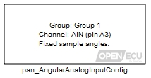
The application must use a pan_AngularAnalogInput_Config block for each input channel to be sampled on an angular basis. A pan_AngularAnalogInput_Config block must be present in the model for other angular analogue input related blocks to operate.
The function identifies the analogue input channel to be sampled. The ECU samples this analogue input channel across the engine cycle, buffering the conversions. The results relative to a cylinder's TDC-firing angle can be retrieved using the pan_AngularAnalogInputVariable block. The results relative to crank zero degrees can be retrieved using the pan_AngularAnalogInputVariableAbs block.
The block identifies the analogue input channel to be sampled and associates the channel with a group name. Other analogue input blocks must refer to the same group name.
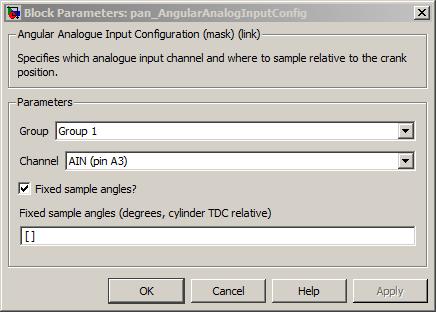
A drop down to identify the group of analogue input channel samples to configure. The selection of groups is dependent on the target ECU hardware selected in the put_Identification block.
Value type: List Calibratable: No Specifies the input channel for the analogue input selected for this Group. The range of selectable channels is dependent on the target ECU hardware selected in the put_Identification block.
Value type: List Calibratable: No Tick to enable the Fixed sample angles mask parameter. When ticked, the application must supply the angles at which to sample the analogue input channel at build time. These angles cannot be modified when the application is running. Untick this mask parameter to supply the sample angles at run-time through either the pan_AngularAnalogInputVariable or pan_AngularAnalogInputVariableAbs block.
Value type: Boolean Calibratable: No Specifies a vector of values specifying the points relative to TDC-firing at which analogue input samples are to be taken. A positive value denotes an angle after TDC-firing. The sample angles are used for each cylinder.
Size: [1, 8] entries
Range: [-360, 360) ° crank, for a two-stroke engine
Range: [-720, 720) ° crank, for a four-stroke engine
None (Main library). (See Section 1.3, “Licensed Features”.)
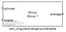
The pan_AngularAnalogInputVariable block retrieves a buffer of sampled analogue input values taken by the ECU relative to the TDC-firing angle of each cylinder. The application provides the sample angles through the angles inport. The application can vary these sample angles while the application runs. The block can provide the samples as an average or individually based on the Average samples? mask parameter.
The angular samples are buffered by the ECU when the TDC-calculation event occurs. See Section 7.2, “Engine TDC-firing events” for a definition of TDC-calculation. If the angles at which the samples are taken are both before and after the TDC-calculation angle, then those samples prior to the TDC-calculation angle will be from the current cycle, but the angles after the TDC-calculation angle will be from one cycle earlier.
The sample angles are resolved to the closest sample (samples occur every 6 degrees throughout the engine cycle).
Identifies the cylinder samples are taken from. Samples are made relative to the cylinder's TDC-firing angle.
Range: [1, n]
where n is the number of cylinders specified by the pan_EngineConfig block.Value type: Integer Specifies a vector of values specifying the points relative to TDC-firing at which analogue input samples are to be taken. A positive value denotes an angle after TDC-firing. The angles are reduced to a resolution of at least 6 crank degrees.
Size: [1, 8] entries
Range: [-360, 360) ° crank, for a two-stroke engine
Range: [-720, 720) ° crank, for a four-stroke engineValue type: Real Only used under simulation. The outport average is set to the value of this inport. Available only if Average samples? is ticked.
Range: [-5, 5] volts
Value type: Real Only used under simulation. Under simulation, the width of this inport is configured to match the width of the outport (as a scalar for an average sample, or a vector for individual samples). The outport samples is set to the value of this inport. Available only if Average samples? is unticked.
Range: [-5, 5] volts
Value type: Real
The average of the angular sample channel calculated and buffered at the last TDC-calculation event. This outport is available when the Average samples? mask parameter is ticked.
Range: [-5, 5] volts
Value type: Real The individual samples of the angular channel buffered at the last TDC-calculation event. This outport is available when the Average samples? mask parameter is unticked.
The outport is a vector of samples. The size of the vector matches the size of the angles inport. The order of the A/D samples given by this outport matches the order of the sample angles given by the angles inport.
Size: [1, 8] entries
Range: [-5, 5] voltsValue type: Real
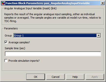
A drop down to identify the group of analogue input channel samples to process (as defined by the pan_AngularAnalogInputConfig block).
Value type: List Calibratable: No Tick to provide the sampled A/D channel information as an average, untick to provide the information as individual samples.
Value type: Boolean Calibratable: No The periodicity of the block execution.
Range: [0.001, 3600] seconds
Value type: Real Calibratable: No Tick to enable inports sim_average or sim_samples.
Value type: Boolean Calibratable: No
None (Main library). (See Section 1.3, “Licensed Features”.)
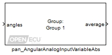
The pan_AngularAnalogInputVariableAbs block retrieves a buffer of sampled analogue input values taken by the ECU relative to crank zero degrees. See Section 7.1.3, “Crankshaft zero degrees” for a definition of crank zero degrees. The application provides the sample angles through the angles inport. The application can vary these sample angles while the application runs. The block can provide the samples as an average or individually based on the Average samples? mask parameter.
The angular samples are buffered by the ECU when the TDC-calculation event occurs. See Section 7.2, “Engine TDC-firing events” for a definition of TDC-calculation. If the angles at which the samples are taken are both before and after the TDC-calculation angle, then those samples prior to the TDC-calculation angle will be from the current cycle, but the angles after the TDC-calculation angle will be from one cycle earlier.
The sample angles are resolved to the closest sample (samples occur every 6 degrees throughout the engine cycle).
A vector of angles where analogue input samples are to be taken. Each angle is relative to crank zero degrees. The angles are reduced to a resolution of at least 6 degrees.
Size: [1, 8] entries
Range: [-360, 360) ° crank, for a two-stroke engine
Range: [-720, 720) ° crank, for a four-stroke engineValue type: Real Only used under simulation. The outport average is set to the value of this inport. Available only if Average samples? is ticked.
Range: [-5, 5] volts
Value type: Real Only used under simulation. Under simulation, the width of this inport is configured to match the width of the outport (as a scalar for an average sample, or a vector for individual samples). The outport samples is set to the value of this inport. Available only if Average samples? is unticked.
Range: [-5, 5] volts
Value type: Real
The average of the angular sample channel calculated and buffered at the last TDC-calculation event. This outport is available when the Average samples? mask parameter is ticked.
Range: [-5, 5] volts
Value type: Real The individual samples of the angular channel buffered at the last TDC-calculation event. This outport is available when the Average samples? mask parameter is unticked.
The outport is a vector of samples. The size of the vector matches the size of the angles inport. The order of the A/D samples given by this outport matches the order of the sample angles given by the angles inport.
Size: [1, 8] entries
Range: [-5, 5] voltsValue type: Real
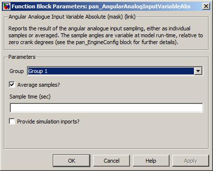
A drop down to identify the group of analogue input channel samples to process (as defined by the pan_AngularAnalogInputConfig block).
Value type: List Calibratable: No Tick to provide the sampled A/D channel information as an average, untick to provide the information as individual samples.
Value type: Boolean Calibratable: No The periodicity of the block execution.
Range: [0.001, 3600] seconds
Value type: Real Calibratable: No Tick to enable inports sim_average or sim_samples.
Value type: Boolean Calibratable: No
Configure a camshaft wheel encoder input channel.
None (Main library). (See Section 1.3, “Licensed Features”.)
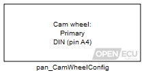
The application must use a pan_CamWheelConfig block for each input channel to be attached to a camshaft encoder wheel. A pan_CamWheelConfig block must be present in the model for other camshaft related blocks to operate. The block identifies the teeth arrangement for one camshaft sensor input, including the maximum expected number of teeth and which teeth edges to record. When the angle clock is running, the application can retrieve the cam wheel tooth record using a pan_CamWheelToothEdgeAngles block with a matching camshaft wheel encoder input channel selection.
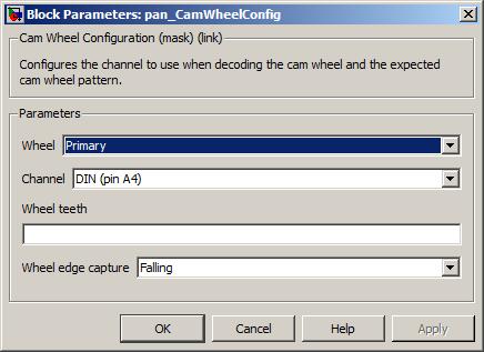
A drop down to identify the camshaft wheel to configure. The selection of wheel is dependent on the target ECU hardware selected in the put_Identification block.
Value type: List Calibratable: No Specifies the input channel for the camshaft sensor input selected for this Wheel. The selection of channel is dependent on the target ECU selected in the put_Identification block.
Value type: List Calibratable: No Specifies the maximum number of teeth, or lobes, of the camshaft wheel encoder. If the camshaft wheel has more teeth than specified here, then some angle information about teeth will not be recorded by the pan_CamWheelToothEdgeAngles block, and the block's count_extra outport will count up.
Range: [1, 13] teeth
Value type: Integer Calibratable: No Specifies the tooth edge type to use when recording teeth angles. Note that the target ECU circuitry may invert the signal (see the ECU's Technical Specification for details about signal inversions).
- Falling
One angle per tooth is captured on the falling edge from the processed sensor signal.
- Rising
One angle per tooth is captured on the rising edge from the processed sensor signal.
- Rising and falling
Two angles per tooth are captured, one for each edge type, from the processed sensor signal.
Value type: List Calibratable: No
Reads the immediate digital state of a camshaft wheel input pin.
None (Main library). (See Section 1.3, “Licensed Features”.)

The pan_CamWheelDigitalInput block provides the instantaneous digital voltage level (high or low) seen at a camshaft wheel input pin. Note that the target ECU circuitry may invert the signal (see the ECU's Technical Specification for details about signal inversions).
Only used under simulation. Under simulation, the value of this inport is passed through to outport state.
Value type: Boolean

A drop down to identify the camshaft wheel input pin to measure. The selection of wheel must match a pan_CamWheelConfig block elsewhere in the model.
Value type: List Calibratable: No The periodicity of the block execution.
Range: [0.001, 3600] seconds, or -1 to inherit the sample time
Value type: Real Calibratable: No Tick to enable inport sim_state.
Value type: Boolean Calibratable: No
Determine whether a camshaft wheel is moving or not.
None (Main library). (See Section 1.3, “Licensed Features”.)
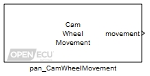
The pan_CamWheelMovement block retrieves whether the camshaft wheel is moving or not. The ECU continually monitors the camshaft wheel input signal looking for tooth edges. If a tooth edge (as defined in the pan_CamWheelConfig block) is detected within a timeout period (approximately 2 seconds), then the ECU declares the wheel as moving. Otherwise, the ECU assumes the wheel is stationary and not moving.
Only used under simulation. Under simulation, the value of this inport is passed through to outport movement.
Value type: Boolean
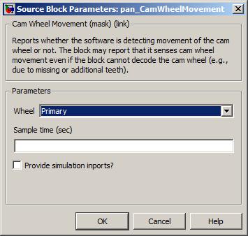
A drop down to identify the camshaft wheel to measure for movement. The selection of wheel must match a pan_CamWheelConfig block elsewhere in the model.
Value type: List Calibratable: No The periodicity of the block execution.
Range: [0.001, 3600] seconds, or -1 to inherit the sample time
Value type: Real Calibratable: No Tick to enable inport sim_movement.
Value type: Boolean Calibratable: No
Retrieve the measured angles of camshaft wheel teeth (rising edges, falling edges or both).
None (Main library). (See Section 1.3, “Licensed Features”.)
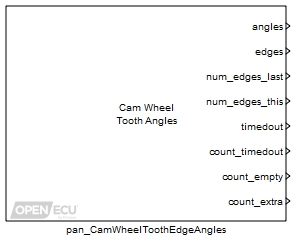
The pan_CamWheelToothEdgeAngles block retrieves information about the processed camshaft wheel signal. The ECU continually monitors the camshaft wheel input, measures the angle of tooth edges and performs a number of operations:
- Angle and edge measurement of teeth
The ECU measures and records the angles and edges of processed cam teeth, relative to crank zero degrees of the primary crankshaft wheel input (see Section 7.1.3, “Crankshaft zero degrees”).
- Timeout check
The ECU measures the duration between cam teeth edges and declares a timeout if no edge is seen for approximately 2 seconds (roughly 30 RPM for a single tooth cam trigger wheel). The ECU accumulates the count of time out events (modulo 16777216), and provides an outport to indicate if the signal is timed out when the block iterates.
- No measurement (empty) indication
The ECU counts the number of engine revolutions where there have been no camshaft wheel teeth detected (modulo 1677216).
- Extra edge error indication
The ECU counts the number of extra edge events seen (modulo 16777216). An extra edge event occurs when more edges than expected are detected in one cam wheel revolution. The number of expected teeth is specified by the application using a pan_CamWheelConfig block.
For example, if there is persistent noise on the camshaft wheel sensor signal then the extra edge count will be incremented at the end of each camshaft revolution. If the pan_CamWheelConfig block is configured for two teeth but the wheel has three teeth, then the extra edge count will be incremented at the end of each camshaft revolution.
Only used under simulation. Under simulation, the values of this vector inport are passed through to outport angles.
Size: [1, n] elements
Range: [0, 360) ° crank, for a two-stroke engine
Range: [0, 720) ° crank, for a four-stroke engine
where n represents the number of edges defined for the same cam wheel by the pan_CamWheelConfig block.Value type: Real Only used under simulation. Under simulation, the values of this vector inport are passed through to outport edges.
Size: [1, n] elements
Range: 0 (falling), 1 (rising) or 2 (not yet sampled)
where n represents the number of edges defined for the same cam wheel by the pan_CamWheelConfig block.Value type: Real Only used under simulation. Under simulation, the values of this vector inport are passed through to outport num_edges_last.
Size: [0, n] elements
where n represents the number of edges defined for the same cam wheel by the pan_CamWheelConfig block.Value type: Real Only used under simulation. Under simulation, the values of this vector inport are passed through to outport num_edges_this.
Size: [0, n] elements
where n represents the number of edges defined for the same cam wheel by the pan_CamWheelConfig block.Value type: Real Only used under simulation. Under simulation, the value of this inport is passed through to outport timedout.
Value type: Boolean Only used under simulation. Under simulation, the value of this inport is passed through to outport count_timedout.
Range: [0, 16777215] counts
Value type: Integer Only used under simulation. Under simulation, the value of this inport is passed through to outport count_empty.
Range: [0, 16777215] counts
Value type: Integer Only used under simulation. Under simulation, the value of this inport is passed through to outport count_extra.
Range: [0, 16777215] counts
Value type: Integer
The measured angle or angles of the processed camshaft wheel teeth edges, as defined by the pan_CamWheelConfig block. The angles are relative to zero degrees of the primary crankshaft wheel input, as described in Section 7.1.3, “Crankshaft zero degrees”, adjusted by the application declared engine angle offset, as described in Section 7.2.4, “Engine angle offset”.
For example, if a tooth edge is detected 15 degrees after crank zero degrees, and the application has not declared engine sync, then the block will report the angle as 15. If the application subsequently declares engine sync with an angle offset of 360 crank degrees, then the block will report the angle as 375.
When the ECU loses synchronisation with the primary crankshaft then the values of the angles output are reset to zero.
Size: [1, n] elements
Range: [0, 360) ° crank, for a two-stroke engine
Range: [0, 720) ° crank, for a four-stroke engine
Resolution: at least 0.1 degrees
where n represents the number of edges defined for the same cam wheel by the pan_CamWheelConfig block.Value type: Real Corresponding measurement of the tooth edge for each tooth angle, either falling, rising or not yet sampled.
When the ECU loses synchronisation with the primary crankshaft then the values of the edges output are reset to not yet sampled.
Size: [1, n] elements
Range: 0 (falling), 1 (rising) or 2 (not yet sampled)
where n represents the number of edges defined for the same cam wheel by the pan_CamWheelConfig block.Value type: Real The number of camshaft trigger wheel teeth edges captured in the last engine revolution (from engine tooth one to engine tooth one).
Size: [0, n] elements
where n represents the number of edges defined for the same cam wheel by the pan_CamWheelConfig block.Value type: Real The number of camshaft trigger wheel teeth edges captured in this engine revolution (from engine tooth one to the current engine tooth).
Size: [0, n] elements
where n represents the number of edges defined for the same cam wheel by the pan_CamWheelConfig block.Value type: Real Set to one when a cam wheel tooth edge has not been detected in approximately 2 seconds. With a single toothed cam trigger wheel, this equates to approximately 30 RPM. The duration of the time out is fixed by the block.
Value type: Boolean A count of the time outs, wrapped modulo 16777216.
Range: [0, 16777215] counts
Value type: Integer A count of engine revolutions where no camshaft teeth edges are detected, wrapped modulo 16777216. An engine revolution starts at crank zero degrees and ends one or two crank revolutions later. The number of crank revolutions depends on the engine type selected by the pan_EngineConfig block.
Range: [0, 16777215] counts
Value type: Integer A count of extra edge events, wrapped modulo 16777216. An extra edge event occurs when more than the expected number of edges are detected per camshaft revolution. An engine revolution starts at crank zero degrees and ends one or two crank revolutions later. The number of crank revolutions depends on the engine type selected by the pan_EngineConfig block.
Range: [0, 16777215] counts
Value type: Integer
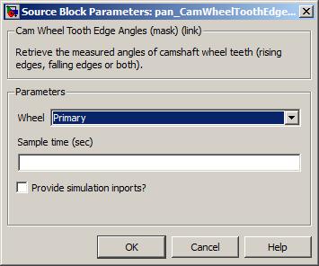
A drop down to identify the camshaft wheel for angle measurement. The selection of wheel must match a pan_CamWheelConfig block elsewhere in the model.
Value type: List Calibratable: No The periodicity of the block execution.
Range: [0.001, 3600] seconds, or -1 to inherit the sample time
Value type: Real Calibratable: No Tick to enable inports sim_angles, sim_edges, sim_timedout, sim_count_timedout, sim_count_empty, sim_count_extra.
Value type: Boolean Calibratable: No
Retrieve the current crankshaft wheel angle.
None (Main library). (See Section 1.3, “Licensed Features”.)
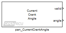
The pan_CurrentCrankAngle block retrieves the current angle of the crankshaft wheel encoder, relative to crank zero degrees (see Section 7.1.3, “Crankshaft zero degrees”). The retrieved value is taken from the angle clock, which is an estimate of crank decoding and position identification process (Section 7.1.4, “Angle clock”).
Set to zero when the ECU cannot provide a crank angle (for instance, the ECU has not gained region synchronisation with the crankshaft wheel encoder), or set to one when the outport angle is valid.
Value type: Boolean The estimated angle of the crankshaft wheel. If the crank wheel is primary, then the value is taken from the angle clock (which is itself an estimate of the wheel position between teeth). If the crank wheel is secondary, then the value is taken from the last decoded tooth (and therefore with reduced resolution).
Range: [0, 360) ° crank
Resolution: at least 0.1 degrees, for the primary crank wheel
Resolution: per tooth for secondary crank wheelsValue type: Real
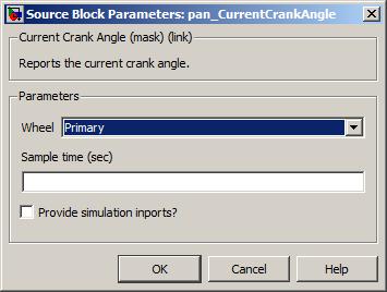
A drop down to identify the crankshaft wheel for angle measurement. The selection of wheel must match a pan_CrankWheelConfig block elsewhere in the model.
Value type: List Calibratable: No The periodicity of the block execution.
Range: [0.001, 3600] seconds, or -1 to inherit the sample time
Value type: Real Calibratable: No Tick to enable inports sim_valid and sim_angle.
Value type: Boolean Calibratable: No
Configure a crankshaft wheel encoder input channel.
None (Main library). (See Section 1.3, “Licensed Features”.)
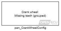
The application must use a pan_CrankWheelConfig block for each input channel to be attached to a crankshaft encoder wheel. A pan_CrankWheelConfig block must be present in the model for other crankshaft related blocks to operate. The block identifies the teeth arrangement for one crankshaft sensor input, including the number of teeth, sync points and their type.
The block supports crank trigger wheels with missing teeth or an extra tooth. Common crank trigger wheels, such as 12+1 and 36-1 are supported:
As are less common wheel patterns, such as 24-1-1-1 or 36-1-2-3:
Where supported, the application can use the pan_CrankWheelConfigExt block to further define how the crankshaft signal is processed for electrical noise, sync point detection and more.
See Section 7.1.1, “Crankshaft position sensor processing” for a general description of how the ECU processes different crank sensor signals, and see the ECU's Technical Specification for details specific to an ECU. In particular, note that some ECUs (such as the M670) invert the crankshaft sensor signal in circuitry, which must be taken in to account with the Tooth edge polarity mask parameter. Please see the crank sensor input section of the ECU's Technical Specification to determine polarity settings. The ECU does not diagnose an inverted crank signal.
The block makes a distinction between primary and secondary crankshaft encoding wheels. A primary wheel can drive the angle clock, as described in Section 7.1.4, “Angle clock”. A secondary wheel cannot drive the angle clock but can be used to determine phasing between the primary wheel and itself.

A drop down to identify the crankshaft wheel to configure. The selection of wheel is dependent on the target ECU hardware selected in the put_Identification block.
Value type: List Calibratable: No Specifies the input channel for the crankshaft sensor input selected for this Wheel. The selection of channel is dependent on the target ECU selected in the put_Identification block.
Value type: List Calibratable: No Specifies the expected pattern of teeth on the crankshaft encoding Wheel. The selection of wheel type is dependent on the target ECU selected in the put_Identification block.
- Missing teeth (grouped)
A crankshaft wheel encoder with a series of equally spaced teeth followed by a gap equal in width to 1 or more teeth (the gap is often referred to as “missing teeth”).
- Extra teeth (grouped)
A crankshaft wheel encoder with a series of equally spaced teeth with an extra tooth placed equally between two others.
Value type: List Calibratable: No Specifies the algorithm to use when detecting crank synchronisation points (see Section 7.1.2.2, “Crank wheel sync points”. The selection of algorithm is dependent on the target ECU selected in the put_Identification block.
Value type: List Calibratable: No Specifies the number of teeth on the crankshaft encoding wheel, plus any missing teeth but ignoring an extra teeth. For example, use 60 for a 60-2 wheel, 36 for a 36-1-1 wheel, 12 for a 12+1 wheel, and 12 for a 12+1+1 wheel.
Range: [12, 60] teeth
Value type: Integer Calibratable: No Specifies the number of teeth involved in one of the sync points of the crankshaft wheel encoder. Negative integers indicate missing teeth, positive integers represent extra teeth.
Range: [-1, -3] or 1, crank teeth
Value type: Integer Calibratable: No Specifies the polarity of the input signal to be used as the tooth indication when decoding the crankshaft wheel. Note that this polarity refers to the processed signal to the microprocessor, and therefore its meaning with respect to the polarity on the external pin varies between target ECUs, as detailed below.
- Default
With this choice, for a Hall-effect signal, a falling edge is the tooth indication. For a VR signal, the tooth indication always corresponds to the zero crossing point where the positive signal falls below the negative signal. Note that for a VR signal, the default selection should always be preferred, since the other edge of the processed signal will correspond to the arming point (when the voltage rises above a threshold that depends on the previous peak values) and is less accurate as a reference point. Since a variable reluctance sensor typically has two output signals, one can always ensure that the positive-to-negative zero crossing point matches the desired tooth indication by swapping the connections if necessary.
- Falling
The interpretation of this field depends on the target ECU hardware selected in the put_Identification block. For the M221 and M250 targets, “Falling” is the same as “Default”.
- Rising
The interpretation of this field depends on the target ECU hardware selected in the put_Identification block. For the M220 and M670 targets, “Rising” is the same as “Default”.
Value type: List Calibratable: No
Configure the extended parameters for decoding a crankshaft wheel encoder, including missing tooth detection, noise rejection and stall detection.
None (Main library). (See Section 1.3, “Licensed Features”.)
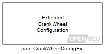
The pan_CrankWheelConfigExt block configures sync point detection, noise rejection and stall detection parameters for decoding one or more crankshaft sensor inputs. A detailed explanation of the parameters is given in Section 7.1.2.4, “Crank decoding”.
If this block is not present in an application model then the parameters default, as detailed in each of the mask parameters. A pan_CrankWheelConfig block must be present in the model for the other crankshaft related blocks to operate.
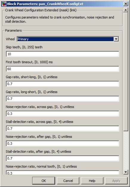
A drop down to identify the crankshaft wheel to configure. The selection of wheel is dependent on the target ECU hardware selected in the put_Identification block.
Value type: List Calibratable: No Number of processed teeth edges to ignore during ECU initialisation, used to ignore electrical noise during power up. Set to zero to calibrate out this decoding step.
Range: [0, 255] teeth
Value type: Integer Calibratable: Yes, offline The minimum time between processed teeth edges before the crank decode logic will continue. Effectively sets the minimum speed before searching for crank synchronisation. Set to zero to calibrate out this decoding step.
Range: [0, 1000] milliseconds
Value type: Real Calibratable: Yes, offline The ratio of the inter-tooth time immediately before the missing tooth region to the time across the missing tooth region, below which the crank decode logic determines a missing tooth region has been detected.
Range: [0, 1)
Value type: Real Calibratable: Yes, offline The ratio of the inter-tooth time immediately after the missing tooth region to the time across the missing tooth region, below which the crank decode logic determines a missing tooth region has been detected.
Range: [0, 1)
Value type: Real Calibratable: Yes, offline Noise-rejection ratio, across gap
The ratio of the inter-tooth time that the crank decode logic will ignore processed crank teeth edges, for the tooth immediately proceeding the missing tooth region. Set to zero to remove noise-rejection functionality.
Range: [0, 1)
Value type: Real Calibratable: Yes, offline Stall-detection ratio, across gap
The ratio of the inter-tooth time proceeding the missing tooth region, added to the next expected tooth edge, to calculate the crank stall timeout. If a processed tooth edge has not been seen by the timeout, the crank decode logic will assume the wheel has stalled.
Range: [0, 4)
Value type: Real Calibratable: Yes, offline Noise-rejection ratio, after gap
The ratio of the inter-tooth time that the crank decode logic will ignore processed crank teeth edges, for the tooth immediately after the missing tooth region. Set to zero to remove noise-rejection functionality.
Range: [0, 1)
Value type: Real Calibratable: Yes, offline Stall-detection ratio, after gap
The ratio of the inter-tooth time after missing tooth region, added to the next expected tooth edge, to calculate the crank stall timeout. If a processed tooth edge has not been seen by the timeout, the crank decode logic will assume the wheel has stalled. The inter-tooth time is calculated using the missing tooth region time, divided as if there were no missing teeth.
Range: [0, 4)
Value type: Real Calibratable: Yes, offline Noise-rejection ratio, normal tooth
The ratio of the inter-tooth time that the crank decode logic will ignore processed crank teeth edges, for teeth not immediately before or after the missing tooth region. Set to zero to remove noise-rejection functionality.
Range: [0, 1)
Value type: Real Calibratable: Yes, offline Stall-detection ratio, normal tooth
The ratio of the inter-tooth time added to the next expected tooth edge, to calculate the crank stall timeout. If a processed tooth edge has not been seen by the timeout, the crank decode logic will wait for a further tooth time (see Stall-detection ratio, timeout tooth) before declaring crank stall.
Range: [0, 4)
Value type: Real Calibratable: Yes, offline Noise-rejection ratio, timeout tooth
If the crank decode logic declares crank stall for a normal tooth, the crank decode logic will try waiting an additional period of time before declaring stall. The ratio is used as before. Set to zero to remove noise-rejection functionality.
Range: [0, 1)
Value type: Real Calibratable: Yes, offline Stall-detection ratio, timeout tooth
If the crank decode logic declares crank stall for a normal tooth, the crank decode logic will try waiting an additional period of time before declaring stall. The ratio is used as before. If this second timeout triggers then the crank decode logic declares the crank stalled.
Range: [0, 4)
Value type: Real Calibratable: Yes, offline
Reads the immediate digital state of a crankshaft wheel input pin.
None (Main library). (See Section 1.3, “Licensed Features”.)
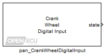
The pan_CrankWheelDigitalInput block provides the instantaneous digital voltage level (high or low) seen at a crankshaft wheel input pin. Note that the target ECU circuitry may invert the signal (see the ECU's Technical Specification for details about signal inversions).
Only used under simulation. Under simulation, the value of this inport is passed through to outport state.
Value type: Boolean Calibratable: No
Set to zero if the voltage level on the crankshaft wheel pin is low, set to one if the voltage level on the crank pin is high. Note that the target ECU circuitry may invert the signal (see the ECU's Technical Specification for details about signal inversions).
Value type: Boolean Calibratable: No
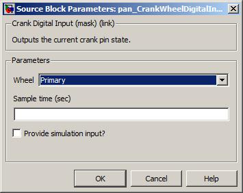
A drop down to identify the crankshaft wheel to measure. The selection of wheel must match a pan_CrankWheelConfig block elsewhere in the model.
Value type: List Calibratable: No The periodicity of the block execution.
Range: [0.001, 3600] seconds
Value type: Real Calibratable: No Tick to enable inport sim_state.
Value type: Boolean Calibratable: No
Retrieve the last error detected and current state of decoding a crankshaft wheel input.
None (Main library). (See Section 1.3, “Licensed Features”.)

The pan_CrankWheelDecodeState block retrieves the current state of decoding the crankshaft sensor signal. A detailed description of the decoding state machine can be found in Section 7.1.2.4, “Crank decoding”. For reference, the decoding state values are:
The pan_CrankWheelDecodeState block retrieves the last detected error when processing the crank signal, indicating for example, that crank region synchronisation was lost due to a timeout between teeth arrival times (stall) or that crank region synchronisation was lost due to the wrong number of counted teeth between sync points.
The current state whilst decoding the crankshaft sensor signal. See the description of decoding states in Section 7.1.2.4, “Crank decoding”.
Value type: Integer A bitmap representing the last detected error whilst decoding the crankshaft sensor signal. When this block is iterated, the bitmap is cleared to zero. The bitmap is the summation of the values give in Table 7.2, “Crankshaft signal decoding error bitmap values”. For instance, the error value 40 means the decoding state machine lost synchronisation with the crank signal just before a sync point.
Table 7.2. Crankshaft signal decoding error bitmap values
Value Description 0 No error detected whilst decoding. 1 An error internal to decoding state machine occurred. Please contact OpenECU technical support if this error occurs. 2 An error internal to decoding state machine occurred. Please contact OpenECU technical support if this error occurs. 4 An error internal to decoding state machine occurred. Please contact OpenECU technical support if this error occurs. 8 The crankshaft has stalled (the time between consecutive teeth is sufficiently low that the ECU cannot tell if the crankshaft is moving or not). See Section 7.1.2.1, “Crank wheel movement and stall detection” for a description of stall detection. 16 The crankshaft has stalled whilst waiting for a tooth not immediately before, during, or immediately after the sync point. 32 The crankshaft has stalled whilst waiting for the tooth immediately before the sync point. 64 The crankshaft has stalled whilst waiting for the tooth immediately after the sync point. 128 The decoding state machine has lost region synchronisation because of a tooth found in a missing teeth sync point. This error condition can occur if the wrong sync point type has been selected in the pan_CrankWheelConfig block or if the wrong number of teeth have been provided by the pan_CrankWheelConfig or pan_CrankWheelSyncPointNext block. 256 The decoding state machine has lost region synchronisation because the extra tooth of a sync point was not found. This error condition can occur if the wrong sync point type has been selected in the pan_CrankWheelConfig block or if the wrong number of teeth have been provided by the pan_CrankWheelConfig or pan_CrankWheelSyncPointNext block. 512 The decoding state machine has lost region synchronisation because the application requested loss of sync through the pan_EngineDeclareSync block.
Value type: Integer

A drop down to identify the crankshaft wheel for speed measurement. The selection of wheel must match a pan_CrankWheelConfig block elsewhere in the model.
Value type: List Calibratable: No The periodicity of the block execution.
Range: [0.001, 3600] seconds
Value type: Real Calibratable: No Tick to enable inports sim_state and sim_error.
Value type: Boolean Calibratable: No
Determine whether a crankshaft wheel is moving or not.
None (Main library). (See Section 1.3, “Licensed Features”.)
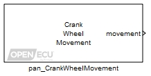
The pan_CrankWheelMovement block retrieves whether the crankshaft wheel is moving or not. The ECU continually monitors the crankshaft wheel input signal looking for tooth edges. If the crankshaft signal decoding state machine has reached state Detect AB or higher, then the ECU declares the wheel as moving. See Section 7.1.2.4, “Crank decoding” for a description of the crank decoding state machine.
Only used under simulation. Under simulation, the value of this inport is passed through to outport movement.
Value type: Boolean

A drop down to identify the crankshaft wheel to measure for movement. The selection of wheel must match a pan_CrankWheelConfig block elsewhere in the model.
Value type: List Calibratable: No The periodicity of the block execution.
Range: [0.001, 3600] seconds
Value type: Real Calibratable: No Tick to enable inport sim_movement.
Value type: Boolean Calibratable: No
Retrieve the phase angle of a secondary crankshaft wheel relative to the primary wheel.
None (Main library). (See Section 1.3, “Licensed Features”.)
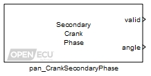
The pan_CrankSecondaryPhase block provides the current phase angle of the specified secondary crankshaft wheel relative to the primary crankshaft wheel that generates the angle clock. The crankshaft encoder wheel pattern need not be the same for the primary and secondary inputs.
The ECU continuously monitors the primary and secondary crankshaft wheel signals. The ECU measures the phase on each tooth of a secondary crankshaft wheel, as the difference between the angle clock of the primary crankshaft wheel and the angle of the secondary crankshaft wheel tooth.
The phase angle is always a value between 0° and 360° and represents the secondary wheel angle minus the primary wheel angle, so that if the secondary wheel is 10° in advance of the primary, it will return a value of 10, and if the primary wheel is 10° in advance of the secondary it will return a value of 350.
Set to zero when the ECU cannot provide a phase angle (for instance, if the ECU has not synchronised with both the primary and the selected secondary crankshaft wheels), set to one when the outport angle is valid.
Value type: Boolean The estimated phase angle of the specified secondary crankshaft wheel encoder relative to the primary crankshaft wheel encoder.
Range: [0, 360) ° crank
Resolution: at least 0.1 degreesValue type: Real

A drop down to identify the crankshaft wheel for angle measurement. The selection of wheel must match a pan_CrankWheelConfig block elsewhere in the model. There must also be a pan_CrankWheelConfig block for the Primary crank wheel present in the model.
Value type: List Calibratable: No The periodicity of the block execution.
Range: [0.001, 3600] seconds
Value type: Real Calibratable: No Tick to enable inports sim_valid and sim_angle.
Value type: Boolean Calibratable: No
Calculate the rotational speed of a crankshaft wheel.
None (Main library). (See Section 1.3, “Licensed Features”.)
The pan_CrankWheelSpeed block provides the rotational speed of a crankshaft wheel. The Type mask parameter selects the speed calculation output by the block.
Only used under simulation. Under simulation, the value of this inport is passed through to outport speed.
Range: [0, 10000] rpm
Value type: Real
The measured speed of the crankshaft wheel encoder selected by parameter Wheel.
Range: [0, 10000] rpm
Value type: Real
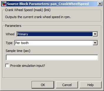
A drop down to identify the crankshaft wheel for speed measurement. The selection of wheel must match a pan_CrankWheelConfig block elsewhere in the model.
Value type: List Calibratable: No A drop down to specify the speed calculation to perform. The selection of type is dependent on the target ECU hardware selected in the put_Identification block.
- Per crank wheel revolution
The speed as measured every 360° crank.
- Per tooth
The speed as calculated from the time between the last two crank teeth. When calculating a speed across a missing tooth sync point, the block adjusts the speed as if there were physical teeth present. Extra sync point teeth are ignored.
Value type: List Calibratable: No The periodicity of the block execution.
Range: [0.001, 3600] seconds
Value type: Real Calibratable: No Tick to enable inport sim_speed.
Value type: Boolean Calibratable: No
Retrieve the synchronisation state for a crankshaft wheel.
None (Main library). (See Section 1.3, “Licensed Features”.)
The pan_CrankWheelSync block retrieves whether the ECU has synchronised to the crankshaft wheel or not. The ECU continually monitors the crankshaft wheel input signal looking for tooth edges. If the crankshaft signal decoding state machine has reached state Count teeth or higher, then the ECU has synchronisation to the wheel. See Section 7.1.2.4, “Crank decoding” for a description of the crank decoding state machine.
Only used under simulation. Under simulation, the value of this inport is passed through to outport sync.
Value type: Boolean
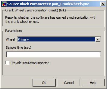
A drop down to identify the crankshaft wheel for synchronisation information. The selection of wheel must match a pan_CrankWheelConfig block elsewhere in the model.
Value type: List Calibratable: No The periodicity of the block execution.
Range: [0.001, 3600] seconds
Value type: Real Calibratable: No Tick to enable inport sim_sync.
Value type: Boolean Calibratable: No
Retrieve information about the last successfully decoded crankshaft wheel sync point.
None (Main library). (See Section 1.3, “Licensed Features”.)

The pan_CrankWheelSyncPointLast block retrieves information about the last successfully decoded crankshaft wheel sync point. This includes the number of counted teeth for that region, and the A, B and a sync point timing. A description of what constitutes a crank region, a sync point and sync point timing, can be found in Section 7.1.2.2, “Crank wheel sync points” and Section 7.1.2.3, “Sync point detection”.
The pan_CrankWheelSyncPointLast block can be used by the application to determine which region of the crankshaft wheel has been successfully decoded. For crankshaft wheels with more than one sync point, the application must provide details about the next crank region using the pan_CrankWheelSyncPointNext blocks from a subsystem triggered from a corresponding pan_CrankWheelSyncPointTrigger block. More details are provided in Section 7.1.2.5, “Maintaining crank synchronisation”.
Note that for crankshaft wheels that have one sync point, the ECU will maintain synchronisation to the crank wheel using the decoding state machine without the need for the application to use the pan_CrankWheelSyncPointTrigger, pan_CrankWheelSyncPointLast and pan_CrankWheelSyncPointNext blocks.
Only used under simulation. Under simulation, the value of this inport is passed through to the teeth outport.
Value type: Integer Only used under simulation. Under simulation, the value of this inport is passed through to the before outport.
Value type: Integer Only used under simulation. Under simulation, the value of this inport is passed through to the sync_point outport.
Value type: Integer Only used under simulation. Under simulation, the value of this inport is passed through to the after outport.
Value type: Integer
The number of counted teeth in the successfully decoded crank region.
Range: [3, n] where n is the number of physical crank teeth as specified in the corresponding pan_CrankWheelConfig block.
Value type: Integer The duration of sync point time A.
Range: [1, 2000000] microseconds
The upper range is approximate and varies between ECUs.Value type: Real The duration of sync point time B.
Range: [1, 2000000] microseconds
The upper range is approximate and varies between ECUs.Value type: Real The duration of sync point time a.
Range: [1, 2000000] microseconds
The upper range is approximate and varies between ECUs.Value type: Real

A drop down to identify the crankshaft wheel for speed measurement. The selection of wheel must match a pan_CrankWheelConfig block elsewhere in the model.
Value type: List Calibratable: No The periodicity of the block execution.
Range: [0.001, 3600] seconds
Value type: Real Calibratable: No Tick to enable inports sim_teeth, sim_before, sim_sync_point and sim_after.
Value type: Boolean Calibratable: No
Provide information about the next crank region to the ECU.
None (Main library). (See Section 1.3, “Licensed Features”.)

The pan_CrankWheelSyncPointNext block provides information about the next crank region to the ECU. This includes the number of expected teeth for that region (ignoring any extra teeth), and the number of teeth that represent the sync point. A description of what constitutes a crank region can be found in Section 7.1.2.2, “Crank wheel sync points”.
The pan_CrankWheelSyncPointNext block is used maintain synchronisation to a crankshaft wheel when the wheel has more than one sync point. The application must read information about the previous crank region and sync point using the pan_CrankWheelSyncPointLast block from a subsystem triggered from a corresponding pan_CrankWheelSyncPointTrigger block. More details are provided in Section 7.1.2.5, “Maintaining crank synchronisation”.
Note that for crankshaft wheels that have one sync point, the ECU will maintain synchronisation to the crank wheel using the decoding state machine without the need for the application to use the pan_CrankWheelSyncPointTrigger, pan_CrankWheelSyncPointlast and pan_CrankWheelSyncPointNext blocks.
The number of teeth for the next crank region.
Range: [3, n]
where n is the number of physical crank teeth as specified in the corresponding pan_CrankWheelConfig block.Value type: Integer The number of teeth involved in the sync point at the end of the next crank region. Negative integers indicate missing teeth, positive integers represent extra teeth.
Range: [-1, -3] or 1, crank teeth
Value type: Integer

A drop down to identify the crankshaft wheel for speed measurement. The selection of wheel must match a pan_CrankWheelConfig block elsewhere in the model.
Value type: List Calibratable: No The periodicity of the block execution.
Range: [0.001, 3600] seconds
Value type: Real Calibratable: No
Generate an asynchronous function-call trigger for each detected crankshaft wheel sync point.
None (Main library). (See Section 1.3, “Licensed Features”.)

The pan_CrankWheelSyncPointTrigger block generates an asynchronous function-call trigger for each detected crankshaft wheel sync point. The application uses the function-call trigger to determine which sync point has occurred and to supply information for the following crank region. See Section 7.1.2.5, “Maintaining crank synchronisation” for a description of how this works.
Note that for crankshaft wheels that have one sync point, the ECU will maintain synchronisation to the crank wheel using the decoding state machine without the need for the application to use the pan_CrankWheelSyncPointTrigger, pan_CrankWheelSyncPointLast and pan_CrankWheelSyncPointNext blocks.

A drop down to identify the crankshaft wheel for which a trigger will be generated. The selection of wheel must match a pan_CrankWheelConfig block elsewhere in the model.
Value type: List Calibratable: No
Retrieve the current crankshaft wheel tooth identifier.
None (Main library). (See Section 1.3, “Licensed Features”.)
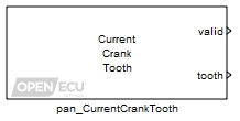
The pan_CurrentCrankTooth block retrieves the current tooth identifier of the crankshaft wheel. See Section 7.1.5, “Crank tooth identification” for a description of crank tooth identifiers.
Set to zero when the ECU cannot provide a crank tooth (for instance, the ECU has not synchronised to the crankshaft wheel encoder), set to one when the outport tooth is valid.
Value type: Boolean The identifying number of the last detected tooth of the crankshaft wheel encoder. The reported identifier is adjusted by the tooth offset supplied to the pan_EngineDeclareSync block.
Range: [1, n] tooth
where n is the number of physical teeth on the crankshaft wheel.Value type: Integer
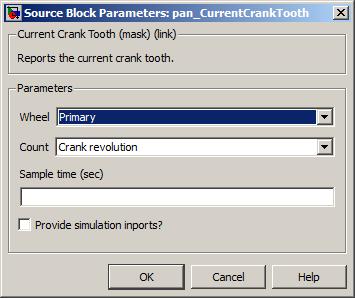
A drop down to identify the crankshaft wheel for tooth measurement. The selection of wheel must match a pan_CrankWheelConfig block elsewhere in the model.
Value type: List Calibratable: No The periodicity of the block execution.
Range: [0.001, 3600] seconds
Value type: Real Calibratable: No Tick to enable inports sim_valid and sim_tooth.
Value type: Boolean Calibratable: No
Configures basic information for a angular digital output on a particular channel.
None (Main library). (See Section 1.3, “Licensed Features”.)
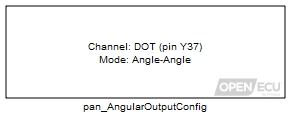
The pan_AngularOutputConfig block configures the properties of an angular digital output. The digital output can be controlled from multiple task rates using a pan_AngularOutput block, but requires a single configuration block.
The pan_AngularOutputConfig block configures the digital output in one of two modes: Angle-Angle and Angle-Time. Both allow an action to occur at a specific angle (either relative to crank zero degrees or relative to TDC-firing for a given cylinder). A second action then occurs after a specified duration. For Angle-Angle mode, the duration is an angle, whereas for Angle-Time mode the duration is a time. The output mode is a fixed feature of the output specified in the configuration block.
The pan_AngularOutputConfig block configures the default output state when neither half or full engine synchronisation is active (see Section 7.1.9, “Engine synchronisation modes” for details), or when the ECU first powers on.
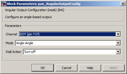
Specifies the output channel to configure.
Value type: List Calibratable: No Specifies the output mode which can be Angle-Angle or Angle-Time.
Value type: List Calibratable: No Specifies the pin state to be output when the engine stalls, i.e. when neither half or full engine synchronisation is active. This also determines the pin state to be output when the ECU is first powered on.
Value type: List Calibratable: No
Control an angular digital output.
None (Main library). (See Section 1.3, “Licensed Features”.)
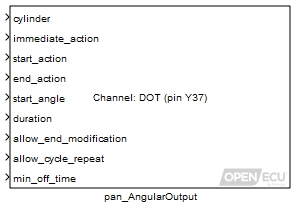
The pan_AngularOutput block allows an application to control an output in the angular domain in a fairly generic way by specifying start and end actions on a digital output pin state. The start actions are always specified to occur at a start angle, while the end actions are specified to occur at some duration after the start angle. The duration can be either an angle or a time depending on the output mode selected. Note that the output mode is a fixed property of the output that is specified by the corresponding pan_AngularOutputConfig block. Possible actions are setting the pin-state to active or inactive, toggling the state or leaving the state unchanged.
In addition to controlling the output in the angular domain, the block allows an immediate action to be specified. This allows a relatively crude level of purely time-based control to occur at the resolution of the block task time. An example application might be to control an output using this immediate action before crank synchronisation, and then use the angular control once crank sync had been attained.
Some illustrations of the block in action are given below.


Multiple instances of the pan_AngularOutput block associated with a given channel are allowed, to allow the output to be controlled more easily both in the angular and time domain. However a single instance of the pan_AngularOutputConfig block must exist for each channel used.
Note
Care must be taken when using multiple instances of the pan_AngularOutput block on the same channel, since they will potentially be in competition.
The start angle is interpreted either relative to crank-zero, or relative to the TDC-firing angle of a specified cylinder number. The specified start event will then occur at the next such start angle to occur. For a two-stroke engine (as specified by the pan_EngineConfig block), the start angle is interpreted modulo 360 degrees. For a four-stroke engine, the start angle is interpreted modulo 360 degrees in half engine synchronisation mode, and modulo 720 degrees in full engine synchronisation mode.
When the ECU is in neither half or full engine synchronisation mode, the output can be scheduled but will not be driven as the engine position will be unknown. If engine synchronisation is lost, then the output pin state is set to the value specified in the Stall action) mask parameter of the corresponding pan_AngularOutputConfig block. This also determines the initial output state before the current block has ever run.
The pan_AngularOutput supports the scheduling of a sequence of up to six events at a time. Each event has a different start action, end action, start angle, and duration, specified as a mux of values to the block inports. The sequence of events can be modified at any time during the engine cycle, to add, remove, or modify existing events. The updated values will take effect on the current engine cycle if the start angle of the next scheduled pulse has not been reached when the block is iterated, or on the next engine cycle if the start angle has already been reached for the current engine cycle. If the duration of an event is set to zero, then it will be skipped.
The sequence of events specified by the pan_AngularOutput can be repeated automatically every engine cycle by setting the allow_cycle_repeat inport to one. If the allow_cycle_repeat inport is set to zero then a single sequence of events will be scheduled, and a further block iteration is required to generate further events. If the pan_AngularOutput iterates before the next scheduled event has started, and the start angle of the new data is still in the future, then the new data will supersede the previous data. If the start angle of the new data is in the past, and the previous data is in the future, then the previous data will be used for only the next event instead of scheduling the event for the next engine cycle. The preference being that it is better to keep the previously scheduled event, than to skip the event for the current engine cycle.
Each index in the mux of values is treated as a separate event. If the block iterates while an event is underway and the data for the current event in the mux of values is modified, then the behaviour is determined by the allow_end_modification inport value. If this is zero, then the data will be buffered and take effect on the next instance of that event. On the other hand, if the allow_end_modification inport value is one, then the end of the event will be updated according to the newly provided duration and end_action values (and the start_action and start_angle values are ignored). If the newly provided duration has already elapsed, then the end_action is applied immediately. (Note that in this case it will be applied immediately after any immediate_action that has been specified.)


If the duration for an event is zero, then that event will be skipped for the schedule of events. If the duration for all events in the schedule are set to zero, then at the start_angle of the event in the first index of the schedule, a single action will be performed corresponding to the result of applying the start_action followed by the end_action. For example, if both actions specify that the output pin state should be toggled, then no change to the pin state will occur. If an update occurs when an event is underway with duration of zero and allow_end_modification set to one, then the newly specified end_action is applied immediately.
The possible values for the inports immediate_action, start_action, and end_action are:
Table 7.3. Angular digital output pin actions
| Value | Description |
|---|---|
| 0 | Turn-off - the output pin will be modified to the non-driven state. |
| 1 | Turn-on - the output pin will be modified to the driven state. |
| 2 | Toggle - the output pin will be toggled. |
| 3 | No-action - the output pin will not change driven state. |
If two events in a schedule overlap, the first pulse will be terminated at the start angle of the next pulse with a single action corresponding to the result of applying the end_action of the first event followed by the start_action of the next event. The schedule will then continue normally with the duration of the next event, resulting in the correct timing of the next event from that event's start_angle.

If an event start_action occurs within the min_off_time after the end_action of a previous event, the second event will be delayed to ensure the min_off_time is maintained between the two events. The min_off_time can be set to zero to prevent the subsequent pulse from being delayed.

This determines how the start_angle is to be interpreted. If zero is passed, then the start_angle inport is interpreted relative to crank zero degrees. If a number between 1 and the number of cylinders is passed, then the start_angle is interpreted relative to that cylinder's TDC-firing angle.
Range: 0 or [1, n]
where n is the number of cylinders specified by the pan_EngineConfig block.Value type: Integer The action to apply immediately (i.e. when the block iterates) to the output state, as specified by Table 7.3, “Angular digital output pin actions”.
Value type: Integer A vector of actions to apply to the output state at the angle specified by start_angle, as specified by Table 7.3, “Angular digital output pin actions”. This vector may contain up to six elements and must be the same width and have the same ordering as the end_action, start_angle, and duration vectors.
Value type: Integer A vector of actions to apply to the output state after the specified duration has elapsed since the start_angle, as specified by Table 7.3, “Angular digital output pin actions”. This vector may contain up to six elements and must be the same width and have the same ordering as the start_action, start_angle, and duration vectors.
Value type: Integer A vector of requested start angles for the beginning of the output event. The interpretation of this angle is determined by the value passed to the cylinder inport. The value of the angle is folded to the range modulo 360° or 720° as appropriate as explained above. This vector may contain up to six elements and must be the same width and have the same ordering as the start_action, end_action, and duration vectors.
Range: [-720, 720] °
Resolution: at least 0.1 degreesValue type: Real A vector of either angles or times depending on the Mode specified in the instance of the pan_AngularOutputConfig block that exists for this channel. When the Mode is Angle-Angle, then the durations are angles in degrees; if it is Angle-Time then the durations are times in milliseconds. The duration specifies when after the start_angle to apply the pin action specified by the end_action. This vector may contain up to six elements and must be the same width and have the same ordering as the start_action, end_action, and start_angle vectors.
Range: [0, 360000] ° or [0, 2000] milliseconds
Value type: Real A flag that applies only when an event is currently underway. Set to one to update the duration and end_action information immediately. Set to zero to buffer the data to be used on the next instance of the event.
Value type: Boolean Set to one to repeat the schedule of events, set to zero to schedule events once only.
Value type: Boolean The minimum time between events, delaying the start of subsequent events if necessary.
Range: [0, 5] milliseconds
Value type: Real
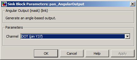
None (Main library). (See Section 1.3, “Licensed Features”.)
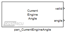
The pan_CurrentEngineAngle block retrieves the current angle of the crankshaft wheel encoder, relative to crank zero degrees (see Section 7.1.3, “Crankshaft zero degrees”). The retrieved value is taken from the angle clock, which is an estimate of crank decoding and position identification process (Section 7.1.4, “Angle clock”).
Set to zero when the software cannot provide an engine angle (for instance, the ECU has not synchronised to the crankshaft wheel), set to one when the outport angle is valid.
Value type: Boolean The estimated angle of the engine taken from the angle clock.
Range: [0, 360) ° crank, for a two-stroke engine
Range: [0, 720) ° crank, for a four-stroke engine
Resolution: at least 0.1 degreesValue type: Real
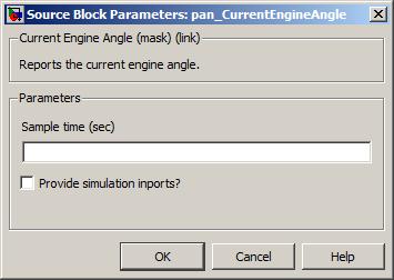
None (Main library). (See Section 1.3, “Licensed Features”.)
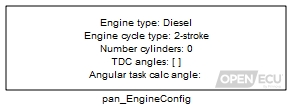
The pan_EngineConfig block specifies the engine cycle type (two-stroke or four-stroke), the TDC-firing angles for each cylinder and the relative angle to TDC-firing at which to trigger the TDC-calculation event. See Section 7.2.2, “Cylinder TDC-firing angles” for details on how the TDC-firing angle is derived from crank zero degrees, and see Section 7.2.3, “Cylinder TDC-calculation application events” for details on the TDC-calculation event.
The block triggers the TDC-calculation event in one of two ways:
Through an asynchronous function-call trigger outport. The output is enabled by ticking the Provide TDC calculation trigger? mask parameter. When the TDC-calculation angle for a cylinder is reached, the function-call trigger occurs. The subsystem attached to the function-call trigger runs with a task priority higher than the application's periodic tasks. See Table 4.8, “Library and application tasks” for an overview of the ECU's tasks.
When using this method, ensure the configuration set option Angular rate functionality (deprecated) is unticked (see the next method and also Section 4.3.4, “Configuration options”).
By adjusting the quickest periodic application rate to run each time a TDC-calculation event occurs. This is an older method and has some incompatibilities with Simulink, both in simulation and on target. In particular, Simulink's task timing is not always correct when running on target.
Warning
This method is deprecated and should not be used. Support cannot be provided for the incompatibilities that this method causes. Use the asynchronous function-call trigger method instead.
As an example, take a symmetrical four stroke four cylinder engine with a 12-1 patterned crankshaft trigger wheel.
Relative to crank zero degrees, the TDC-firing angles for the cylinders in firing order are 46° (cylinder 1), 226° (cylinder 3), 406%deg; (cylinder 2) and 586° (cylinder 4). The application will perform some calculations for each cylinder and 90° prior to TDC-firing is deemed sufficient time to perform those calculations at the highest engine speed plus some margin. Then the parameters to the pan_EngineConfig block would be:
| Engine cycle type: | 4-stroke | ||
| TDC firing angles: | [ 46, 406, 226, 586 ] (given in cylinder order, not firing order) | ||
| TDC calculation angle: | -90 (negative angle BTDC-firing, positive angle ATDC-firing) | ||
| Provide TDC calculation trigger?: | Ticked |
In response, the trigger outport, representing the TDC-calculation events described in more detail in Section 7.2.3, “Cylinder TDC-calculation application events”, is activated by the ECU at 676° (cylinder 1), 136° (cylinder 3), 316° (cylinder 2) and 496° (cylinder 4).
An asynchronous function-call output that triggers an event TDC calculation angle degrees before or after a cylinder's TDC-firing angle.
Value type: Async-function-call
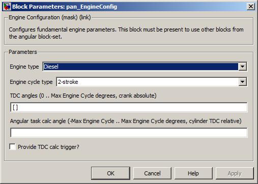
Specifies the expected type of engine to configure the application. The selection of engine type is dependent on the target ECU hardware selected in the put_Identification block. Note that this mask parameter is no longer actively used by the ECU and will be removed in a future version of OpenECU.
Note
If more than 8 cylinders are configured, the engine type must be set to Diesel and the spark functions will not be available.
- Diesel
Configure application for a direct injection type engine (see Section 7.5.2, “Direct injection”).
Supported by: M220, M221, M250 and M670.
- Diesel with spark
Configure application for a sparked direct injection type engine (see Section 7.5.2, “Direct injection” and Section 7.6, “Scheduling coil outputs”).
Supported by: M220, M221, M250 and M670.
- Gasoline (port injection)
Configure application for a port injection type engine (see Section 7.5.1, “Port injection”).
Supported by: M220, M221 and M670.
Value type: List Calibratable: No Specifies whether the engine is four-stroke or two-stroke.
Value type: List Calibratable: No Specifies a vector of values defining the angle of each cylinder's TDC-firing event relative to crank zero degrees.
The vector is specified in cylinder order (and hence the firing order can be derived). The TDC-firing angles must be separated by spaces and enclosed within square brackets, e.g. [90 630 270 450]. The number of entries in the field specifies the number of cylinders.
Size: [1, 6] for M220 and M250
Size: [1, 10] for M221
Size: [1, 12] for M670
Range: [0, 360) ° crank, for a two-stroke engine
Range: [0, 720) ° crank, for a four-stroke engineValue type: List Calibratable: Yes, offline Specifies the angle in degrees relative to TDC-firing when the TDC-calculation trigger for each cylinder is activated (a positive value denotes an angle after TDC-firing, a negative value before TDC-firing). The parameter is a single value and applies to all cylinders.
Range: [-360, 360) ° crank, for a two-stroke engine
Range: [-720, 720) ° crank, for a four-stroke engineValue type: Real Calibratable: Yes, offline Provide TDC calculation trigger?
Tick to enable the asynchronous function-call trigger for TDC-calculation events (recommended), untick to use the quickest periodic application rate for TDC-calculation events (deprecated).
Value type: Boolean Calibratable: No
None (Main library). (See Section 1.3, “Licensed Features”.)
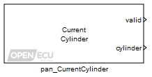
The pan_CurrentCylinder block retrieves the current cylinder identifier of the engine from the ECU. The cylinder identifier is updated whenever a new TDC-calculation angle is reached. See Section 7.2, “Engine TDC-firing events” for a definition of TDC-calculation. The application specifies the TDC-calculation angle using a pan_EngineConfig block.
Set to zero when the ECU cannot provide an engine cylinder (for instance, the ECU has not synchronised to the crankshaft wheel encoder), set to one when the outport cylinder is valid.
Value type: Boolean The current cylinder of the engine.
Range: [1, n]
where n is the number of cylinders specified by the pan_EngineConfig block.Value type: Integer
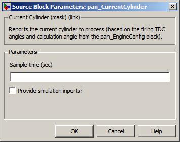
The periodicity of the block execution.
Range: [0.001, 3600] seconds
Value type: Real Calibratable: No Tick to enable inports sim_valid and sim_cylinder.
Value type: Boolean Calibratable: No
None (Main library). (See Section 1.3, “Licensed Features”.)
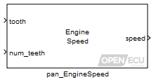
The pan_EngineSpeed block provides the rotational speed of the engine, derived from the primary crankshaft wheel. The ECU continually records the time of arrival for each primary crankshaft wheel tooth. The block uses these timestamps to calculate engine speed. The Type mask parameter selects the speed calculation output by the block.
Only used under simulation. Under simulation, the value of this inport is passed through to outport speed.
Range: [0, 10000] rpm
Value type: Real The cylinder to return the processed tooth rangespeed calculation. Only used when Type is set to Tooth range (relative).
Range: [1, n]
where n is the number of cylinders specified by the pan_EngineConfig block.Value type: Integer The engine tooth identifier used in combination with the num_teeth inport to calculate engine speed, based on the mask parameter Type.
- Tooth range (absolute)
The first engine tooth to be used in the engine speed calculation. See Section 7.2.5, “Engine tooth identification” for a description of engine tooth identifiers. If the given tooth is out of range, the tooth value will be clipped to the range before engine speed is calculated.
Range: [1, n] tooth identifier, two stroke
Range: [1, n*2] tooth identifier, four stroke
where n is the number of physical crank teeth as specified in the pan_CrankWheelConfig block.- Tooth range (relative)
A crank tooth relative to the cylinder's TDC-firing angle (tooth), where 0 is the closest TDC-firing tooth, -1 the proceeding tooth, and so on. Extra teeth in sync points are ignored. If the given tooth is out of range, the tooth value will be clipped to the range before engine speed is calculated.
Range: (-n, 0] tooth identifier, two stroke
Range: (-n*2, 0] tooth identifier, four stroke
where n is the number of physical crank teeth as specified in the pan_CrankWheelConfig block.
Value type: Integer Used in combination with the tooth inport to calculate engine speed. The number of crank teeth after inport tooth to be included as part of the engine speed calculation. The engine speed calculation is based on the time difference between the detection of these teeth. If the given tooth is out of range, the tooth value will be clipped to the range before engine speed is calculated.
Range: [1, n) tooth identifier, two stroke
Range: [1, n*2) tooth identifier, four stroke
where n is the number of physical crank teeth as specified in the pan_CrankWheelConfig block.Value type: Integer
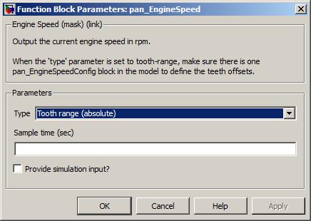
A drop down to specify the speed calculation to perform. The selection of type is dependent on the target ECU hardware selected in the put_Identification block.
- Per cylinder
The speed as measured between two adjacent cylinder TDC-calculation events.
- Per engine revolution
The average speed of the last two 360° revolutions of the primary crankshaft wheel (i.e. every 720° crank, regardless of whether the engine type is four-stroke or two-stroke).
If the ECU has recorded one crank revolution but not yet two, then the speed is averaged over one revolution. This allows the application to retrieve a per-engine-revolution value as quickly as possible but without having to know how many crankshaft revolutions have so far occurred.
- Per tooth
The speed as measured from the time between the last two primary crankshaft wheel teeth. When calculating a speed across a crankshaft sync point, the block adjusts the speed as if there were physical teeth present in the case of missing teeth, or as if there was no physical teeth present in the case of an extra tooth.
- Tooth range (absolute)
The average speed measured between two of the primary crankshaft wheel teeth (specified through inports tooth and num_teeth). The teeth are interpreted as relative to crank zero degrees, see Section 7.2.5, “Engine tooth identification” for further details.
For crankshaft wheels with missing teeth sync points, the time that the missing teeth would have occurred is not estimated and is treated the same as the last physical tooth prior to the missing region sync point. If requesting the engine speed based on missing teeth only, the block outputs zero.
For crankshaft wheels with extra teeth sync points, the time of any extra teeth is not recorded and is treated the same as the last physical tooth prior to the extra tooth sync point. If requesting the engine speed based on extra teeth only, the block outputs zero.
- Tooth range (relative)
The average speed measured between two primary crankshaft wheel teeth (specified through inports tooth and num_teeth). The teeth are interpreted relative to each cylinder's TDC-firing angle.
For crankshaft wheels with missing teeth sync points, the time that the missing teeth would have occurred is not estimated and is treated the same as the last physical tooth prior to the missing region sync point. If requesting the engine speed based on missing teeth only, the block outputs zero.
For crankshaft wheels with extra teeth sync points, the time of any extra teeth is not recorded and is treated the same as the last physical tooth prior to the extra tooth sync point. If requesting the engine speed based on extra teeth only, the block outputs zero.
Value type: List Calibratable: No The periodicity of the block execution.
Range: [0.001, 3600] seconds
Value type: Real Calibratable: No Tick to enable inport sim_speed.
Value type: Boolean Calibratable: No
Retrieve the current engine synchronisation mode.
None (Main library). (See Section 1.3, “Licensed Features”.)
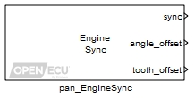
The pan_EngineSync block retrieves the current engine synchronisation mode. The engine synchronisation mode can be changed by the application using the pan_EngineDeclareSync block. A detailed description of the engine synchronisation modes can be found in Section 7.1.9, “Engine synchronisation modes”. For reference, the decoding state values are:
Only used under simulation. Under simulation, the value of this inport is passed through to outport sync.
Value type: Integer
The current engine synchronisation mode. See the description of modes in Section 7.1.9, “Engine synchronisation modes”.
Value type: Integer
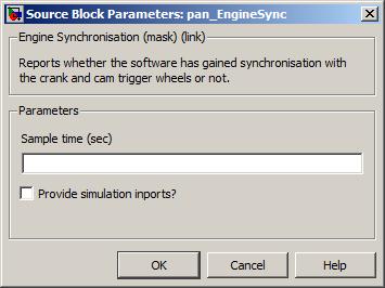
The periodicity of the block execution.
Range: [0.001, 3600] seconds
Value type: Real Calibratable: No Tick to enable inport sim_sync.
Value type: Boolean Calibratable: No
Declare synchronisation with the overall engine position.
None (Main library). (See Section 1.3, “Licensed Features”.)

The pan_EngineDeclareSync block instructs the ECU to switch to a particular engine synchronisation mode. The process is described in Section 7.1.9, “Engine synchronisation modes”.
In short, the ECU will track the crankshaft wheel to achieve crank region synchronisation. The application must then determine the overall engine position, using crank, cam or other indicators, and move to either half or full engine synchronisation (it is not possible for the application to select crank region synchronisation). At any point, the application can force loss of engine synchronisation to deactivate output drivers using the pan_EngineLoseSync block.
Each of the engine synchronisation modes enables different sets of angular functionality. When a function is disabled, input processing ceases and output drivers are turned off.
Table 7.4. Function availability based on engine synchronisation mode
| Engine sync mode | |||||
|---|---|---|---|---|---|
| Function | None | Moving | Region | Half | Full |
| Crank signal processing | Y | Y | Y | Y | Y |
| Cam signal processing | - | - | Y | Y | Y |
| Angle clock | - | - | Y | Y | Y |
| Crank sync point triggers | - | - | Y | Y | Y |
| Cylinder TDC triggers | - | - | Y | Y | Y |
| A/D sampling | - | - | Y | Y | Y |
| Knock sampling | - | - | - | - | Y |
| Port injection | - | Y | - | Y | Y |
| Direct injection | - | - | - | - | Y |
| Sparks | - | - | - | Y | Y |
| Digital outputs | - | - | - | Y | Y |
Set to one of no change (0), full sync (1) or half sync (2) modes. Changing to crank region sync is not supported
If the value of the sync inport matches no change, then ECU makes no change to the current synchronisation process.
If the value of the sync inport matches the current engine synchronisation mode as either half or full, then the ECU ignores the request to change mode.
Value type: Integer The offset to add to crank zero degrees first assigned when crank region synchronisation was found. For example, if the application requests 180 degrees offset after crank synchronisation is found, then the overall engine angle offset is 180 degrees. Subsequently, if the application requests 360 degrees offset, then the overall engine angle offset is 360 degrees (not 180 + 360 degrees).
When loss of engine synchronisation is detected, the ECU clears the engine angle offset to zero.
Range: [-360, 360] ° crank
Resolution: at least 0.1 degreesValue type: Real The offset to add to the engine tooth identifier one, first assigned when crank region synchronisation was found. Like the angle_offset inport, the value is an absolute offset, not an additive offset. Rather than the ECU determine the closest engine tooth to the angle_offset, the application can choose the closest. The ECU expects the tooth offset to match the angle offset and will not operate as expected if the application supplied tooth offset is more than ± 1 tooth from the actual tooth offset.
When loss of engine synchronisation is detected, the ECU clears the engine tooth offset to zero.
Range: [-n, n), for two-stroke
Range: [-n*2, n*2), for four-stroke
where n is the number of teeth on the primary crankshaft wheel.Value type: Real

Force loss of engine synchronisation.
None (Main library). (See Section 1.3, “Licensed Features”.)

The pan_EngineLoseSync block instructs the ECU to lose engine synchronisation. The process is described in Section 7.1.9, “Engine synchronisation modes”. Changing the lose_sync inport from zero to one results in the ECU reverting to the No crank synchronisation mode for the primary crankshaft trigger wheel input, disabling most angular functionality. When a function is disabled, input processing ceases and output drivers are turned off.
Table 7.5. Function availability based on engine synchronisation mode
| Engine sync mode | |||||
|---|---|---|---|---|---|
| Function | None | Moving | Region | Half | Full |
| Crank signal processing | Y | Y | Y | Y | Y |
| Cam signal processing | - | - | Y | Y | Y |
| Angle clock | - | - | Y | Y | Y |
| Crank sync point triggers | - | - | Y | Y | Y |
| Cylinder TDC triggers | - | - | Y | Y | Y |
| A/D sampling | - | - | Y | Y | Y |
| Knock sampling | - | - | - | - | Y |
| Port injection | - | Y | - | Y | Y |
| Direct injection | - | - | - | - | Y |
| Sparks | - | - | - | Y | Y |
| Digital outputs | - | - | - | Y | Y |

Retrieve the current engine tooth identifier from the primary crankshaft position.
None (Main library). (See Section 1.3, “Licensed Features”.)

The pan_CurrentEngineTooth block retrieves the current engine tooth identifier of the primary crankshaft wheel. See Section 7.2.5, “Engine tooth identification” for a description of engine tooth identifiers. Engine tooth identifiers are used when the pan_EngineSpeed block in Tooth range (absolute) and Tooth range (relative) mode.
Set to zero when the ECU cannot provide an engine tooth identifier (for instance, the ECU has not synchronised to the crankshaft wheel encoder), set to one when the outport tooth is valid.
Value type: Boolean The identifying number of the last detected engine tooth of the primary crankshaft wheel encoder. The reported identifier is adjusted by the tooth offset supplied to the pan_EngineDeclareSync block.
Range: [1, n] tooth identifier, two-stroke
Range: [1, n*2] tooth identifier, four-stroke
Where n is the number of physical teeth on the primary crankshaft wheel.Value type: Integer

Configure a set of injector channels for fueling an engine.
None (Main library). (See Section 1.3, “Licensed Features”.)
The pan_InjectorConfig block configures the injector output pins to use for each injection channel, and the injection drive method as outlined in Section 7.5, “Scheduling injector outputs”. The block assigns one injector channel to each cylinder defined by the pan_EngineConfig block. To assign more than one injector channel to a cylinder, see the pan_SingleInjectorConfig block. The application can drive injectors using the pan_Injection_DI and pan_Injection_PI blocks.
Note
For the M250 target, when the Injector Drive parameter is set to Saturating, the pcfg_Config_M250 block must set any injector channels from the Cylinder n injector channel parameter to be PWM.
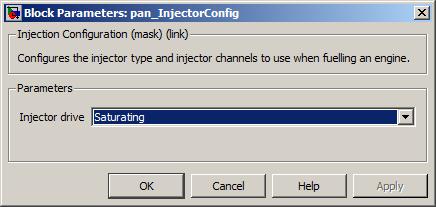
Over time, this mask parameter has become obsolete. As such, this parameter will be removed in a future version of OpenECU. For the moment, always select saturating.
Value type: List Calibratable: No A drop-down selection of injector output channel for cylinder n.
Value type: List Calibratable: No
Configure a single injector output channel for fueling an engine.
None (Main library). (See Section 1.3, “Licensed Features”.)
The pan_SingleInjectorConfig block configures one injector output pin. The injector is identified by a number. The injector identifier is used by the application with the pan_Injection_DI and pan_Injection_PI blocks. With the injector output pin, the block associates a drive type (peak/hold or saturating), an injector pulse type (single pulse or multiple pulse), the output pin that the injector is associated with, and the cylinder identifier the injector is associated with.
The list of available options depends on the choice of target. The number of the cylinder matches its position in the array of TDC-firing angles defined in the pan_EngineConfig block. Number 1 corresponds to the first cylinder in this array, 2 to the second, and so on.
The pan_SingleInjectorConfig block provides a more flexible alternative to the pan_InjectorConfig block, in that there is no automatic association made between cylinders and injectors. In particular, several injectors may be associated with the same cylinder. Unlike the pan_InjectorConfig block, one instance of the pan_SingleInjectorConfig block is required for each angular injector output in the application. The pan_SingleInjectorConfig and pan_InjectorConfig block, must not be used together in the same application.
Note
For the M250 target, when the Injector drive type parameter is set to Saturating then the pcfg_Config_M250 block must set the corresponding injector channel to PWM.
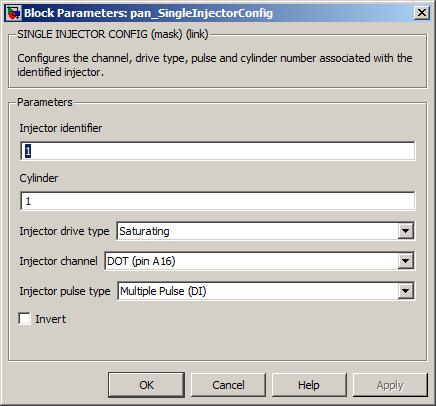
A number to uniquely identify the injector elsewhere in the application.
Value type: Integer Calibratable: No A drop-down selection of channels available for use as injector outputs on the selected target ECU.
Value type: List Calibratable: No Over time, this mask parameter has become obsolete. As such, this parameter will be removed in a future version of OpenECU. For the moment, always select saturating.
Value type: List Calibratable: No A drop-down selection of injector pulse types available for the selected target ECU, i.e. single pulse or multiple pulse.
Value type: List Calibratable: No A number to identify which cylinder this injector is associated with.
Range: [1, n]
where n is the number of cylinders specified by the pan_EngineConfig block.Value type: Integer Calibratable: No
Configures constraints for direct injection.
None (Main library). (See Section 1.3, “Licensed Features”.)
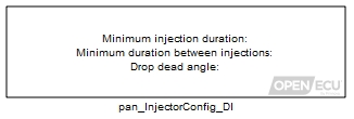
The pan_InjectorConfig_DI block specifies constraints that are applied to the direct injection scheduling. See Section 7.5.2, “Direct injection” for an overview of direct injection and the mask parameters for this block for specific details.
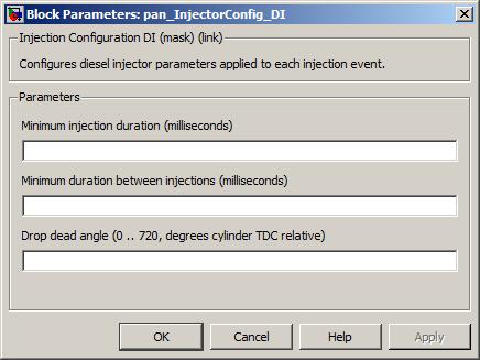
The minimum duration of any injection pulse. Set to zero if a minimum pulse duration is not required. If a requested pulse duration is greater than zero but smaller than this minimum time, the ECU will generate a pulse equal to this minimum time.
The exception to the minimum injection duration is when the injection pulse is cut short due to the Drop dead angle.
Range: [0, 2097] milliseconds
Value type: Real Calibratable: Yes, offline Minimum duration between injections
The minimum time between pulses for a single injector, applied to all injectors. This parameter ensures a minimum time between pulses for an injector and will override the starting angle of a subsequent pulse if necessary.
Range: [0.1, 1.0] milliseconds
Note
Contact Pi Innovo if application requires injector pulse separation outside of the range above.
Value type: Real Calibratable: Yes, offline The drop dead angle applied to all cylinders, relative to the cylinder's TDC-firing angle (positive angles after TDC-firing). The ECU will stop injections at this point on a given cylinder. That is, it will terminate any pulse in progress (regardless of the Minimum injection duration and not schedule any subsequent pulses until the next cylinder cycle.
Range: [0, 360) ° crank, for a two-stroke engine
Range: [0, 720) ° crank, for a four-stroke engine
Resolution: at least 0.1 degreesValue type: Real Calibratable: Yes, offline
Configure the volume to duration conversion for direct injection.
None (Main library). (See Section 1.3, “Licensed Features”.)
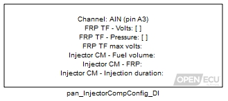
The pan_InjectorCompConfig_DI block configures the fuel rail pressure (FRP) analogue input used to convert injection volume requests into units of time. As described in Section 7.5.2, “Direct injection” just prior to each direct injection pulse is made, the fuel rail pressure analogue input is sampled. Any volume request is converted to a duration using a 2D lookup map. This technique compensates for rapid variation in the fuel rail pressure that may occur after the injection schedule is requested by the application.
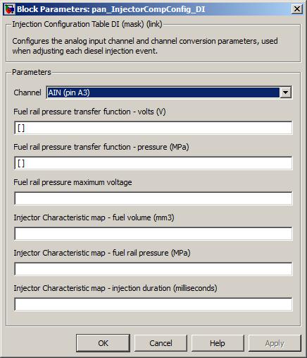
A drop-down selection of analogue input channels to use as the fuel rail pressure input.
Value type: List Calibratable: No Fuel rail pressure transfer function - volts axis
This is the X-axis of the transfer function that converts the fuel rail pressure sensor voltage into engineering units of MegaPascals (MPa). The voltages contained within this axis should range between zero and the voltage specified with the Fuel rail pressure maximum voltage parameter.
Size: [2, 10] elements, for M220, M221 and M250 targets
Size: [2, 15] elements, for M670 targets
Range: [0, Fuel rail pressure maximum voltage] voltsValue type: Real Calibratable: Yes, offline Fuel rail pressure transfer function - pressure
This is the Z-data of the transfer function that converts the fuel rail pressure sensor voltage into engineering units of MegaPascals (MPa).
Size: 1 by [2, 10] elements, for M220, M221 and M250 targets
Size: 1 by [2, 15] elements, for M670 targets
Range: [0, 500] MPaValue type: Real Calibratable: Yes, offline Fuel rail pressure maximum voltage
This is the maximum voltage that can be read by the chosen analogue input Channel before the input saturates, e.g., will be 5.0 on a 0-5v input. This allows the ECU to convert a raw number of A/D converter counts into a voltage.
Range: [0, 24] volts
Value type: Real Calibratable: Yes, offline Injector characteristic map - fuel volume axis
This is the X-axis of the injection duration map.
Size: [2, 10] elements, for M220, M221 and M250 targets
Size: [2, 15] elements, for M670 targets
Range: [0, 512] mm3Value type: Real Calibratable: Yes, offline Injector characteristic map - fuel rail pressure axis
This is the Y-axis of the injection duration map.
Size: [2, 10] elements, for M220, M221 and M250 targets
Size: [2, 15] elements, for M670 targets
Range: [0, 500] MPaValue type: Real Calibratable: Yes, offline Injector Characteristic map - injection duration
This is the data of the injection duration map (Z-data default), the actual injection durations.
Size: [2, 10] by [2, 10] elements, for M220, M221 and M250 targets
Size: [2, 15] by [2, 15] elements, for M670 targets
Range: [0, 1000] milliseconds
Resolution: (floor(max_duration/16.38375ms)+1)*0.2500us for M220, M221 and M250 targets
Resolution: (floor(max_duration/15.88727ms)+1)*0.2424us for M670 targetValue type: Real Calibratable: Yes, offline
Override the fuel rail pressure input used for direct injection.
None (Main library). (See Section 1.3, “Licensed Features”.)
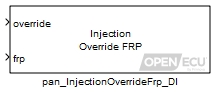
The pan_InjectionOverrideFrp_DI block is used to override the fuel rail pressure input used for direct injection with an arbitrary value (for instance, when the application detects that the fuel rail pressure sensor has failed). When overridden, the ECU will use this value in the injection duration calculations. See Section 7.5.2, “Direct injection” for an overview of direct injection. The application uses the pan_InjectorCompConfig_DI block to select the desired fuel rail pressure input channel and volume to duration conversion table.
Set to one to override the fuel rail pressure override, zero otherwise.
Value type: Boolean The value to override the fuel rail pressure value with, when inport override is set to one.
Range: [0, 500] MPa
Value type: Real
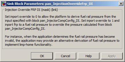
Update the requested schedule of direct injections for one injector channel.
None (Main library). (See Section 1.3, “Licensed Features”.)
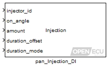
The pan_Injection_DI block updates the direct injection schedule for an injector channel. See the Section 7.5.2, “Direct injection” for an overview of direct injection. In short, the ECU monitors the angle clock and starts injection pulses based on the schedule on_angles. The schedule of pulses can be specified in units of volume or time at run-time, based on the duration_mode inport.
If duration_mode is set to volume mode, the ECU converts a requested volume of fuel from the amount inport into a pulse duration. The ECU samples fuel rail pressure shortly before the injection on angle and uses a map lookup to derive the required injection duration. This is to compensate for very rapid fluctuations in fuel rail pressure that cannot be compensated for in the higher-level strategy, as the correction must be made as late as near to the injection start as possible.
The desired analogue input for fuel rail pressure and related map data and axes are configured with the pan_InjectorCompConfig_DI block.
If duration_mode is set to time mode, the ECU uses the amount inport directly for pulse duration. The ECU will not compensate for fuel rail pressure in this mode.
The injection schedule update takes effect depending on whether the schedule has been started for this cycle or not:
If the application has not previously requested an injection schedule for this injector channel, then the update is applied immediately and the first pulse scheduled. If the angle clock has passed the first pulse's on angle for this cylinder cycle, then the first pulse will be postponed until the next cylinder cycle.
Otherwise, if the first injection pulse from the schedule prior to this update has not yet been generated for this cylinder cycle, then the update is applied immediately and the first pulse rescheduled. If first pulse is in the past compared to the current angle clock, then the first pulse will be postponed until the next cylinder cycle.
Otherwise, if the first injection pulse from the schedule prior to this update has been generated, then the request is buffered and applied at the start of the next cylinder cycle.
Otherwise, if the application makes no further requests to update the injection schedule, then the ECU will repeat the schedule at most 4 times. Once the repeats are completed, the ECU clears the schedule and no further injection pulses are generated until the application requests a new injection schedule.
The ECU supports the generation of up to six injection pulses per cylinder cycle. The on angles are relative to the each cylinder's TDC-firing angle (positive angles after TDC-firing).

Injection pulses are performed on each cylinder according to the requested pulse schedule. If two pulses overlap, the latter pulse will be delayed. (Note that its duration will not be modified.) If this delay then means that the next two pulses overlap, then the next pulse will be delayed too, and so on for the remaining pulses. In effect, the pulses will be shuffled along in time.
The pan_InjectorConfig_DI block is used to define constraints that apply to all injections.

A minimum injection duration that is applied to all pulses can be defined.
A minimum inter-injection delay applied to the durations between all pulses can be defined.
The drop-dead angle for each cylinder is an angle relative to TDC-firing and acts as a final injection cut-off point for a cylinder. That is, any injection in progress at this angle will be terminated and any subsequent injections for that cylinder cycle will not be scheduled.
The drop-dead angle can be set through the pan_InjectorConfig_DI block and remain fixed during application run-time. Or the application can tick this block's Allow updates to drop dead angle for this injector? mask parameter and adjust the drop dead angle during application run-time using the inport dd_angle.
The direct injection functionality is active in full engine synchronisation mode only (see Section 7.1.9, “Engine synchronisation modes” for a description of modes). In any other mode, the ECU forces all injectors off. When the ECU detects loss of engine synchronisation, the injection schedule is cleared and the application must request a new schedule for injections to occur once full engine synchronisation is gained.
The injector identifier number. When the injection was configured using the pan_InjectorConfig block then the injection identifier is the same as the cylinder identifier from that block. When the injection was configured using the pan_SingleInjectorConfig block then the injector identifier is taken from that block.
Range: [1, n]
where n represents the number of supported injector outputs by the selected ECU.Value type: Integer A vector of angles, relative to TDC-firing (positive angles after TDC-firing). Each angle represents the start of an injection pulse. This vector may contain up to six elements and must be the same width as the amount vector. Due to the potential of cyclic wrap-around in the application layer, monotonicity of the vector is not enforced in the platform layer. The platform layer will attempt to schedule all on-angles after the first on-angle in the same cycle by taking the cycle modulus of the relative difference and adding that to the first angle. For correct operation the schedule must have one or two sequences of strictly increasing angles (no repeated values). For example, [0, 90, 180, 270, 360, 450, 540, 630] and [270, 360, 450, 540, 630, 0, 90, 180] are acceptable.
If the drop-dead angle specified by the pan_InjectorConfig_DI block is earlier than the first pulse, the drop-dead angle will be adjusted in cycle increments to be after the first pulse. Any subsequent pulses which occur after that conditioned drop-dead angle will result in no corresponding injection pulse.
Range: [-360, 360) ° crank, for a two-stroke engine
Range: [-720, 720) ° crank, for a four-stroke engine
Resolution: at least 0.1 degreesValue type: Real A vector of pulse volumes or pulse durations depending on the duration_mode inport. This vector may contain up to six elements and must be the same size and ordering as the on_angle inport vector.
Range: [0, 512) mm3 if duration_mode is set to volume
Range: [0, 1000] milliseconds if duration_mode is set to timeNote
The best resolution of injection duration is 0.25 microseconds for M2xx targets and 0.2424 microseconds for M670. Actual resolution of the duration is a function of the maximum duration of all pulses in this schedule request. In the current implementation, granularity doubles every power of two times the maximum timer duration. The maximum timer duration is 16.384 milliseconds for M2xx targets, and 15.887 milliseconds for M670. For example, the M2xx resolution is 0.25 us if the maximum pulse duration is less than 16.384 milliseconds, and the resolution will go to 0.50 us if the maximum pulse duration is between 16.384 us and 32.7675 us, etc.
Value type: Real An additive offset of duration applied to each injection pulse, used to compensate for slight mechanical and electrical differences between injectors.
Range: [-8.192, 8.192] milliseconds
Value type: Real Set to zero to interpret the amount inport in units of volume, set to one to interpret as units of time.
Value type: Boolean The drop dead angle applied to this injector, relative to TDC-firing. The ECU will stop injections at this point on a given cylinder. Available when the Allow updates to drop dead angle for this injector? mask parameter is ticked.
Range: [-360, 360) ° crank, for a two-stroke engine
Range: [-720, 720) ° crank, for a four-stroke engine
Resolution: at least 0.1 degreesValue type: Real
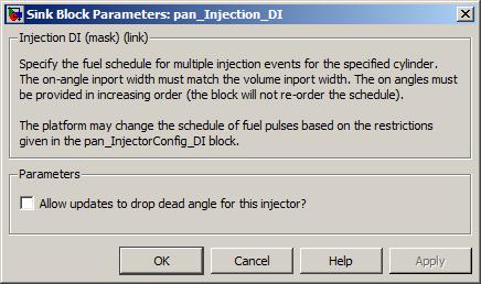
Allow updates to drop dead angle for this injector?
Tick to enable the inport dd_angle.
Value type: Boolean Calibratable: No
Read back direct injection parameters for a given injector.
None (Main library). (See Section 1.3, “Licensed Features”.)
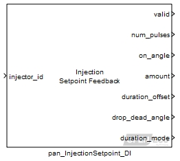
For a given injector, the pan_InjectionSetpoint_DI block reads the injection schedule supplied by the application. The pan_InjectionSetpoint_DI block is used to verify that the data stored in eTPU memory match that which the application intended to write, allowing for checks of eTPU memory faults.
If this function is called while the eTPU is updating internal schedule parameters, it will wait until the eTPU is complete guaranteeing that all the parameters read are from a single schedule.
The injector identifier of the injection schedule to read. When the injection was configured using the pan_InjectorConfig block then the injection identifier is the same as the cylinder identifier from that block. When the injection was configured using the pan_SingleInjectorConfig block then the injector identifier is taken from that block.
Range: [1, n]
where n represents the number of supported injector outputs by the selected ECU.Value type: Integer
One when the data read was successfully and coherently read, zero if a problem occurred.
Value type: Boolean A vector of injection on-angles, relative to TDC-firing, to match the values passed to the pan_Injection_DI block.
Range: [-720, 720] ° crank
Resolution: at least 0.1 degreesNote
The values returned in this vector are the internal representation of the angles. These may differ from the specified values by a modulo to fit into the internal angle range.
Value type: Real A vector of injection amounts to match the values passed to the pan_Injection_DI block.
Range: [0, 512) mm3 if duration_mode is set to volume
Range: [0, 1000] milliseconds if duration_mode is set to timeValue type: Real An additive duration applied to this injector's pulses to match the value passed to the pan_Injection_DI block.
Range: [-8.192, 8.192] milliseconds
Value type: Real Whether the application specified the injection schedule in volume or time, matching the value passed to the pan_Injection_DI block.
Value type: Boolean The drop dead angle as set by the parameter value passed to the pan_InjectorConfig_DI block.
Range: [-720, 720] ° crank
Resolution: at least 0.1 degreesNote
The value passed to the ECU is transformed to be kept with in a valid angle range. This transform cannot be reversed, so the angle is reported with the following transform applied:
on_angle = ((on_angle + 1080°) mod 720°) - 360°
Value type: Real
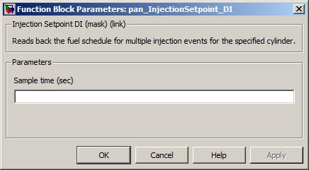
Report feedback for injection events that have already occurred.
None (Main library). (See Section 1.3, “Licensed Features”.)

The pan_InjectionFeedback_DI block reports direct injection events that have already occurred for a selected injector.
The reported information is updated at the end of each direct injection event. If the block iterates while an injection event for the selected injector is on-going, then the application must determine the appropriate index for the vector parameters from the pulse event counter.
A value of 1 specifies that the data read was successfully. A value of 0 indicates that some problem occurred.
Value type: Real A vector of injection starting angles, relative to TDC-firing for the associated cylinder for this injector identifed by inport injector_id to match the values passed to the pan_Injection_DI block.
Size: [1, 6] entries
Range: [-1080, 720] ° crankNote
The value passed to the ECU is transformed to be kept with in a valid angle range. This transform cannot be reversed, so the angle is reported with the following transform applied:
on_angle = ((on_angle + (cylinder's TDC-firing angle) + 1080°) mod 720°) - 360° - (cylinder's TDC-firing angle)
Value type: Real A vector of injection ending angles, relative to TDC-firing for the associated cylinder for this injector identifed by inport injector_id to match the values passed to the pan_Injection_DI block.
Size: [1, 6] entries
Range: [-1080, 720] ° crankNote
The value passed to the ECU is transformed to be kept with in a valid angle range. This transform cannot be reversed, so the angle is reported with the following transform applied:
off_angle = ((off_angle + (cylinder's TDC-firing angle) + 1080°) mod 720°) - 360° - (cylinder's TDC-firing angle)
Value type: Real A vector of injection durations, relative to TDC-firing for the associated cylinder for this injector identifed by inport injector_id to match the values passed to the pan_Injection_DI block.
Size: [1, 6] entries
Range: [0, 1000] millisecondsValue type: Real The number of injection events that have occurred for the injector identifed by inport injector_id.
Range: [0, inf] modulo 8388608
The accumulated fuel flow time of the injector identifed by inport injector_id since the ECU was reset.
Range: [0, inf] modulo 1041204 milliseconds
The accumulated fuel flow volume of the injector identifed by inport injector_id since the ECU was reset. The value of this outport is only valid if the duration_mode inport to the pan_Injection_DI block is set to volume mode.
Range: [0, inf] modulo 2097151 mm3

Specify the duration of the initial injection (the priming fuel pulse).
None (Main library). (See Section 1.3, “Licensed Features”.)

The pan_InitialInjection_PI block sets the duration of the fuel priming pulse which occurs when the engine is first seen to be turning (before crank region synchronisation has been achieved). The purpose of the initial fuel pulse is to ensure there is sufficient fuel in the engine cylinders when the first sparks occur to match the environmental conditions and engine size, making the engine more likely to start.
The initial fuel pulse must be explicitly enabled by inputting a rising edge to the enable inport. Once this is detected, a request to generate an initial pulse is latched and this request is only cleared when the initial pulse starts, i.e. once crank movement has been detected. If the engine stops and then starts again without the ECU losing power, then another initial pulse will only be generated if a further request has been detected by inputting another rising edge to the enable inport. This can be done any time after the previous initial pulse has started.
The duration of the initial fuel pulse is calculated the minimum of (inport flow_time + inport dead_time) and 500 milliseconds. The duration is unaffected by the end of intake angle specified through the pan_Injection_PI block.
Due to the relative timing between sensing the engine starting to turn and the ECU synchronising with the crank trigger wheel which in turn causes scheduled spark events to occur, unburnt fuel can pass through a cylinder into the exhaust. Because unburnt fuel can pass into the exhaust, the initial fuel pulse method is not generally used for emissions related programmes. The initial fuel pulse can be turned off by not using the pan_InitialInjection_PI block, or using the pan_InitialInjection_PI block with a total injection time of zero milliseconds.
The flow time represents the time the injector allows fuel to pass the injector tip.
Range: [0, 500] milliseconds
Value type: Real The dead time represents the time it takes the injector needle to lift and allow fuel to flow.
Range: [0, 500] milliseconds
When the dead time is updated for injector n, it is updated for all injectors, as it is a shared parameter.
Value type: Real A change of input state from 0 to 1 is interpreted as a request for an initial injection pulse. Such a request is latched until the pulse begins.
Value type: Boolean

Set the injector pulse schedule for a cylinder.
None (Main library). (See Section 1.3, “Licensed Features”.)

The pan_Injection_PI block updates the port injection schedule for an injector channel. See the Section 7.5.1, “Port injection” for an overview of port injection. In short, the ECU monitors the angle clock and starts the main injection pulse based on the schedule on_angle. The injection lasts for the requested duration.

The total injection drive signal lasts for inport flow_time + inport dead_time. flow_time and dead_time are individually clipped to their respective ranges. The dead time represents the time it takes the injector needle to lift and allow fuel to flow. The flow time represents the time the injector allows fuel to pass the injector tip.

If the duration of the injection event extends beyond the end_of_intake_angle then the injection pulse is stopped. Usually end_of_intake_angle is configured to occur before the inlet valve closes so that fuel is not left to pool behind the intake valve to be ingested in the next cylinder cycle.

The port injection functionality is active in half and full engine synchronisation mode (see Section 7.1.9, “Engine synchronisation modes” for a description of modes).
In half engine synchronisation mode for a four-stroke engine, injection pulses are generated every 360 degrees, and the on_angle and end_of_intake_angle values are interpreted modulo 360 degrees.
A further inport is available, split_fuel_factor, to determine what fraction of the full flow time to apply. This allows wall-wetting effects to be included more easily when calculating the pulse durations. In this case, the pulse duration is given by:
dead_time + (flow_time x split_fuel_factor)
In half engine synchronisation mode for a two-stroke engine, then injection pulses are generated as if the ECU were in full engine synchronisation mode.
In full engine synchronisation mode for a two or four-stroke engine, injection pulses are generated in full every engine cycle.

When neither half or full engine synchronisation is active, the ECU forces all injectors off (the exception to this rule is the initial fuel pulse which may occur if movement in the crank wheel has been detected but crank region synchronisation has not yet been achieved).
The cylinder to request an injection pulse.
Range: [1, n]
where n is the number of cylinders specified by the pan_EngineConfig block.Value type: Integer The requested start angle for the first main pulse relative to the cylinder's TDC-firing angle (a positive value denotes an angle after TDC-firing). In half engine synchronisation mode, the ECU will generate a second main pulse, starting 360° on from the start of the first main pulse.
Range: [-360, 360) ° crank, for a two-stroke engine
Range: [-720, 720) ° crank, for a four-stroke engineValue type: Real The flow time represents the time the injector allows fuel to pass the injector tip.
Range: [0, 350] milliseconds
Value type: Real The dead time represents the time it takes the injector needle to lift and allow fuel to flow.
Range: [0, 350] milliseconds
When the dead time is updated for injector n, it is updated for all injectors, as it is a shared parameter.
Value type: Real The angle at which to stop any ongoing injection pulse. Must be no more than ± 720 degrees from the start of injection angle inport on_angle.
Range: [-360, 360) ° crank, for a two-stroke engine
Range: [-720, 720) ° crank, for a four-stroke engine
Resolution: at least 0.1 degreesNote
If crank sync has not been achieved, then this value will be that of negative the TDC firing angle.
Value type: Real The fraction of the flow-time to use when half engine synchronisation mode is active.
Range: [0, 1)
Value type: Real

Update the port injection schedule for a cylinder.
None (Main library). (See Section 1.3, “Licensed Features”.)

The pan_Injection_PI block schedules a main pulse (and possibly a second main pulse if half engine synchronisation mode is active). Once scheduled, the start angle and duration of the pulse can be modified in response to transient conditions using pan_UpdateInjection_PI block.
The pan_UpdateInjection_PI block can change the start angle of the main injection pulse if the main injection pulse for the current cylinder cycle has not started.
The pan_UpdateInjection_PI block can change the duration of the main injection pulse if the main pulse has not started or if the pulse has not completed. This may result in a contracted or extended pulse.
The pan_UpdateInjection_PI block can generate a post injection pulse if the main pulse has completed and the requested duration is larger than the already delivered pulse. The block may generate more than one post pulse if invoked more than once during the engine cycle. Generation of post pulses is controlled through the enable_post_pulses inport.

Updates to the port injection schedule can be disabled through the enable_update inport.
When neither half or full engine synchronisation is active, the ECU forces all injectors off (the exception to this rule is the initial fuel pulse which may occur if movement in the crank wheel has been detected but crank region synchronisation has not yet been achieved).
Set to one to allow the block to update the injector schedule, zero otherwise.
Value type: Boolean Set to one to allow post pulses to occur, zero otherwise.
Value type: Boolean The cylinder to request an injection pulse.
Range: [1, n]
where n is the number of cylinders specified by the pan_EngineConfig block.Value type: Integer The requested start angle for the first main pulse relative to the cylinder's TDC-firing angle (a positive value denotes an angle after TDC-firing). In half engine synchronisation mode, the ECU will generate a second main pulse, starting 360° on from the start of the first main pulse.
If the injector has been scheduled for a main pulse but has not yet started the main pulse for the current cylinder cycle, the start angle will be adjusted if there is enough time to do so.
Range: [-360, 360) ° crank, for a two-stroke engine
Range: [-720, 720) ° crank, for a four-stroke engineValue type: Real The flow time represents the time the injector allows fuel to pass the injector tip.
If the injector has been scheduled for a main pulse but has not yet started, or if the main pulse has started but not completed, then the main pulse duration will be adjusted accordingly. If the main pulse has completed and this request is larger than the already delivered fuel, a post pulse will be generated for the difference between the request and the delivered fuel.
Range: [0, 350] milliseconds
Value type: Real The dead time represents the time it takes the injector needle to lift and allow fuel to flow.
Range: [0, 350] milliseconds
Value type: Real The fraction of the flow-time to use when unsynchronised with the cam wheel.
Range: [0, 1)
Value type: Real

Read back port injection parameters for a given injector.
None (Main library). (See Section 1.3, “Licensed Features”.)

For a given injector, the pan_InjectionSetpoint_PI block reads the port injection schedule supplied by the application. The pan_InjectionSetpoint_PI block is used to verify that the data stored in eTPU memory match that which the application intended to write, allowing for checks of eTPU memory faults.
If this function is called while the eTPU is updating internal schedule parameters, it will wait until the eTPU is complete guaranteeing that all the parameters read are from a single schedule.
The cylinder identifier of the injection schedule to read.
Range: [1, n]
where n is the number of cylinders specified by the pan_EngineConfig block.Value type: Integer
One when the data read was successfully and coherently read, zero if a problem occurred.
Value type: Boolean The injection on angle, relative to TDC-firing, to match the values passed to the pan_Injection_PI block.
Range: [-720, 720] °
Resolution: at least 0.1 degreesValue type: Real The duration of injection flow time to match the value passed to the pan_Injection_PI block.
Range: [0, 350] milliseconds
Value type: Real The duration of injection dead time to match the value passed to the pan_Injection_PI block.
Range: [0, 350] milliseconds
Value type: Real The angle at which to turn injector off to match the value passed to the pan_Injection_PI block.
Range: [-360, 360) ° crank, for a two-stroke engine
Range: [-720, 720) ° crank, for a four-stroke engine
Resolution: at least 0.1 degreesNote
If crank sync has not been achieved, then this value will be that of negative the TDC firing angle.
Value type: Real The fraction of the flow time used when in split-fuel mode to match the value passed to the pan_Injection_PI block.
Range: [0, 1)
Value type: Real

Report feedback for port injection events that have already occurred.
None (Main library). (See Section 1.3, “Licensed Features”.)

The pan_InjectionFeedback_PI block reports information about injection events that have already occurred for a selected cylinder. At the end of each port injection pulse, the ECU increments a counter of requested pulses and increments an accumulator of total injection flow time.
Whenever the ECU attempts to generate a pulse, the feedback information is updated. If the ECU cannot generate a pulse due to an electrical fault, or if the ECU partially generates a pulse due to the pulse schedule being cut short during the dead-time portion, the pulse count is incremented regardless.
The accumulated flow time does not include any of the dead-time portions, but does include priming/initial, main or post pulses, and correctly accounts for a pulse that is cut short due to the drop-dead angle.
The feedback information is incremented using modulo arithmetic. The application must iterate the pan_InjectionFeedback_PI block frequently enough to avoid inaccurate results due to the modulo operation.
The cylinder of the injection events.
Range: [1, n]
where n is the number of cylinders specified by the pan_EngineConfig block.Value type: Real
A value of 1 specifies that the data read was successfully and coherently read. A value of 0 indicates that some problem occurred.
Value type: Real The number of injection events that have occurred for this cylinder since the ECU was reset.
Range: [0, inf] modulo 8388608
The accumulated flow time since the ECU was reset.
Range: [0, inf] modulo 1041204 milliseconds

Configure the parameters used to sample a knock sensor.
None (Main library). (See Section 1.3, “Licensed Features”.)
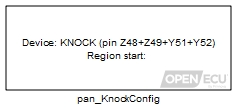
The pan_KnockConfig block configures the knock processing functionality and sets the earliest starting angle of any knock detection window relative to each cylinder's TDC-firing angle.
Note
The angle sense differs from most other angular blocks. A positive value denotes an angle before TDC-firing, and a negative value denotes an angle after TDC-firing. See Section 7.2.1, “Relative angles to TDC-firing” for more).
See the Section 7.4, “Knock sensor processing” for an overview of knock sensor processing. In short, the application schedules a sample window in which to process a knock sensor signal using the pan_KnockDetectionWindow block. The parameters that can be adjusted for knock processing are set by the application using the pan_KnockFilter_Hip901x block. Shortly after the end of each sample window, the ECU completes knock signal processing and buffers the result which can be retrieved by the application using the pan_KnockFeedback block.
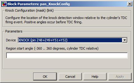
The HIP901x device, as identified by the input pins it is associated with.
Value type: List Calibratable: No The earliest starting angle of any knock detection window relative to a cylinder's TDC-firing angle (positive angles before TDC-firing).
Range: [360, -360] ° crank
Resolution: at least 0.1 degreesValue type: Real Calibratable: Yes, offline
Schedule the angular region used to process a knock sensor signal for a cylinder.
None (Main library). (See Section 1.3, “Licensed Features”.)
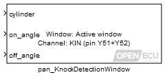
The pan_KnockDetectionWindow block schedules sampling and filtering of a knock transducer sensor signal in regions relative to each cylinder's TDC-firing event.
Note
The angle sense differs from most other angular blocks. A positive value denotes an angle before TDC-firing, and a negative value denotes an angle after TDC-firing. See Section 7.2.1, “Relative angles to TDC-firing” for more).
The filter characteristics are specific to the knock signal processing device. For the HIP901x family of knock signal processors, the pan_KnockFilter_Hip901x block is used to configure these settings. The result of the sampling and filtering is provided by the pan_KnockFeedback block.

The above diagram shows a knock window relative to a cylinder's TDC-firing point, where the knock transducer sensor signal is sampled and filtered. The knock window is chosen to centre on a cylinder's knocking event and is used to exclude other engine noise such as ignition and valve closing events.
For each cylinder, there is a region around the cylinder's TDC-firing point within which a knock window can be generated.
If the start angle of the knock window lies outside the cylinder's region, or if the end angle occurs before start angle or if the window is too small to be generated reliably, no knock window is generated for that cylinder.
If the end angle extends into the next cylinder's region, the end angle is clipped so that it does not cause the knock window to extend into the next cylinder's region.
The result of the knock filtering is made available shortly after the end of the knock window via the pan_KnockFeedback block.
Knock signal processing is active in full engine synchronisation mode and disabled in other modes.
The cylinder to request a knock detection window.
Range: [1, n]
where n is the number of cylinders specified by the pan_EngineConfig block.Value type: Integer Start angle of the knock detection window relative to the cylinder's TDC-firing angle (positive angles before TDC-firing). The block folds the angle into the range [0, 720)°.
Value type: Real End angle of the knock detection window relative to the cylinder's TDC-firing angle (positive angles before TDC-firing). The block folds the angle into the range [0, 720)°.
Value type: Real
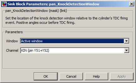
A drop-down list of window types. Some targets support the sampling of a reference window in addition to an active window.
Value type: List Calibratable: No The input pin(s) sourcing the signal to measure. Note that this mask parameter is currently unused and is only provided for future expandability. The channel is selected when the pan_KnockFilter_Hip901x block iterates. This also means that only one knock channel window can be set at a time.
Value type: List Calibratable: No
Retrieve the result of the last processed knock signal for a cylinder.
None (Main library). (See Section 1.3, “Licensed Features”.)
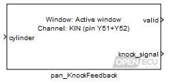
The pan_KnockFeedback blocks retrieves the result of the last processed knock signal for a cylinder. When the knock sensor signal was processed, and the parameters used in processing, are set by the application using the pan_KnockDetectionWindow and pan_KnockFilter_Hip901x blocks.
Knock signal processing is active in full engine synchronisation mode and disabled in other modes. When the ECU is not in full engine synchronisation mode, the knock processing result is forced to zero.
The cylinder to retrieve the processed knock result.
Range: [1, n]
where n is the number of cylinders specified by the pan_EngineConfig block.Value type: Integer The value of this inport is passed to the knock_signal output under simulation.
Value type: Real
The result of the last processed knock signal for the cylinder if the valid outport is one, zero otherwise.
Range: [0, 5] volts
Value type: Real Set to one if the processed knock signal is valid, zero otherwise. Causes of valid being zero include: lack of full engine synchronisation; requested cylinder is outside the number of cylinders configured (see the pan_EngineConfig block), knock is not configured by the application (a pan_KnockConfig block does not exist in the application), or if the application sets the knock window starting angle in the pan_KnockDetectionWindow block too close to the start of the knock region window specified with the pan_KnockConfig block, where too close is defined as the two angles occurring within 223 microseconds at the current engine RPM.
Value type: Boolean
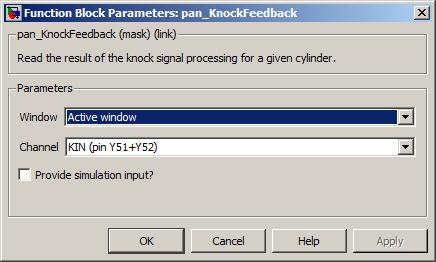
A drop-down list of window types. Some targets support the sampling of a reference window in addition to an active window.
Value type: List Calibratable: No The input pin sourcing the signal to measure. Note that this mask parameter is currently unused and is only provided for future expandability. The channel is selected when the pan_KnockFilter_Hip901x block iterates. This also means that only one knock channel can be read at a time, and the data will come from the channel of the last iterated pan_KnockFilter_Hip901x block.
Value type: List Calibratable: No Tick to enable inport sim_knock_signal.
Value type: Boolean Calibratable: No
Update the scheduled knock signal filtering parameters for a cylinder for the HIP901x family of engine knock signal processors.
None (Main library). (See Section 1.3, “Licensed Features”.)
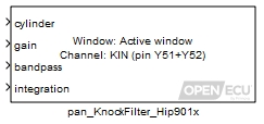
The pan_KnockFilter_Hip901x block sets the HIP901x device signal processing parameters to be applied to the knock transducer signal when it is sampled. The sensor sampling region is set by the application using the pan_KnockDetectionWindow block. The result of the filtering is provided by the pan_KnockFeedback block.
A simplified view of the knock signal processing stages is given in the following block diagram:

The knock signal to process is first selected from two differential inputs, as selected by the application using the pan_KnockConfig block. The device responsible for detecting knock can process just one sensor at a time.
The knock signal is then passed through a 3rd order anti-aliasing filter. This filter is required to have no more than 1dB attenuation at 20kHz (highest frequency of interest) and a minimum attenuation of 10dB at 180kHz.
The knock signal is then passed through a gain stage to compensate knock energies if needed.
The knock signal is then passed through a band-pass filter to detect the frequencies of interest. The filter frequency is established by the characteristics of the particular engine and transducer.
The knock signal is then passed through a full wave rectifier before being passed into an integrator stage, the output of which can be monitored for knock. Integration is towards the positive supply when a knock signal is present.
Knock signal processing is active in full engine synchronisation mode and disabled in other modes. When the ECU is not in full engine synchronisation mode, the knock processing result is forced to zero.
The cylinder to set the knock filter parameters.
Range: [1, n]
where n is the number of cylinders specified by the pan_EngineConfig block.Value type: Integer Gain applied to the knock transducer signal for a specific cylinder.
Range: [0.111, 2] unitless
Value type: Real Bandpass centre frequency applied to the knock transducer signal for a specific cylinder.
Range: [1.22, 19.98] kHz
Value type: Real Integration time constant applied to the knock transducer signal for a specific cylinder.
Range: [40, 600] microseconds
Value type: Real
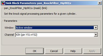
The values of the gain, bandpass and integrator inports are quantised by the knock processing as given in the table below. Input values are rounded to the nearest available discrete value. Out of range input values are clipped to range.
| Gain | Bandpass | Integrator |
|---|---|---|
| kHz | microseconds | |
| 2.000 | 1.22 | 40 |
| 1.882 | 1.26 | 45 |
| 1.778 | 1.31 | 50 |
| 1.684 | 1.35 | 55 |
| 1.600 | 1.40 | 60 |
| 1.523 | 1.45 | 65 |
| 1.455 | 1.51 | 70 |
| 1.391 | 1.57 | 75 |
| 1.333 | 1.63 | 80 |
| 1.280 | 1.71 | 90 |
| 1.231 | 1.78 | 100 |
| 1.185 | 1.87 | 110 |
| 1.143 | 1.96 | 120 |
| 1.063 | 2.07 | 130 |
| 1.000 | 2.18 | 140 |
| 0.944 | 2.31 | 150 |
| 0.895 | 2.46 | 160 |
| 0.850 | 2.54 | 170 |
| 0.810 | 2.62 | 180 |
| 0.773 | 2.71 | 200 |
| 0.739 | 2.81 | 220 |
| 0.708 | 2.92 | 240 |
| 0.680 | 3.03 | 260 |
| 0.654 | 3.15 | 280 |
| 0.630 | 3.28 | 300 |
| 0.607 | 3.43 | 320 |
| 0.586 | 3.59 | 360 |
| 0.567 | 3.76 | 400 |
| 0.548 | 3.95 | 440 |
| 0.500 | 4.16 | 480 |
| 0.471 | 4.39 | 520 |
| 0.444 | 4.66 | 560 |
| 0.421 | 4.95 | 600 |
| 0.400 | 5.12 | |
| 0.381 | 5.29 | |
| 0.364 | 5.46 | |
| 0.348 | 5.66 | |
| 0.333 | 5.90 | |
| 0.320 | 6.12 | |
| 0.308 | 6.37 | |
| 0.296 | 6.64 | |
| 0.286 | 6.94 | |
| 0.276 | 7.27 | |
| 0.267 | 7.63 | |
| 0.258 | 8.02 | |
| 0.250 | 8.46 | |
| 0.236 | 8.95 | |
| 0.222 | 9.50 | |
| 0.211 | 10.12 | |
| 0.200 | 10.46 | |
| 0.190 | 10.83 | |
| 0.182 | 11.22 | |
| 0.174 | 11.65 | |
| 0.167 | 12.10 | |
| 0.160 | 12.60 | |
| 0.154 | 13.14 | |
| 0.148 | 13.72 | |
| 0.143 | 14.36 | |
| 0.138 | 15.07 | |
| 0.133 | 15.84 | |
| 0.129 | 16.71 | |
| 0.125 | 17.67 | |
| 0.118 | 18.76 | |
| 0.111 | 19.98 |
Configure a set of spark channels for running an engine.
None (Main library). (See Section 1.3, “Licensed Features”.)
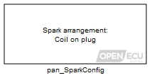
The pan_SparkConfig block configures a set of spark output channels and the drive method (coil-on-plug or wasted spark). The drive method results in different spark pulse sequences depending on the engine synchronisation mode (see Section 7.1.9, “Engine synchronisation modes” for an overview of modes).
Coil-on-plug — associates one spark output pin with one spark coil. In full engine synchronisation mode, the ECU generates one spark pulse. In half engine synchronisation mode, the ECU will either generate no spark pulses, or generate two spark pulses per engine cycle, depending on the 4-stroke 360 degree sparks in half engine sync mode? mask parameter.
Generating two spark pulses per engine cycle helps start the engine when the application does not know which half of the engine cycle is active. This mode of spark generation is similar to wasted spark, and indeed half of the sparks are wasted on average, but unlike the wasted spark mode, there must be one coil for each cylinder.
Wasted spark — associates one spark output pin with two spark coils. Each spark coil corresponds to one engine cylinder. The wasted spark option can be used to run a four-stroke engine that have evenly spaced TDC-firing angles with half as many spark output pins.
For the M250 target, the application must use the pcfg_Config_M250 block to set any spark channels from the Cylinder n spark channel mask parameter to be PWM.
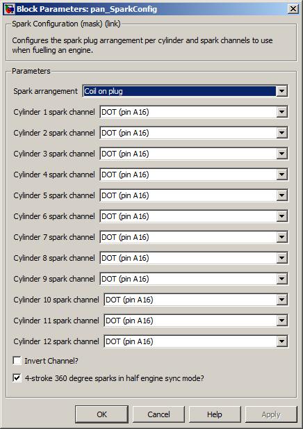
The required spark arrangement type, either coil-on-plug (one spark output pin per coil per cylinder) or wasted spark (one spark output pin for two coils, one coil per cylinder).
Value type: List Calibratable: No A drop-down selection of spark output channel for cylinder n.
Value type: List Calibratable: No Select to invert the spark output polarity.
Value type: Boolean Calibratable: No 4-stroke 360 degree sparks in half engine sync mode?
Whether to emit sparks every 360 degrees until full engine synchronisation has been obtained. This can aid quicker engine starting for inline engines, but may be unsuitable for “V” engines if shared-coil wasted spark is also in use.
Value type: Boolean Calibratable: No
Update the requested schedule of spark pulses for one spark channel.
None (Main library). (See Section 1.3, “Licensed Features”.)
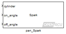
The pan_Spark block schedules a spark pulse for a cylinder. See Section 7.6, “Scheduling coil outputs” for an overview of driving coils. In short, the ECU monitors the angle clock and generates a spark pulse based on the schedule's on_angle and off_angle, relative to a cylinder's TDC-firing angle.
Note
The angle sense differs from most other angular blocks. A positive value denotes an angle before TDC-firing, and a negative value denotes an angle after TDC-firing. See Section 7.2.1, “Relative angles to TDC-firing” for more).
The generation of one or more spark pulses is based on the current engine synchronisation mode and the configuration applied by the application. See Section 7.1.9, “Engine synchronisation modes” for an overview of synchronisation modes.
In full engine synchronisation mode with the wasted spark option disabled, the ECU generates one pulse per engine cycle per spark output pin.
In full engine synchronisation mode with the wasted spark option enabled, the ECU generates two pulses per engine cycle per spark output pin. The wasted spark option can be used to run a four-stroke engine that have evenly spaced TDC-firing angles with half as many spark output pins.
In half engine synchronisation mode with the 360 degree spark option disabled, the ECU will generate no spark pulses.
In half engine synchronisation mode with the 360 degree spark option enabled and the wasted spark option disabled, the ECU will generate two pulses per engine cycle per spark output pin. The spark schedule is repeated every 360 degrees.
In half engine synchronisation mode with the 360 degree spark option enabled and the wasted spark option enabled, the ECU will generate two pulses per engine cycle per spark output pin. The spark schedule with the later angle is chosen to be repeated every 360 degrees.
Note
On an evenly spaced TDC-firing angle engine, there is unlikely to be much of a difference between the two cylinder spark schedule requests. But for an unevenly spaced TDC-firing angle engine, it isn't possible to know which of two cylinder schedules to use for a single spark output pin. So the ECU chooses the last of the two schedules as being too late in one cylinder will give poor-torque firing but being too early in other cylinder may result in backwards firing.
For this reason, neither wasted spark nor 360 degree spark options are recommended for an asymmetrical engine.


In all cases, if the application requests a change to the spark schedule using the pan_Spark block, then the ECU takes one of two actions. If a spark pulse is being generated when the application makes the new schedule request, then the new request is buffered for the next cycle, but if a spark pulse is not being generated then the new request is used immediately. In the case where the new schedule is used immediately, this will result in a second spark pulse for the engine cycle if the new schedule starting angle is in the future.
If the application makes no further requests to update the spark schedule, then the ECU will repeat the schedule at most 4 times. Once the repeats are completed, the ECU clears the schedule and no further spark pulses are generated until the application requests a new spark schedule.
The spark functionality is active in half and full engine synchronisation mode only (see Section 7.1.9, “Engine synchronisation modes” for a description of modes). In any other mode, the ECU forces all spark outputs off.
Note
Unlike other angular functionality, when an application updates the spark schedule, the ECU will wait for the existing spark pulse to complete (if one is active) and then immediately schedule the update. If the update can be scheduled in the same cylinder cycle, then it will be, otherwise the update will be scheduled for the next cylinder cycle. For this reason, it may be preferable to update the spark schedule using the TDC-calculation trigger, rather than periodically.
Note
If the ECU has electrical monitoring and protection features, that can automatically turn off a spark output in the event of over-current (for example), then leaving the spark output on for too long may lead to advanced spark timing when the ECU turns the spark output off before the end angle has been reached to protect the electronics.
The cylinder on which to schedule the spark pulse.
Range: [1, n]
where n is the number of cylinders specified by the pan_EngineConfig block.Value type: Integer The starting angle of the spark pulse, relative to TDC-firing (positive angle is before TDC-firing).
Range: [-360, 360) ° crank, for a two-stroke engine
Range: [-720, 720) ° crank, for a four-stroke engineValue type: Real The ending angle of the spark pulse, relative to TDC-firing (positive angle is before TDC-firing).
Range: [-360, 360] ° crank, for a two-stroke engine
Range: [-720, 720] ° crank, for a four-stroke engineValue type: Real
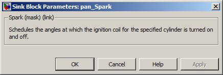
Retrieve spark pulse information for a given cylinder.
None (Main library). (See Section 1.3, “Licensed Features”.)

The pan_SparkFeedback block retrieves information about spark events that have occurred for a specific cylinder. At the end of each spark pulse, the ECU increments a counter of requested pulses and captures the requested off angle of the pulse.
When the ECU attempts to generate a pulse, the feedback information is updated. If the ECU cannot generate a pulse due to an electrical fault, the pulse count and off angle is updated regardless.
When capturing the last pulse off angle, the function does not make a distinction between the main pulse (requested) and either a secondary pulse for wasted spark on the same output channel, or a secondary pulse for starting an engine in half engine synchronisation mode. It is up to the application to make the distinction if that is required.
The feedback pulse count is incremented using modulo arithmetic. The application must iterate the pan_SparkFeedback block frequently enough to avoid inaccurate results due to the modulo operation.
The cylinder of the spark event.
Range: [1, n]
where n is the number of cylinders specified by the pan_EngineConfig block.
A value of 1 specifies that the data read was successfully. A value of 0 indicates that some problem occurred.
The angle at which the last spark pulse ended, relative to TDC-firing for this cylinder. A positive value indicates an angle before TDC-firing.
Range: [-180, 180) ° crank, for a two-stroke engine
Range: [-360, 360) ° crank, for a four-stroke engineThe number of spark events that have occurred for this cylinder since the ECU was reset.
Range: [0, inf] modulo 8388608

Specify the boost voltage setpoint for all output waveforms.
See Section 6.1.115, “Waveform — configuration, boost voltage (prop_BoostConfig)” for a detailed description.
Specify the voltage, current and duration properties of a waveform.
See Section 6.1.116, “Waveform — configuration, phases (prop_WaveformConfig)” for a detailed description.
Specify the waveform for a output channel.
See Section 6.1.117, “Waveform — set channel (prop_WaveformSetChannel)” for a detailed description.
- 8.1. Introduction to Diagnostics
- 8.2. Diagnostic Legislation
- 8.3. Approach
- 8.4. Diagnostic trouble codes and freeze-frames
- 8.5. Diagnostic monitors, tests and performance ratios
- 8.6. Worked example — building a diagnostic system
- 8.7. Extended diagnostic Simulink blocks
- 8.7.1. Calibration verification number (CVN) (psc_CvnCalc)
- 8.7.2. DTC clear all (pdtc_ClearAll)
- 8.7.3. DTC clear all if active (pdtc_ClearAllIfActive)
- 8.7.4. DTC clear all if inactive (pdtc_ClearAllIfInactive)
- 8.7.5. DTC match and clear (pdtc_ClearDtcs)
- 8.7.6. DTC control (pdtc_Control)
- 8.7.7. DTC diagnostic trouble code (extended) (pdtc_DiagnosticTroubleCodeExt)
- 8.7.8. DTC lamp states (pdtc_Status)
- 8.7.9. DTC match exists (pdtc_MatchExists)
- 8.7.10. DTC memory update (pdtc_Memory)
- 8.7.11. DTC table definition (pdtc_Table)
- 8.7.12. DTC table cleared indication (pdtc_TableCleared)
- 8.7.13. ISO configuration (piso_Configuration)
- 8.7.14. ISO security permissions (pdg_Permissions)
- 8.7.15. ISO DTC extended data records (pdg_ExtendedDataRecord)
- 8.7.16. Routine control (pdg_RoutineControl)
- 8.7.17. Parameter identifier (ppid_Pid)
- 8.7.18. Parameter identifier scaling (ppid_Scaling)
- 8.7.19. Freeze frame (pff_FreezeFrame)
- 8.7.20. DM25 freeze frame (pff_Dm25FreezeFrame)
- 8.7.21. Freeze frame configuration (pff_Configuration)
- 8.7.22. J1939 configuration (pj1939_Configuration)
- 8.7.23. J1939 channel configuration (pj1939_ChannelConfiguration)
- 8.7.24. J1939 Transmit DTC DM (pj1939_TransmitDtcDm)
- 8.7.25. J1939 DM1 receive (pj1939_Dm1Receive)
- 8.7.26. J1939 DM1 decode DTC (pj1939_Dm1DecodeDtc)
- 8.7.27. J1939 DM1 transmit (pj1939_Dm1Transmit)
- 8.7.28. J1939 DM2 receive (pj1939_Dm2Receive)
- 8.7.29. J1939 DM2 decode DTC (pj1939_Dm2DecodeDtc)
- 8.7.30. J1939 DM2 transmit (pj1939_Dm2Transmit)
- 8.7.31. J1939 DM4 transmit (pj1939_Dm4Transmit)
- 8.7.32. J1939 DM5 transmit (pj1939_Dm5Transmit)
- 8.7.33. J1939 DM7 decode (pj1939_Dm7Decode)
- 8.7.34. J1939 DM8 transmit (pj1939_Dm8Transmit)
- 8.7.35. J1939 DM10 transmit (pj1939_Dm10Transmit)
- 8.7.36. J1939 DM20 transmit (pj1939_Dm20Transmit)
- 8.7.37. J1939 DM21 transmit (pj1939_Dm21Transmit)
- 8.7.38. J1939 DM24 transmit (pj1939_Dm24Transmit)
- 8.7.39. J1939 DM25 transmit (pj1939_Dm25Transmit)
- 8.7.40. J1939 DM26 transmit (pj1939_Dm26Transmit)
- 8.7.41. J1939 DM30 transmit (pj1939_Dm30Transmit)
- 8.7.42. J1939 DM32 transmit (pj1939_Dm32Transmit)
- 8.7.43. J1939 DM33 transmit (pj1939_Dm33Transmit)
- 8.7.44. J1939 DM34 transmit (pj1939_Dm34Transmit)
- 8.7.45. J1939 DM35 transmit (pj1939_Dm35Transmit)
- 8.7.46. J1939 DM36 transmit (pj1939_Dm36Transmit)
- 8.7.47. J1939 DM37 transmit (pj1939_Dm37Transmit)
- 8.7.48. J1939 DM38 transmit (pj1939_Dm38Transmit)
- 8.7.49. J1939 DM39 transmit (pj1939_Dm39Transmit)
- 8.7.50. J1939 DM40 transmit (pj1939_Dm40Transmit)
- 8.7.51. J1939 parameter group receive message (pj1939_PgReceive)
- 8.7.52. J1939 parameter group requested (pj1939_PgRequested)
- 8.7.53. J1939 parameter group transmit (pj1939_PgTransmit)
- 8.7.54. J1939 send acknowledgement message (pj1939_SendAck)
- 8.7.55. J1939 update NTE status (pj1939_UpdateNteStatus)
- 8.7.56. J1979 service $09 Infotype input (pdg_InfotypeInput)
- 8.7.57. Diagnostic monitor entity (ppr_DiagnosticMonitorEntity)
- 8.7.58. Diagnostic test entity (ppr_DiagnosticTestEntity)
- 8.7.59. General denominator (ppr_GeneralDenominator)
- 8.7.60. Ignition cycle (ppr_IgnitionCycle)
- 8.7.61. PPR memory update (ppr_Memory)
- 8.7.62. Monitors incomplete count (ppr_MonitorsIncomplete)
This section gives details on the Extended Diagnostics Functions which are an optional addition to the OpenECU platform.
The legislated requirements for the infrastructure to manage on-board diagnostics data has grown steadily over the years. This section describes the OpenECU approach to providing that support in a flexible way. This allows the users of OpenECU and related systems to concentrate on the system they are developing and at the same time meet the legislated requirements for emissions related control systems.
The diagnostic infrastructure support has been designed to meet both CARB and EURO diagnostics requirements and communicate with scan tools according to both heavy duty (J1939) and passenger car (ISO15765) protocols. It is aimed at vehicles which have to comply with 2010 and beyond legislation (eg EURO6).
It is important that the user understands general OBD terminology and the interactions between the various SAE/ISO standards and emissions/OBD legislated requirements. The standards are generally very good at describing their own terms and acronyms; therefore they have not been repeated here. There is no substitute for reading the relevant standard. A quick browse is absolutely essential, so that you will know where to look when the time comes for more detailed information.
The term diagnostics can be taken to mean many different tasks on different levels. The following diagram shows some of these. Details of how the user's application has to interact with the OpenECU platform are described below.
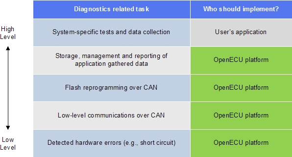
The OpenECU diagnostics infrastructure has been tailored to meet the following legislation. In many cases, the exact description for a particular behaviour has to be extracted from more than one document.
For European OBD documents, most of the emissions related legislation is held within Directive 70/220/EEC, which has been amended many times over the years. OBD requirements are held within Annex XI, which itself was created and subsequently modified by directives:
1998/69/EC
1999/102/EC
2002/80/EC
2003/76/EC
For heavy-duty diesel vehicles the Commission brought in Directive 2003/522. Subsequently, Directive 2005/55/EC introduced additional requirements for Euro-V emissions compliant diagnostic systems from 2008 or 2009 onwards. This was in turn amended by:
2005/78/EC
2006/51/EC
2008/74/EC
For Euro-VI heavy duty diesel vehicles, the previous regulations were revoked and a new Commission Directive 582/2011 was put in place.
The Californian (CARB) diagnostics requirements are captured within Title 13 California Code of Regulations in either section 1962.8 for passenger cars, light and medium duty vehicles or section 1971.1 for heavy duty vehicles.
Scan tool communications fall into two main categories: heavy duty using J1939 and light duty using ISO15765 based protocols. The second (light duty) category also includes the original J1979 diagnostic service requirements (also described in ISO15031-5) as well as the higher numbered KWP2000 and UDS services.
The J1939 requirements are based on the SAE standards:
J1939-03 On Board Diagnostics Implementation Guide
J1939-73 Application Layer - Diagnostics
J1939-21 Network Layer (Transport Protocol)
The ISO related requirements are based on:
ISO15031, parts 5,6 and 7
ISO15765, parts 2,3 and 4
The implementation within the OpenECU platform attempts to steer a course through these various diagnostics requirements. At times they conflict and in such cases, the implementation allows the user to select one alternative or another. There are also cases where a user may want to deliberately over-ride some aspect of the protocol or diagnostic requirements (e.g. during manufacturing). In these cases, the platform provides the user application with the ability to make those changes. Therefore it is essential that the application works together with the platform to provide a coherent and legally compliant diagnostic system. It cannot be left to just one side or the other.
One of the more confusing areas is the overlap between J1939-73 and ISO15031-5 (J1979) services for the generic, mandatory services. Both protocols have the ability to transmit more or less the same information, but in wildly different ways. The following table is loosly derived from one in J1939-73 and attempts to translate between the two.
Table 8.1. Diagnostic Service Comparisons
| ISO/J1979 Service | ISO Description | J1939 DM | J1939 Description |
|---|---|---|---|
| 0x01 PID 00 | Request Powertrain Data - index of supported PIDs | DM24 | Use DM24 to declare emissions related support for powertrain data and DM25 freeze frame |
| 0x01 PID 01 | Number of DTCs, MIL status, supported monitors and their status (readiness) | DM5 | OBD compliance, previously active and active DTC count monitors supported and their status (readiness) |
| 0x01 PIDs 03-1B | Actual current powertrain parameter data | Various | Normally provided PGs will be used to retrieve the parameter data |
| 0x01 PID 1C | OBD legislation supported | DM5 | Which OBD legislation is supported |
| 0x01 PID 21, 4D, 31, 4E | Distance and time while MIL on, Distance and time since DTCs cleared | DM21 | Diagnostic Readiness 2 reports this data |
| 0x01 PID 41, 1F, 30 | Continuously monitored systems status, time since engine start, number of warm ups since DTCs cleared | DM26 | Diagnostic Readiness 3 reports status of monitors on this data |
| 0x02 | Freeze frame data - byte00 says which PIDs supported, byte02 says which DTC caused each freeze frame, bytes 04-FF have the data | DM4, DM24/DM25 | DM 4 contains basic freeze frames - note the PG tells what DTC caused it and the PG contains standard parameter data. DM25 provides more parameter support than DM4. DM24 says which SPNs are supported. |
| 0x03 | Emission-related powertrain DTCs | DM1 or DM12, DM23 | Emissions related active(MIL on) DTCs and lamp status regular message on DM1 or when required on DM12. DM23 can report DTCs which are confirmed but the MIL is off. |
| 0x04 | Clear all emissions related OBD data | DM3 or DM11 | DM3 clears previously active DTCs and DM11 clears all DTCs |
| 0x05 | Oxygen sensor test data (use service 0x06 instead) | Not used | No planned support for specific oxygen sensor data |
| 0x06 | Test results for non-continuously monitored systems | DM10, DM7, DM8, DM30 | DM10 gives the test IDs supported, DM7 invokes the test and DM8 or DM30 are used to report the test results |
| 0x07 | Emissions-related Pending DTCs | DM6, DM27 | DM6 has emissions related Pending DTCs and DM27 has all Pending DTCs |
| 0x08 | Request control of onboard system, test or component | DM7, DM8 | DM7 commands the test and DM8 reports the results |
| 0x09 Infotype 00 | Infotype 00 declares which other infotypes are supported | Various | Individual DMs used for specific infotype data |
| 0x09 Infotype 01 / 02 | Vehicle's VIN number | Data Stream | Reported on Data Stream (J1939-71), using PGN 65260 |
| 0x09 Infotype 03 / 04 | Vehicle information - Calibration ID | DM19 | Bytes 5-20 contain calibration information |
| 0x09 Infotype 05 / 06 | Vehicle information - Calibration verification number (CVN) | DM19 | Bytes 1-4 contain CVN |
| 0x09 Infotype 07 / 08 | In use performance ratios for diagnostic monitors | DM20 | Indicates how often monitors complete compared to vehicle operation |
| 0x09 Infotype 09 / 0A | ECU acronym and name | ||
| 0x0A | Permanent DTCs (emissions related) | DM28 | Permanent DTCs (emissions related) |
The approach to implementing the diagnostics functions is a balance between providing flexibility and requiring minimal intervention. The user needs the ability to configure their data and choose which services to support. In some cases, the scan tool interactions do not require additional user code (model) as the data is well structured and can be reported simply by the OpenECU platform.
The Simulink blockset provided does not force any particular structure or hierarchy onto the user. The OpenECU build system will gather data about DTCs, freeze-frames, PIDs, monitors etc at build time and generate an appropriate set of embedded data structures for that particular system. This allows the user to implement diagnostic functions throughout their model without carrying any extra overheads within the embedded code.
The diagnostics system works closely with the NVM file system. Again, the user has some flexibility in terms of allocating certain amounts of memory or choosing when data is written, but for the most part, this interface is seamless and diagnostic data is stored and retrieved safely with minimal input from the user. The freeze-frames potentially take the largest amount of NVM, which is controlled via the pff_Configuration block.
Communications with the scan tool behave slightly differently for J1939 compared to ISO15765 and related protocols. For J1939, the user’s application model is required to provide data for the reply to a scan tool request. However, for most of the ISO15765 standard services, the data is retrieved by the platform and sent back to the scan tool with minimal intervention from the user’s application model.
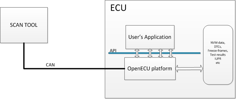
Diagnostic Trouble Codes (a.k.a. DTCs or fault codes) are the basic building blocks of the diagnostic infrastructure. There are multiple standards for the fault information to follow as well as choices for its life-cycle depending on whether it is emissions-related or permanent and the legislation being followed. These details are selected within the Simulink definition block for each DTC and allow the user to configure the system for various aspects of diagnostic legislation.
DTCs may be grouped into tables to help the user manipulate them. They can then be cleared (by table name) if required.
DTCs will also have an associated freeze-frame that is stored when the fault occurs. The user may specify several different types of freeze-frame for use with different DTCs. The various freeze-frame definitions may include more or less data to be captured when a fault occurs. Note that the legislation requires some specific pieces of data to be captured for emissions related faults.
For a specific piece of data to be captured in a freeze-frame, the application needs to point it out to the platform. This is one of the uses of the PID block (J1939 SPN data). The platform can grab the latest data from the inport to the PID block when required. The same PID block mechanism allows the OpenECU platform to provide real-time data from within the user’s model to a scan tool (e.g. for J1979 service $01 or J1939 DM24).
The user may implement the DTC, PID and freeze-frame blocks anywhere in the model. At build time, the OpenECU system will search the user’s model to find all potential DTCs and associated freeze-frame definitions and will allocate sufficient memory depending on the number and type of DTCs and freeze-frames.
The build process will automatically create a constant
named pff_dtc_sev_overrides_ff_age with a default value
of "FALSE". This is used to determine if the severity of the DTC takes precedence
over age when faced with lack of space to store freeze-frames in NVM.
Selection of the desired behaviour is configurable at the C-API level (via option ff-store-by-dtc-severity), but
this has not yet been implemented in Simulink; Simulink models will currently always select age of DTC to take
precedence in storage.
Here's an example of J1939 SPN data being collected via two PID blocks. This data can now be used in freeze frames as well as reported via DM24. The PID blocks can be placed anywhere in a model to gather data from the most convenient places. To incorporate this data into a freeze frame, use a vector calibration containing the list of PID identifiers(J1979) or SPNs(J1939) in the pff_FreezeFrame block.
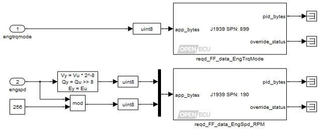
There are user configurations related to freeze-frames, which determine the total number to capture and the maximum amount of RAM and NV memory to allocate for freeze-frames. This allows the user to limit the allocation of memory (e.g. in the event of repeated faults) while at the same time making maximum use of the resources available in the ECU. This flexibility means that the system can be tailored to be more useful during development phases (when extra memory may be available) and then scaled back for the production version without changes to the model structure.
The Simulink block pdtc_DiagnosticTroubleCodeExt is the main dialog for each fault in describing how it should behave. In particular, note the distinctions between CARB permanent and Euro non-eraseable DTCs. In each case the conditions required to clear the DTC are fully specified in the relevant legislation.
A complete emissions related diagnostic system will have a have a set of diagnostic monitors to check the performance of each of the various components on a vehicle. These diagnostic monitors are in turn made of a series of diagnostic tests. The individual tests may be performed continuously, for example checking the range of an analogue input or the state of an output signal. Alternatively the tests may be classed as non-continuous which means that they can only be performed when the vehicle is in a certain operating state, for example checking the performance of a catalyst or the EGR sub-system.
The OpenECU platform allows the user to define the monitors and related tests in the system using the ppr_DiagnosticMonitorEntity and ppr_DiagnosticTestEntity blocks.
The user's application must use these blocks in conjunction with their individual diagnosis algorithms and provide data from each time an individual test is performed. The data is used in two ways by the platform:
Firstly, each time a test is run, this allows the platform to update the numerator and denominator to be used in calculating the In-Use-Performance-Ratio for that particular diagnostic.
Secondly the most recent test results (and limits) must be available for communication to a scan tool. The platform will store this data in NVM (to keep it in the event of a power down) for future communication to a scan tool.
Note
The legislation has some specific values (MonitorID) that must be used for specific sub-system emissions monitors.
In this example, we will build a hypothetical flow monitor which is to be part of an emissions compliant system and therefore needs to meet legal diagnostic requirements. We shall build it to meet Californian OBD regulations and the scan tool will use ISO 15765 to communicate with the ECU.
The flow monitor is made up of two individual flow tests, each of which can only be performed under certain conditions. The application needs to select the conditions to trigger each of the actual tests. In legal terms, this is a non-continuous monitor and therefore needs to inform the system when it can run for use in determining the In Use Performance Ratio (numerator / denominator).
The Simulink model below shows a set of conditions for each of the tests being used to enable two further sub-systems. Each of those sub-systems will contain an individual flow test and associated interfaces.
At the monitor level, the application uses the ppr_DiagnosticMonitorEntity block. There are inputs for when the tests are running, when they have completed and there is also the ability to force data into the block. These forcing inputs have been grounded (set to FALSE). The output of the DME block provides the latest value of the numerator/denominators associated with the overall flow monitor.
Also shown are the two ppr_DiagnosticTestEntity blocks for the two individual tests. These receive the data for individual test results, limits and individual numerator/denominator updating.
For an ISO based scan tool, the data is accessed by a Service $06 command. Passing the data to the scan tool is handled directly by the platform, so in this case, the DME and DTE block outputs are for information only.
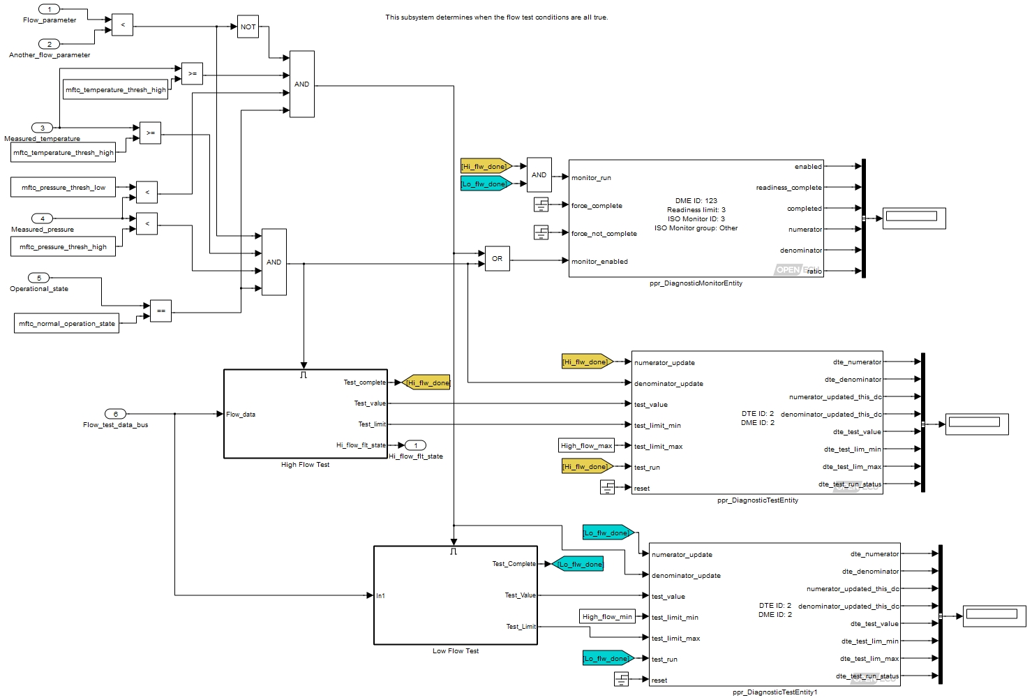
We’ve invented two individual tests which make up our flow monitor. The principle is the same for each, so will only consider one here.
The Simulink model below shows how an individual pass/fail result is used to set and clear DTCs.
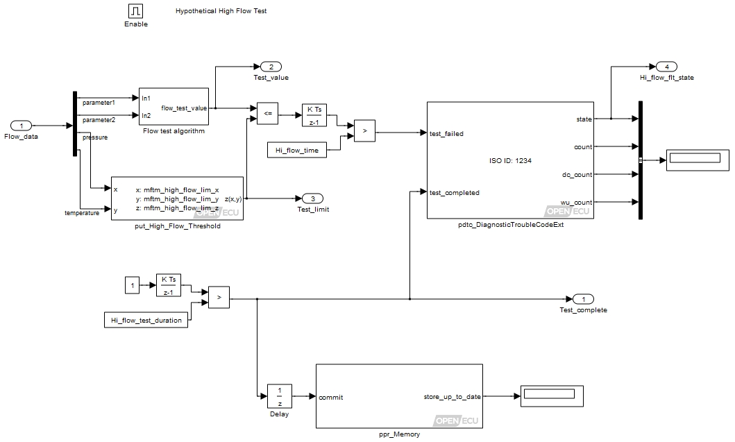
We’ve made up some imaginary table which provides a test limit. The flow test algorithm computes a value which is compared against this limit. If the value is greater than the limit, then an integrator adds up the time for which it is over the limit. Once suitable time has passed, the test is considered to have failed and a fault code will be stored by triggering the DTC block. These DTC blocks may exist anywhere within the Simulink model.
The duration integrator allows for sufficient time to pass and if the test value was not above the limit, the test will be completed and passed.
Note that the test limits and test value are passed out to the DTE block for use in the event of a scan tool service $06 request. The platform is asked to store the new results after a short delay. This is required, as the service $06 request needs to be given the most recent test results, even if those results are days or even weeks old.
When a DTC is triggered (via the test_failed inport as shown above) an emissions related system must capture a freeze frame. This mechanism uses the PID and freeze-frame blocks ppid_Pid and pff_FreezeFrame.
Some examples of hooking up other diagnostics related blocks into the application model are shown below. Note that these examples will only exist in one place within the Simulink model.
Firstly, an example of how the lamp outputs can be used. Here, we have configured the MIL lamp as a CAN output, the Red Stop Light and Amber Warning Light as digital outputs on this module and the Protection Lamp is not used.
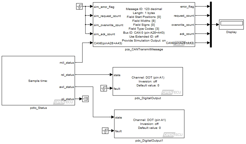
The next model snippet shows the setting of some of the generic counters. Note that this has some slightly simplified logic.
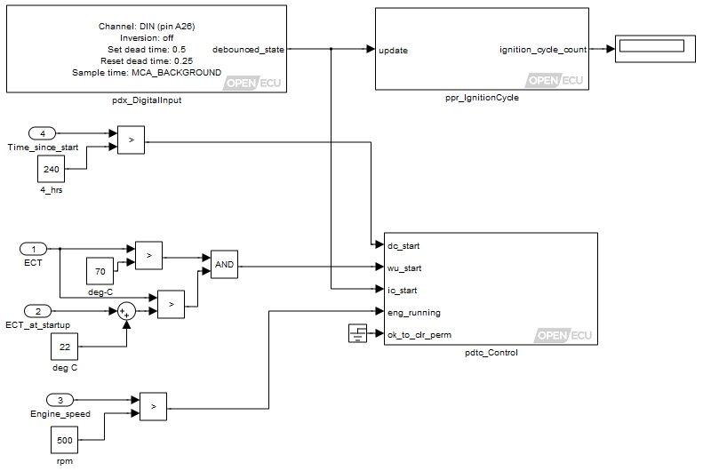
There are additional blocks to force NVM storage – this can be done by the user on a periodic basis or perhaps only after tests have completed and new results are available or when DTCs have been set. The blocks are shown in the example models.
Once a model has been built with the diagnostics integrated, there is very little left for the application to do to respond correctly to J1939/ISO 15031 scan tool requests. The platform keeps track of any DTCs and whether they are classed as “pending” or “active” etc. The data entered into each DTC block will define this. As drive-cycles and warm-up cycles go by, fault data and freeze-frame data will be erased if they don’t recur. Similarly as individual tests happen, the test result data is stored, together with the numerator/denominator counts for each of the defined monitors.
If a scan tool now follows the J1979/ISO 15031 standard to request emissions data, the OpenECU system will respond with the correctly formatted data for each request. The full list of emissions related diagnostic services are detailed below.
The build process will automatically create a calibration
variable named pdgc_emissions_report_min_sev with a default value
of "sev-c". This calibration is used to determine the emissions severity level at or
above which the platform will include a DTC when responding service requests.
The build process will create entries for this value in the A2L file for sev-a (highest), sev-b1, sev-b2, sev-c, or sev-none (lowest). To emit all DTCs regardless of their emissions severity level, use sev-none.
Table 8.2. PDG supported services
| ID | Service | Notes |
|---|---|---|
| 0x01 | Request Current Powertrain Diagnostic Data (J1979) | Used to read PID values that have a J1979 8-bit identifier defined |
| 0x02 | Request Powertrain Freeze Frame Data (J1979) | Used to read PID values that have been captured when a DTC occurred |
| 0x03 | ReadEmissionDTCs (J1979) | Reports only DTCs defined as emission-related |
| 0x04 | ClearEmissionDTCs (J1979) | Clears only DTCs defined as emission-related |
| 0x06 | RequestOBDTestResults (J1979) | Reports test results for ISO test IDs |
| 0x07 | ReadEmissionDTCsPending (J1979) | Reports only DTCs defined as emission-related that are pending |
| 0x09 | RequestVehicleInformation (J1979) | Used to read Vehicle Information data stored as InfoTypes |
| 0x0A | ReadEmissionDTCsPermanent (J1979) | Reports only DTCs defined as emission-related that are permanent |
| 0x10 | StartDiagnosticSession (KW2000-3) or DiagnosticSessionControl (UDS) | Used to request a change between diagnostic sessions. (Default, Extended and Programming) |
| 0x11 | ECUReset (KW2000-3, UDS) | Used to reset the ECU. Only supported by Bootloader to exit reprogramming mode |
| 0x14 | ClearDiagInfo (KW2000-3, UDS) | Clears all or subgroup of ISO DTCs (not J1939-only DTCs) |
| 0x17 | ReadStatusOfDTC (KW2000-3) | Reports the status of the specified DTC |
| 0x18 | ReadDTCByStatus (KW2000-3) | All DTCs, regardless of emissions severity |
| 0x19 | ReadDTCInfo (UDS) | 16-bit DTCs currently output, lower byte zero; many subfunctions |
| 0x21 | ReadDataByLocalIdentifier (KW2000-3) | Used to read PID values using an 8-bit identifier |
| 0x22 | ReadDataByCommonID (KW2000-3, UDS) | Used to read PID values using an 16-bit identifier |
| 0x23 | ReadMemoryByAddress (KW2000-3, UDS) | Used to read raw memory contents (subject to security restrictions) |
| 0x24 | ReadScalingDataByIdentifier (UDS) | Used to read scaling data for a PID |
| 0x27 | SecurityAccess (KW2000-3, UDS) | Used to grant security access in boot loader mode |
| 0x28 | CommunicationControl (UDS) | Used to switch on/off the transmission and or the reception of certain messages |
| 0x28 | DisableNormalMessageTransmission (J2190) | Used to switch off the transmission of non-diagnostic and non-network management messages |
| 0x29 | EnableNormalMessageTransmission (J2190) | Used to switch on the transmission for all messages |
| 0x2A | ReadDataByPeriodicIdentifier (UDS) | Used to request automatic periodic transmission of selected PIDs |
| 0x2C | DynamicallyDefineDataIdentifier (UDS) | Used to specify a new PID composed of other PIDs or memory reads |
| 0x2E | WriteDataByLocalIdentifier (KW2000-3, UDS) | Used to write PIDs specified by 16-bit identifier (eg NV PID data) |
| 0x2F | IOControlByCommonID (KW2000-3, UDS) | Used to override PID values using a 16-bit identifier |
| 0x30 | IOControlByLocalID (KW2000-3, UDS) | Used to override PID values (identified by KW2000 8-bit local identifier) |
| 0x31 | RoutineControl (UDS) | Used to initiate a specified process in boot loader mode, e.g. erase memory |
| 0x34 | RequestDownload (KW2000-3, UDS) | Used to initiate a downloading of a block of memory in boot loader mode (only the downloading of unencrypted, uncompressed data is currently supported) |
| 0x36 | TransferData (KW2000-3, UDS) | Used to download data in boot loader mode (only the downloading to flash is currently supported) |
| 0x37 | RequestTransferExit (KW2000-3, UDS) | Used to terminate data transfer between the tester and the ECU in boot loader mode |
| 0x3E | TesterPresent | “Ping” to maintain communications |
| 0x85 | ControlDTCSetting | Used to Stop or Start the setting of DTCs |
Note
Services $14, $17 and $18 use the ISO 15031-6 values for groupOfDTC groups in KW2000-3 style (powertrain 0x0000, chassis 0x4000, body 0x8000, network/other 0xC000, all 0xFF00). For $14, the equivalent 24-bit UDS values may alternatively be used (0x000000, 0x400000, ... and 0xFFFFFF for 'all').
Note
Please contact Pi Innovo for support with flash reprogramming. The EraseMemory routine ($FF00) typically specified by OEMs is supported in two formats:
Numeric range: If a length is supplied, the address value is interpreted as an actual device address and the specified range is erased.
Logical index: If no length is supplied, the address value is interpreted as the zero-based index of the eraseable flash block, which is device-dependent. For example, the MPC5534 M0 block (0x40000 - 0x5FFFF) has index 6. This follows the HIS group reprogramming specification.
The OpenECU interface for J1939 responses is somewhat different. In this case, the application has to determine the nature of the request and initiate a response. This is assisted by the provision of the J1939 request/response blocks. The application needs to detect a particular request and then trigger the appropriate diagnostic action (most likely via another platform block). The platform makes the data available to the application, which it must then feed into the appropriate J1939 response block.
Generic J1939 receive and transmit blocks are provided, but are only useful where the reply is a fixed length. When the reply may be of a variable length, the special response blocks should be used. They will invoke the J1939 transport protocol for multi-frame replies (if necessary). See here Section 4.6.3.3, “J1939 (SAE) communications” for the full list of J1939 blocks provided by OpenECU.
An example of the J1939 request/response layout is shown in the model below.
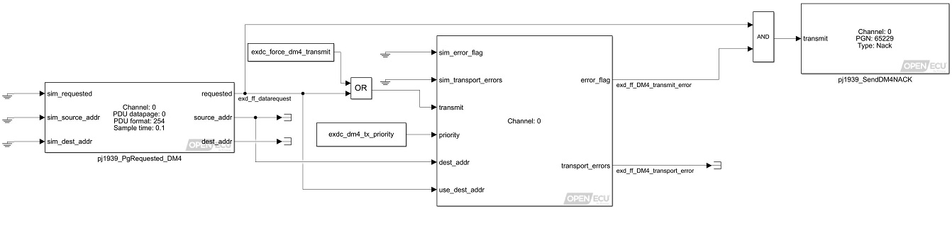
This example is for DM4. The same request/response arrangement should be used for all J1939 DM requests. OpenECU provides a specific transmit block for each DM that has a variable length response.
Calculates the calibration verification number of the code and calibration memory regions.
EXT_DIAG (Extended diagnostics library). (See Section 1.3, “Licensed Features”.)
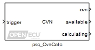
The CVN is calculated using CRC-16-CCITT. The reported CVN is composed of the code area CRC and calibration area CRC. The calibration area CRC occupies the 2 most significant bytes. The code area CRC occupies the 2 least significant bytes. Memory regions which are expected to change during normal ECU operation have been omitted from both code and calibration CRCs. The code area CRC excludes the file storage area. DTCs, freeze frames, etc, are stored in the file storage memory region. The calibration area CRC excludes adaptive calibrations. Unused memory areas have been omitted from both code and calibration CRCs.
Note that when the calibrations are mapped to RAM on development ECUs (i.e. whenever one can actually calibrate on-the-fly), changing those calibrations will affect the CVN. This is not the case for production units when the calibration is fixed and stored in non-volatile memory (NVM). When runtime calibration changes are made via CCP, the currently calculated CVN will be invalidated, and the available outport will be set to FALSE until the CVN is recalculated with a rising edge on the trigger inport.
The calibration verification number (CVN) is computed in the background task. Multiple invocations of the background task are used to calculate the CRC so as to prevent a watchdog timeout. At each invocation the CRC is calculated for a relatively small chunk of memory.
Background checking for code or calibration corruption works through the Calibration Verification Number computation on supported targets with the OBD library option. Ensure that the CVN is recomputed continually if run-time corruption checking is required. If it is detected, an unrecoverable error is raised (resulting in ECU reset). This is in addition to boot-time checksum validation.
After the CVN has been calculated for the first time, it will be automatically stored in NVM and recalled by the block during initialization on the next reset. The available and cvn outports will be updated with the previously calculated results after a power cycle.
The calculated CVN is supplied to the application from this port. The supplied CVN is composed of the code area CRC and calibration area CRC. The calibration area CRC occupies the 2 most significant bytes. The code area CRC occupies the 2 least significant bytes.
Value type: Integer This port indicates the availability of the CVN.
FALSE - CVN not available.
TRUE - CVN available.
Once a CVN has been calculated returns TRUE until ECU reset, i.e. triggering further CVN calculations does not alter this value.
Value type: Boolean True if the CVN is currently being calculated, otherwise false.
Value type: Boolean
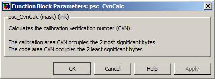
Set all DTCs referred to by the table identifier parameter, to the clear state, if the clear state is supported by the DTC.
See Section 6.1.35, “DTC clear all (pdtc_ClearAll)” for a detailed description.
Set all DTCs referred to by the table identifier parameter, to the clear state, if the clear state is supported by the DTC, and if the DTC state is currently active.
See Section 6.1.36, “DTC clear all if active (pdtc_ClearAllIfActive)” for a detailed description.
Set all DTCs referred to by the table identifier parameter, to the clear state, if the clear state is supported by the DTC, and if the DTC state is currently "inactive" or "previously active".
See Section 6.1.37, “DTC clear all if inactive (pdtc_ClearAllIfInactive)” for a detailed description.
Clear all DTCs which match the DTC type, DTC emissions severity and DTC state, in accordance with the comparator parameters.
EXT_DIAG (Extended diagnostics library). (See Section 1.3, “Licensed Features”.)
Given a DTC table, clear all DTCs (if the clear state is supported by the DTC), which match the block parameters DTC type (in accordance with comparator Type comparison), DTC emissions severity (in accordance with comparator Emissions severity comparison), DTC state (in accordance with comparator State comparison). This block provides for configurable clearing of DTCs according to the user requirements e.g. the user may wish to clear all DTCs in a given table that are of type ISO only, with emissions severity greater than B1 and with state not equal to active.
The user may also select to clear DTCs only according to OBD regulations (e.g. following CARB regulations for permanent DTCs or Euro non-erasable DTCs), or may select to clear DTCs unconditionally.
Set to 1 to force the state of each DTC to state clear which match the block parameters DTC type (in accordance with comparator Type comparison), DTC emissions severity (in accordance with comparator Emissions severity comparison), DTC state (in accordance with comparator State comparison).
Value type: Boolean Calibratable: No
The name of the DTC table to act on (there must be a corresponding named table specified in a pdtc_Table block in the model).
Value type: String Calibratable: No A drop-down selection of the comparison to perform on the DTC's type (first step) when clearing DTCs, in the DTC table (specified by parameter DTC table identifier). See parameter DTC type for the second step.
Value type: List Calibratable: No A drop-down selection of the type of DTCs to use (second step) for clearing DTCs in the DTC table (specified by parameter DTC table identifier). If the parameter Type comparison is set to 'Any' then this drop-down is not available.
Value type: List Calibratable: No A drop-down selection of the comparison to perform on the DTC's emissions severity (first step) when clearing DTCs, in the DTC table (specified by parameter DTC table identifier). See parameter DTC emissions severity for the second step.
Value type: List Calibratable: No A drop-down selection of the emissions severity to use (second step) for clearing DTCs in the DTC table (specified by parameter DTC table identifier). If the parameter Emissions severity comparison is set to 'Any' then this drop-down is not available.
Value type: List Calibratable: No A drop-down selection of the comparison to perform on the DTC's state (first step) when clearing DTCs, in the DTC table (specified by parameter DTC table identifier). See parameter DTC state for the second step.
Value type: List Calibratable: No A drop-down selection of the DTC state to use (second step) for clearing DTCs in the DTC table (specified by parameter DTC table identifier). If the parameter State comparison is set to 'Any' then this drop-down is not available.
Value type: List Calibratable: No If checked, this block will clear DTCs matching the comparison criteria above unconditionally, regardless of whether they are configured as CARB permanent DTCs or as Euro non-erasable DTCs.
If unchecked, this block will only clear DTCs which match the comparison criteria above, and which are permitted to be cleared at this time by OBD regulations. Any CARB permanent DTCs will be cleared under the conditions of the CARB regulations, and Euro non-erasable DTCs will never be cleared.
Typically this would be unchecked for clearing DTCs via OBD scan tool request, and would be checked for a full reset of DTCs during production or in other situations where OBD regulations on clearing DTCs are not relevant (e.g. moving the ECU to a different vehicle).
Value type: Boolean Calibratable: No
Start new drive, warm-up and ignition cycles. Handle engine running signal. Handle vehicle/operating conditions for OBD clear of CARB permanent DTCs.
EXT_DIAG (Extended diagnostics library). (See Section 1.3, “Licensed Features”.)
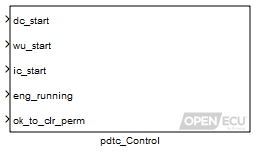
Platform control of DTCs can depend on the number of drive, warm-up and ignition cycles that have taken place as well as the engine running state. This block is used to signal the start of each cycle and the engine running state. It is up to the application to determine the conditions for starting each of the cycles and the engine running state, as these can be dependent on the regulatory requirements that are being adhered to.
When an OBD clear request is received, any relevant CARB permanent DTCs will not be cleared immediately. Instead they will be cleared at the end of this drive cycle (or a subsequent drive cycle) if the relevant test has been carried out and passed (and has not subsequently failed again). In addition, DTCs relating to certain monitors are required to wait for certain vehicle/operating conditions to be met during a drive cycle before permanent DTCs for these monitors may be cleared, where these vehicle/operating conditions will have exercised a representative range of vehicle behaviour and any existing fault is likely to have been detected. It is up to the application to determine whether these conditions have been satisfied, as these can be dependent on the regulatory requirements that are being adhered to.
A transition from 0 to 1 indicates the start of a new drive cycle. The input should remain high throughout the drive cycle, but it must be switched low for at least one iteration between cycles.
Value type: Boolean Calibratable: No A transition from 0 to 1 indicates the start of a new warm-up cycle. The input should remain high throughout the warm-up cycle, but it must be switched low for at least one iteration between cycles.
Value type: Boolean Calibratable: No A transition from 0 to 1 indicates the start of a new ignition cycle. The input should remain high throughout the ignition cycle, but it must be switched low for at least one iteration between cycles.
Value type: Boolean Calibratable: No Set to 1 for engine running. Set to 0 otherwise.
Value type: Boolean Calibratable: No Set to 1 to indicate that vehicle/operating conditions are currently met such that an OBD clear request may be carried out for permanent DTCs. Set to 0 otherwise.
Value type: Boolean Calibratable: No
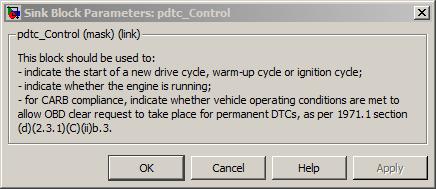
Define a diagnostic trouble code, and provide the platform with information relating to its fault conditions.
EXT_DIAG (Extended diagnostics library). (See Section 1.3, “Licensed Features”.)
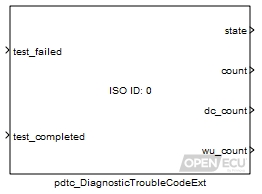
A diagnostic trouble code (DTC) is a unique indicator used to remember the state of a fault. This block supports platform-controlled fault handling for emissions-related and non-emissions-related faults. The model determines if the conditions for progressing the platform's fault handling state machine are satisfied or not, and passes this information to the pdtc_DiagnosticTroubleCodeExt block. The state of any fault can be maintained by the block while the model is running, and also across power cycles (see the pdtc_Memory block for more details).
There are two types of DTC currently supported - J1939 and ISO-15765 - although more may be added in the future. Each DTC can be defined as either a single type, or a combination of both J1939 and ISO types.
Each DTC can be in one of four states. Its state is Clear if its fault conditions have never been present, or if a previously active fault has healed itself (its fault conditions have not been present for a sufficient amount of time). Its state is Pending if its fault conditions are present, but have not been present for long enough to confirm the fault. Its state becomes Active if a Pending DTC's fault conditions persist long enough for it to be confirmed, or if a Previously Active DTC's fault conditions return. Its state becomes Previously Active if an Active DTC's fault conditions have been not been present for a sufficient amount of time.
The library will transition through the different states, Clear, Pending, Active and Previously Active based upon the inputs from the application, test_failed and test_completed as well as information regarding current drive cycle and warm up cycle count.
State transitions are also affected by the action selected when a DTC reaches Previously Active but the test then fails again. Behaviour in this situation is not specified by CARB (and therefore not by other OBD specifications deriving from CARB), so behaviour is manufacturer-specific. One possible interpretation is that the DTC should simply return immediately to Active. The other possible interpretation is that the DTC should return to Pending: in this case, if the test continues to fail then the DTC transitions to Active; or if the test passes for the duration of another drive cycle then the DTC returns back to Previously Active (instead of returning to Clear as a DTC would usually do from Pending state). Selection of the desired behaviour is configurable at the C-API level, but this has not yet been implemented in Simulink; Simulink models will currently always select the latter interpretation (transition to Pending) for DTC.
If transitions between Previously Active and Pending states are disabled, the following diagram describes the DTC state transitions.
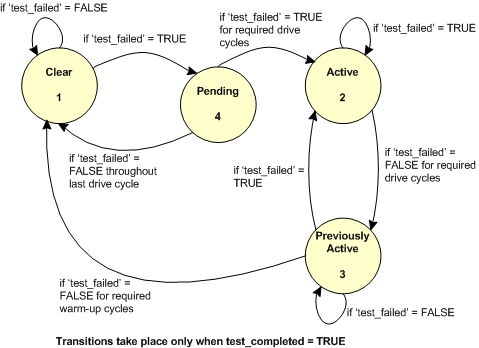
If transitions between Previously Active and Pending states are enabled, the following diagram describes the DTC state transitions.
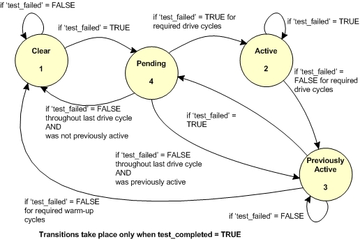
The library keeps track of drive cycles and warm-up cycles based on calls by the application to the pdtc_Control block.
Detection of warm-up and DTC ageing in the Previously Active state is not as straightforward as it might at first appear. OBD regulations (in particular CARB and European regulations) define "drive cycles" unambiguously, but are less clear on the definition of a "warm-up cycle". It has therefore been necessary to adopt an interpretation which is believed to be the most stringent possible interpretation, so that regulatory compliance can be assured. Regulations
The OpenECU interpretation of a warm-up cycle is "an ignition cycle in which a warm-up (as reported by the customer) occurs". The test causing a DTC to be raised must also run and pass during the same ignition cycle in which the warm-up occurs, in order for the DTC to be aged by one warm-up count. The following diagram describes scenarios which illustrate how this will work in an application.
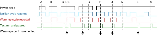
At points A and B a test has not been run and passed in the same warm-up cycle, so the warm-up count is not incremented.
At point C the warm-up has not yet occurred when the test is run and passed, so the warm-up count is not incremented. At point D the warm-up occurs, and as a result of the test having been previously run and passed, the warm-up count is incremented. Further instances of the test running and passing during this ignition cycle (E) do not affect the warm-up count, because this is required to count warm-ups and not test executions.
At point F the test is run and passed when the warm-up has already occurred, so the warm-up count is incremented immediately. Further instances of the test running and passing during this ignition cycle (G) again do not affect the warm-up count.
Due to power-hold relays, capacitors or other system behaviour, the ECU may not lose power when the ignition is cycled. Points H and J illustrate that tests carried out on subsequent ignition cycles with warm-ups will increment the warm-up count, even if the ECU has not been powered off. Point K illustrates that the requirement for test run and warm-up remains.
Tests may also be required to take place during the power-hold period. Point L illustrates that the warm-up count will be incremented during the power-hold period if a warm-up cycle has previously taken place this ignition cycle. Point M illustrates that the requirement for warm-up still exists during the power-hold period.
Note that this diagram does not mention drive cycles, as these are calculated independently and do not affect warm-up (except insofar as they are based on conditions arising in the same vehicle). Note also that the diagram does not mention warm-ups reported with the ignition off, because the regulatory definition of a warm-up requires the engine to be on (and hence the ignition to be on).
Changes to DTC states are written to non-volatile storage when block Section 6.1.40, “DTC memory update (pdtc_Memory)” is invoked with a request for commit to storage. This will typically occur on shutdown and at periodic intervals during execution. If DTCs have not changed since the last write to non-volatile storage, invocation of the block Section 6.1.40, “DTC memory update (pdtc_Memory)” has no effect, maximising the lifespan of non-volatile storage.
If the DTC cannot be recalled from non-volatile memory (which includes the first time the ECU is powered up), then the library initialises the DTC as follows:
Table 8.3. DTC initialisation values
| DTC information | Initial value |
|---|---|
| State | Clear |
| Number of Times Set Active Count | 0 |
| Drive Cycle Count | 0 |
| Warm-up Cycle Count | 0 |
| Test Run This Drive Cycle | No |
| Test Not Complete | Yes |
Set to the value of the current DTC state (see the DTC states descriptions for a list of states and values).
Value type: Integer Calibratable: No A count of the number of times a J1939 DTC has changed to the active state. Available only if the parameter DTC type is J1939 DTC, and currently not supported by the platform-controlled fault handling.
Range: [0, 127] counts - 0 to 126 (The value 127 is reserved for indicating not available).
Value type: Integer Calibratable: No Drive cycle count. The number of drive cycles to 'debounce' the DTC state before setting it to active. This is exported for information only, as the platform is responsible for progressing the state machine.
Range: [0, 127]
Value type: Integer Calibratable: No Warm-up cycle count. The number of warm-up cycles in which the DTC has not failed - used to 'heal' faults that are no longer present. This is exported for information only, as the platform is responsible for progressing the state machine.
Range: [0, 127]
Value type: Integer Calibratable: No
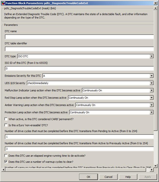
An optional name can be given to a DTC to identify it for calibrating the ID parameters. If no name is given, it will be allocated a name when the model is built. Note that this allocated name can change between builds, so should not be use for calibration. If a DTC will need to be calibrated, it should be explicitly named.
Generation of DDE entries for DTCs needs to be enabled. See Configuration options for more details.
Value type: String Calibratable: No The name of the DTC table to store this DTC in (there must be a corresponding named table specified in a pdtc_Table block in the model).
Value type: String Calibratable: No A drop-down selection of the type of the DTC.
Value type: List Calibratable: Yes, offline The value of the SPN for this DTC. The parameters Suspect parameter number, Failure mode indicator and Conversion method uniquely identify the DTC. Available only if the parameter DTC type includes J1939 DTC.
Range: [0, 524287]
Value type: Integer Calibratable: No The value of the FMI for this DTC. The parameters Suspect parameter number, Failure mode indicator and Conversion method uniquely identify the DTC. Available only if the parameter DTC type includes J1939 DTC.
Range: [0, 31]
Value type: Integer Calibratable: Yes, offline The value of the CM for this DTC. The parameters Suspect parameter number, Failure mode indicator and Conversion method uniquely identify the DTC. Available only if the parameter DTC type includes J1939 DTC.
Range: 0 or 1
Value type: Integer Calibratable: Yes, offline The value of the ID for this DTC. This ID uniquely identifies the DTC. Available only if the parameter DTC type includes ISO DTC.
Range: [0, 65535]
Value type: Integer Calibratable: Yes, offline A drop-down selection of the emissions severity level at which a DTC fits. This allows the modeller to combine "emissions related" and other DTCs within the same system.
Value type: List Calibratable: Yes, offline A drop-down selection of the UDS service $19 severity level for the DTC. Available only if the parameter DTC type includes ISO DTC.
Value type: List Calibratable: Yes, offline The action for the Malfunction Indicator Lamp when this DTC is active.
Range: [0, 3] (0 is Slow Flash, 1 is Fast Flash, 2 is On, 3 is Off)
Value type: Integer Calibratable: Yes, offline The action for the Red Stop Lamp when this DTC is active.
Range: [0, 3] (0 is Slow Flash, 1 is Fast Flash, 2 is On, 3 is Off)
Value type: Integer Calibratable: Yes, offline The action for the Amber Warning Lamp when this DTC is active.
Range: [0, 3] (0 is Slow Flash, 1 is Fast Flash, 2 is On, 3 is Off)
Value type: Integer Calibratable: Yes, offline The action for the Protection Lamp when this DTC is active.
Range: [0, 3] (0 is Slow Flash, 1 is Fast Flash, 2 is On, 3 is Off)
Value type: Integer Calibratable: Yes, offline Whether or not this DTC is considered 'permanent' (as defined by CARB/EPA) when the DTC is active. If the ECU is intended to comply with CARB, this should be selected for all DTCs that light the MIL.
Value type: Boolean Calibratable: Yes, offline Requires vehicle/operating conditions for OBD clear request
Available only if the parameter Permanent is true. CARB requires that for permanent DTCs, an OBD clear request does not immediately clear the DTC; instead the DTC may only be cleared when the ECU has verified that the fault is no longer present.
If this option is selected, vehicle/operating conditions as specified by CARB must have been met during a drive cycle since an OBD clear request was received, ensuring that the vehicle has been exercised over a range of behaviour which would be likely to detect any fault that still exists. The test for this DTC must then have been completed (during the same drive cycle or a later one) and report no fault existing. At the end of the drive cycle in which the test for this DTC is run, the DTC is cleared as per a normal OBD clear request.
If this option is unselected, vehicle/operating conditions are not required. The test for this DTC must have been completed and report no fault existing since the OBD clear request was received. At the end of the drive cycle in which the test for this DTC is run, the DTC is cleared as per a normal OBD clear request.
Vehicle/operating conditions met is indicated by the inport ok_to_clr_perm to the block pdtc_Control.
CARB requires that this option is selected for DTCs relating to specific monitors, and optionally may be selected for DTCs relating to other monitors.
Value type: Boolean Calibratable: Yes, offline Whether or not this DTC is non-erasable (as defined by Euro regulations).
Value type: Boolean Calibratable: Yes, offline The number of drive cycles for which the fault condition must be present before this DTC automatically transitions from Pending to Active. By default, this parameter is set to 1 (as recommended by the CARB regulations).
Range: [0, 255]
Value type: Integer Calibratable: Yes, offline Previously active drive cycles
The number of drive cycles for which the fault condition must be absent before this DTC automatically transitions from Active to Previously Active. By default, this parameter is set to 3 (as recommended by the CARB regulations).
Range: [0, 255]
Value type: Integer Calibratable: Yes, offline DTC de-activate using engine running time
Whether or not this DTC uses elapsed engine running time for it to transition from Active to Previously Active.
Value type: Boolean Calibratable: Yes, offline Elapsed engine running time for de-activation
The value of the elapsed engine running time for the DTC to transition from Active to Previously Active Available only if the parameter DTC de-activate using engine running time is checked.
Range: [0, 47185920] seconds
Value type: Integer Calibratable: Yes, offline Whether or not this DTC uses warmup cycles for it to transition from Previously Active to Clear.
Value type: Boolean Calibratable: Yes, offline The number of warm-up cycles for which the fault condition must be absent before this DTC automatically transitions from Previously Active to Clear. By default, this parameter is set to 40 (as recommended by the CARB regulations). Available only if the parameter DTC clear using warmup cycles is checked.
Range: [0, 255]
Value type: Integer Calibratable: Yes, offline DTC clear using engine running time
Whether or not this DTC uses elapsed engine running time for it to transition from Previously Active to Clear.
Value type: Boolean Calibratable: Yes, offline Elapsed engine running time for clear
The value of the elapsed engine running time for the DTC to transition from Previously Active to Clear. Available only if the parameter DTC clear using engine running time is checked.
Range: [0, 47185920] seconds
Value type: Integer Calibratable: Yes, offline Regulated exhaust level exceedance DTC
Whether or not regulated exhaust level exceedance applies to this DTC.
Value type: Boolean Calibratable: Yes, offline Whether or not this DTC has torque derate.
Value type: Boolean Calibratable: Yes, offline The amount of time until the derate will occur, should this DTC become active. Available only if the parameter Has torque derate is checked.
Range: [0, 225000] seconds
Value type: Integer Calibratable: Yes, offline Freeze frame associated with this DTC
A reference to the name of the frame frame to capture is entered here (see pff_FreezeFrame for specifics).
Value type: String Calibratable: No
Firstly, this indicates the required states of the Malfunction Indicator Lamp, the Red Stop Lamp, the Amber Warning Lamp and the Protection Lamp. These states are determined having taken into consideration the states of all DTCs in the system.
Optionally, values are output required to support EuroVI MIL activation and to populate messages with MIL and B1-severity fault time counter values.
EXT_DIAG (Extended diagnostics library). (See Section 1.3, “Licensed Features”.)
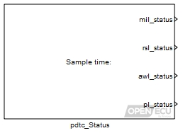
Each DTC in the system can specify which (if any) warning lamps are to be lit or flashed when they become active. This block reports the required states of these lamps. The relative priorities of the lamp states are (from highest to lowest) continuously on, fast flash, slow flash, and off. The highest priority lamp state of all of the active DTCs is indicated by this block.
Indicates the state of the Malfunction Indicator Lamp, taking into consideration the states of all DTCs in the system.
Range: [0, 3] (0 is Slow Flash, 1 is Fast Flash, 2 is On, 3 is Off)
Value type: Integer Calibratable: No Indicates the state of the Red Stop Lamp, taking into consideration the states of all DTCs in the system.
Range: [0, 3] (0 is Slow Flash, 1 is Fast Flash, 2 is On, 3 is Off)
Value type: Integer Calibratable: No Indicates the state of the Amber Warning Lamp, taking into consideration the states of all DTCs in the system.
Range: [0, 3] (0 is Slow Flash, 1 is Fast Flash, 2 is On, 3 is Off)
Value type: Integer Calibratable: No Indicates the state of the Protection Lamp, taking into consideration the states of all DTCs in the system.
Range: [0, 3] (0 is Slow Flash, 1 is Fast Flash, 2 is On, 3 is Off)
Value type: Integer Calibratable: No The MI Activation Mode as defined by EuroVI in UN_ECE Regulation 49 Addendum 48 Rev 4. (This outport is only shown if the "Show EuroVI outputs?" option is checked.)
Range: [0, 3] (0 is mode 1/no fault, 1 is mode 2/class C, 2 is mode 3/class B1 < 200hr, 3 is mode 4/class A or B1 > 200hr)
Value type: Integer Calibratable: No The total time for which the MIL has been active with the engine running. (This outport is only shown if the "Show EuroVI outputs?" option is checked.)
Range: [0, 4294967295] seconds
Value type: Integer Calibratable: No The total time for which any B1 severity DTC has been active with the engine running. This corresponds to the "System Greatest B1 Counter" in SAE J1939-73 DM39. (This outport is only shown if the "Show EuroVI outputs?" option is checked.)
Range: [0, 4294967295] seconds
Value type: Integer Calibratable: No The current time for which any B1 severity DTC has been active with the engine running. This counter is reset if no B1 fault is active for three engine cycles. This corresponds to the "Single B1 Counter" in UN_ECE Regulation 49 Addendum 48 Rev 4. (This outport is only shown if the "Show EuroVI outputs?" option is checked.)
Range: [0, 4294967295] seconds
Value type: Integer Calibratable: No
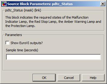
Determine the existence of DTCs which match the DTC type, DTC emissions severity and DTC state.
EXT_DIAG (Extended diagnostics library). (See Section 1.3, “Licensed Features”.)
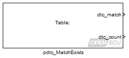
Given a DTC table, determine the existence of DTCs which match the block parameters DTC type, DTC emissions severity and DTC state. Indicate the existence, or otherwise via an output flag and a count.
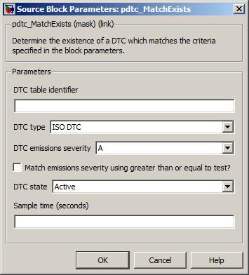
The name of the DTC table to act on (there must be a corresponding named table specified in a pdtc_Table block in the model).
Value type: String Calibratable: No A drop-down selection of the type of DTCs to match in the DTC table (specified by parameter DTC table identifier).
Value type: List Calibratable: No A drop-down selection of the emissions severity of the DTCs to match in the DTC table (specified by parameter DTC table identifier).
Value type: List Calibratable: No If this option is checked, the block will attempt to match DTCs that have an emissions severity greater than or equal to the DTC emissions severity. Otherwise, the block will attempt to match DTCs that have an emissions severity equal to the DTC emissions severity.
Value type: Boolean Calibratable: No A drop-down selection of the state of the DTCs to match in the DTC table (specified by parameter DTC table identifier).
Value type: List Calibratable: No The periodicity of the block execution in seconds.
Range: [0.001, 3600] seconds
Value type: Real Calibratable: No
Retain the DTC tables in non-volatile storage across power cycles.
See Section 6.1.40, “DTC memory update (pdtc_Memory)” for a detailed description.
Declares a table of diagnostic trouble codes (DTCs), that can be referred to by other blocks that wish to refer to a group of DTCs.
See Section 6.1.41, “DTC table definition (pdtc_Table)” for a detailed description.
The pdtc_TableCleared block can be used to signal when a diagnostic command to clear all DTCs (or a subset of DTCs) has been received for the specified table.
EXT_DIAG (Extended diagnostics library). (See Section 1.3, “Licensed Features”.)
Indication of whether the table's DTCs have been cleared since the block's previous execution. The value corresponds to which (if any) DTCs have been cleared since the last execution.
cleared J1939 Cleared Active DTCs (DM11) J1939 Cleared Previously Active DTCs (DM3) ISO Cleared All DTCs ($14) ISO Cleared Emissions DTCs ($04) 0 - - - - 1 - - - Y 2 - - Y - 3 - - Y Y 4 - Y - - 5 - Y - Y 6 - Y Y - 7 - Y Y Y 8 Y - - - 9 Y - - Y 10 Y - Y - 11 Y - Y Y 12 Y Y - - 13 Y Y - Y 14 Y Y Y - 15 Y Y Y Y Range: [0, 15]
Note
The KWP/UDS service $14 value is set regardless of the groupOfDTC parameter requested, even if that means only a subset of DTCs were actually cleared.
Value type: Integer Calibratable: No
The name of the DTC table to monitor (there must be a corresponding named table specified in a pdtc_Table block in the model).
Value type: String Calibratable: No The periodicity of the block execution. The sample time must be set explicitly - the block cannot be set to inherit a sample time from its parent. As the block's outport value is valid only until its next execution, the sample time should be sufficient for the value to be processed before this occurs.
Range: [0.001, 3600] seconds
Value type: Real Calibratable: No
Configure the ECU for ISO diagnostic communications.
EXT_DIAG (Extended diagnostics library). (See Section 1.3, “Licensed Features”.)
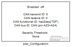
The ISO messaging protocol is a CAN based messaging system designed to pass information between vehicle network ECUs in real-time. The platform software handles communication with an external test tool using ISO 15765-2 based protocols (J1979, Keyword Protocol 2000-3, and ISO 14229-1 UDS).
There is support in the blockset for diagnostic trouble codes (see Section 4.6.6, “Fault support”).
The diagnostic services supported are drawn from three standards: SAE J1979 (ISO 15031-5, "OBD2"), Keyword Protocol 2000-3 (ISO 14230-3) and Unified Diagnostic Services (UDS, ISO 14229-1). They all work in the same way, with the first byte of each request message indicating the required service. Some services are the same (or compatible) in KW2000-3 and UDS. For a list of supported services, see the Extended Diagnostic Functions section.
The piso_Configuration block configures the ECU's behaviour when handling ISO messages. This includes selecting which CAN bus for ISO messaging, specifying the transmit and receive message IDs, as well as other parameters that adjust the amount of memory set aside for processing ISO messages.
If a piso_Configuration block is not present in the model, or if it is but the Enable ISO diagnostics parameter is not set, then ISO support is disabled.
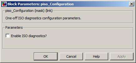
Enables/disables ISO messaging.
Value type: Boolean Calibratable: No The unique CAN identifier for the ISO messages transmitted by the system.
For standard OBD, ISO 15765-4 requires a value in the hex range 7E8 to 7EF for 11-bit IDs (the value being the physical receive ID plus 8), or 18DAF1xx for 29-bit IDs, where xx is the ECU 'source address' in J1939 terms.
Range: [0, 2047] if standard identifier
Range: [0, 536870911] if extended identifier
Value type: Integer Calibratable: No Enables/disables the use of an extended ISO transmit message CAN identifier.
Value type: Boolean Calibratable: No The unique CAN identifier for the ISO messages received by the system.
For standard OBD, ISO 15765-4 requires a value in the hex range 7E0 to 7E7 for 11-bit IDs (the value being the physical response ID minus 8), or 18DAxxF1 for 29-bit IDs, where xx is the ECU 'node address' in J1939 terms.
Range: [0, 2047] if standard identifier
Range: [0, 536870911] if extended identifier
Value type: Integer Calibratable: No Enables/disables the use of an extended ISO receive message CAN identifier.
Value type: Boolean Calibratable: No The global CAN identifier for ISO messages received by all participating ECUs in the vehicle.
For standard OBD, ISO 15765-4 requires a value of 7DF hex for an 11-bit ID system or 18DB33F1 for a 29-bit ID system.
The ECU reprogramming session expects a value of 7DF hex to be used. If a different value is specified by the application and the tester, reprogramming operations may not function as expected.
Range: [0, 2047] if standard identifier
Range: [0, 536870911] if extended identifier
Value type: Integer Calibratable: No A drop-down selection of CAN buses available for ISO messaging.
Value type: List Calibratable: No Size of ISO receive message buffer
The number of bytes for the ISO receive message buffer. This parameter allows the modeller to reduce the amount of RAM allocated to ISO messages, and therefore increase the RAM allocated to other functions of the ECU.
Range: [1, 4095]
Value type: Integer Calibratable: No Size of ISO transmit message buffer
The number of bytes for the ISO transmit message buffer. This parameter allows the modeller to reduce the amount of RAM allocated to ISO messages, and therefore increase the RAM allocated to other functions of the ECU.
Range: [1, 4095]
Value type: Integer Calibratable: No A drop-down selection of the emissions severity level at which a DTC should be considered "emissions related". This allows the modeller to combine "emissions related" and other DTCs within the same system.
Value type: List Calibratable: No Number of periodic identifiers
PIDs for automatic periodic sending must be in the 0xF2nn identifier range. Of those, this parameter is the maximum number that the platform will allow to be simultaneously requested by the test tool for automatic periodic transmission while the application is running via UDS service $2A. Leave at zero if service $2A support is not required, to save RAM.
Range: [0, 254]
Value type: Integer Calibratable: No Periodic identifier transmission base period
The "fast" target rate for PIDs requested for automatic transmission via UDS service $2A in milliseconds. The "medium" rate is 2x this period, and the "slow" rate is 4x this period. The platform will send PIDs more slowly than the target rate if this target cannot be met due to the PID size and transport protocol delays.
Range: [20, 65530]
Value type: Integer Calibratable: No Number of dynamically defined identifier buffers
The number of internal buffer slots allocated for the construction of dynamically-defined PIDs via UDS service $2C. If necessary one large PID definition may straddle several internal buffers. Leave at zero if service $2C support is not required, to save RAM.
Range: [0, 255]
Value type: Integer Calibratable: No If checked, this option allows the user to override the standard message response to J1979 service requests $03, $07 and $0A. Note that this override option should only be used in exceptional circumstances where it is understood that the resultant message responses will deviate from the J1979 standard.
Value type: Boolean Calibratable: No A drop-down selection of the override to apply to a J1979 service request $03 response. Only available if the Override J1979 standard? parameter is checked. Note that the platform also provides a calibration to override the response at runtime.
Value type: List Calibratable: No A drop-down selection of the override to apply to a J1979 service request $07 response. Only available if the Override J1979 standard? parameter is checked. Note that the platform also provides a calibration to override the response at runtime.
Value type: List Calibratable: No A drop-down selection of the override to apply to a J1979 service request $0A response. Only available if the Override J1979 standard? parameter is checked. Note that the platform also provides a calibration to override the response at runtime.
Value type: List Calibratable: No
Configure whether sensitive services are available and related SecurityAccess settings.
EXT_DIAG (Extended diagnostics library). (See Section 1.3, “Licensed Features”.)
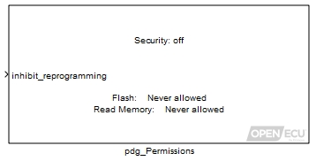
Certain UDS/KWP2000 services can be restricted to protect your ECU from having unauthorised changes or having its contents read out over the diagnostic link.
The relevant services can either be completely disallowed, or allowed only if the required seed-key security exchange has been passed successfully. (The options are detailed below.)
Even if flash reprogramming via UDS is allowed, you may wish to disable this facility if run-time circumstances are not appropriate (e.g. vehicle moving or engine running). The 'inhibit_reprogramming' inport allows you to control whether reprogramming is permitted at run time.

If enabled, the platform will attempt to use a C code function that implements your own custom security algorithm, whenever it receives the SecurityAccess ($27) service request from the tool. The security algorithm is also used in programming mode (i.e. by the boot loader) so that access to the ECU can be controlled even if the application has been erased, for subsequent programming attempts.
See Notes section at the end of this block help for more detail on how to implement the security function.
Value type: Boolean Calibratable: No Used to control whether UDS protocol flash reprogramming of the application code and/or calibration is allowed at all, and if so what SecurityAccess must be achieved first (if any). The options are:
Allowed without security: programming is always allowed, and no SecurityAccess exchange is required first.
Allowed if any security level attained: programming is only allowed if a SecurityAccess seed-key exchange has been passed successfully, but it does not matter which security level (LEV_SAT_RSD in the UDS standard) was negotiated.
Allowed if specified security level(s) attained: programming is only allowed if a SecurityAccess seed-key exchange has been passed successfully, and the security level (LEV_SAT_RSD in the UDS standard) was negotiated is one specified in the list (next parameter down).
Never allowed: programming is never permitted via UDS, regardless of SecurityAccess exchanges.
Value type: List Calibratable: No Security level(s) [for flash reprogramming]
This parameter only becomes visible if Allowed if specified security level(s) attained is selected above. Specify one or more values of the seed-key security level (LEV_SAT_RSD in the UDS standard) at which flash programming should be permitted. The levels must be odd values as used in the requestSeed request. (The corresponding level in the sendKey message is an even number equal to LEV_SAT_RSD + 1.)
Range: [1, 125] (odd numbers only)
Value type: Integer (scalar or vector) Calibratable: No This is very similar to the parameter which selects the allowed access for UDS flash reprogramming, but this time controls access to ECU memory via the ReadMemoryByAddress service ($23). See above for options.
Value type: List Calibratable: No Security level(s) [for ReadMemoryByAddress]
This is just like the corresponding parameter for flash reprogramming described in detail above, but this time relevant to ReadMemoryByAddress.
Value type: Integer (scalar or vector) Calibratable: No Whether ReadMemoryByAddress is allowed (ever) in a Default diagnosticSession.
Value type: Boolean Calibratable: No Whether ReadMemoryByAddress is allowed (ever) in an Extended diagnosticSession.
Value type: Boolean Calibratable: No Whether ReadMemoryByAddress is allowed (ever) in a Programming diagnosticSession.
Value type: Boolean Calibratable: No
You must implement your own security function to use seed-key security; it is not supplied by Pi Innovo, because it will be specific and confidential to you. The function must be written such that it does not depend on any statically allocated variables and does not call any functions, including functions inserted by the compiler for math utilities for example. This is to ensure that it is fully relocatable, which is required for it to run as part of the boot loader in reprogramming mode, as well as in normal application mode.
To add your function to the build, place the C file alongside the model, and then instruct RTW to include it in the build by using the Custom Code... Include list of additional:... Source files option, alongside other model configuration and build options in the Code Generation/Real-Time Workshop section (the exact menu item depends on MATLAB version).
Alternatively, you can compile your C code to make an object (.o) file and specify it in the Libraries option nearby. This is useful if you wish to be cautious with confidentiality by avoiding application-builders needing to have the C source code available.
Warning
If the auto-coder settings are switched, e.g. from Simulink Coder to Embedded Coder, this setting will need to be reconfigured.
The function name for the security algorithm and the second empty function that marks the end of it are fixed. If they are missing, a linker error will be reported. A complete example block of code is presented below, in which the "secret" algorithm is to reverse the order of the two seed bytes to form the correct key:
#include "openecu.h"


/*****************************************************************************
 *  Purpose: Called by the library when UDS/KW2000 diagnostic security access
 *           is required.
 *  Returns: Return code to send to tool on error, otherwise zero if OK.
 *  Notes:   Code is copied to nonvolatile memory and must be relocatable. It
 *           must not call any functions (including compiler arithmetic
 *           utilities).
 *****************************************************************************
 */
U8 psc_diag_security_callback
(
    const U8*  pdgf_request_message,      /* The received unpacked request message */
    U16        pdgf_request_message_len,  /* Total byte length of request message  */
    U8*        pdgf_seed_buffer,          /* Place seed here, or access it when computing correct key */
    U8*        pdgf_seed_len,             /* Specify your seed length (in bytes) here (max 8 bytes) */
    U32        pdgf_random                /* Pseudorandom number you may use to generate seed */
)
{

    if (pdgf_request_message_len < 2)
    {
        return 0x13; /* invalid length */
    }

    switch (pdgf_request_message[1])
    {
    case 0x03: /* a requestSeed value we choose to support */
        /* Set up the seed bytes, here using the provided random number */
        pdgf_seed_buffer[0] = (U8) pdgf_random & 0xff;
        pdgf_seed_buffer[1] = (U8) (pdgf_random >> 8);
        *pdgf_seed_len = 2;
        return 0;
        break;
    case 0x04: /* corresponding sendKey value */
        if ((pdgf_request_message_len == 4) &&
            (pdgf_request_message[2] == pdgf_seed_buffer[1]) &&
            (pdgf_request_message[3] == pdgf_seed_buffer[0])   )
        {
            /* security passed -- bytes reversed! */
            return 0;
        }
        else
        {
            return 0x35; /* invalid key */
        }
        break;
    default:
        return 0x12; /* unsupported parameters */
        break;
    }
}

/*****************************************************************************
 *  Purpose: Marks the end of the security function above.
 *  Returns: None.
 *  Notes:   Must be placed immediately after the security function. The
 *           platform uses this to calculate the size of the security function
 *           when relocating it to non-volatile memory for use in
 *           reprogramming mode.
 *****************************************************************************
 */
void psc_diag_security_end
(
    void
)
{
}
UDS service $19 ExtendedDataRecord configuration.
EXT_DIAG (Extended diagnostics library). (See Section 1.3, “Licensed Features”.)

Extended data records convey status information associated with a DTC. The information is retrieved at the time of the request. This block allows the assignment of DTCExtendedDataRecordNumbers within the manufacturer specific range [1,143] as well as the range reserved for legislated OBD DTCExtendedDataRecords [144, 239].
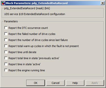
Report the DTC occurrence count
If enabled, the platform will report a one byte extended data record containing the DTC occurrence count.
Value type: Boolean Calibratable: No Occurrence count DTCExtendedDataRecordNumber
This field specifies the DTCExtendedDataRecordNumber that is used to identify the occurrence count.
Range: [1,239]
Value type: Integer Calibratable: No Report the failed number of drive cycles
If enabled, the platform will report a one byte extended data record containing the number of drive cycles in which the test has failed. The record is only available when the DTC is pending.
Value type: Boolean Calibratable: No Failed drive cycles DTCExtendedDataRecordNumber
This field specifies the DTCExtendedDataRecordNumber that is used to identify the count of drive cycles in which the test has failed.
Range: [1,239]
Value type: Integer Calibratable: No Report the number of drive cycles since last failure
If enabled, the platform will report a one byte extended data record containing the number of drive cycles since the last test failure. The record is only available when the DTC is active.
Value type: Boolean Calibratable: No Drive cycles since failure DTCExtendedDataRecordNumber
This field specifies the DTCExtendedDataRecordNumber that is used to identify the number of drive cycles since the last test failure.
Range: [1,239]
Value type: Integer Calibratable: No Report total warm up cycles in which the fault has not been present
If enabled, the platform will report a one byte extended data record containing the number of warm-up cycles in which the fault has not been present. The record is reset upon the DTC state transition to the previously active state.
Value type: Boolean Calibratable: No Warm up cycles DTCExtendedDataRecordNumber
This field specifies the DTCExtendedDataRecordNumber that is used to identify the number of warm-up cycles in which the fault has not been present.
Range: [1,239]
Value type: Integer Calibratable: No If enabled, the platform will report a two byte extended data record containing the total time (resolution 1min/bit) left until derate will occur. The record is only available while the DTC is in the active state and the DTC attribute 'has-torque-derate' is true.
Value type: Boolean Calibratable: No Time until derate DTCExtendedDataRecordNumber
This field specifies the DTCExtendedDataRecordNumber that is used to identify the total time left until derate will occur.
Range: [1,239]
Value type: Integer Calibratable: No Report total time in state 'previously active'
If enabled, the platform will report a two byte extended data record containing the total time (resolution 0.2hr/bit) that the DTC has been in the previously active state.
Value type: Boolean Calibratable: No Time in state 'previously active' DTCExtendedDataRecordNumber
This field specifies the DTCExtendedDataRecordNumber that is used to identify the total time that the DTC has been in the previously active state.
Range: [1,239]
Value type: Integer Calibratable: No Report total time in state 'active'
If enabled, the platform will report a two byte extended data record containing the total time (resolution 0.2hr/bit) that the DTC has been in the active state.
Value type: Boolean Calibratable: No Time in state 'active' DTCExtendedDataRecordNumber
This field specifies the DTCExtendedDataRecordNumber that is used to identify the total time that the DTC has been in the active state.
Range: [1,239]
Value type: Integer Calibratable: No Report the engine running time
If enabled, the platform will report a two byte extended data record containing the total time (resolution 0.2hr/bit) that the engine has been running while the DTC's fault has not been present and the DTC has been in the 'active' or 'previously active' state.
Value type: Boolean Calibratable: No Engine running time DTCExtendedDataRecordNumber
This field specifies the DTCExtendedDataRecordNumber that is used to identify the total time that the engine has been running while the DTC has been in the 'active' or 'previously active' state.
Range: [1,239]
Value type: Integer Calibratable: No
Communicates UDS service 0x31 (routine control) IO to and from a diagnostic scan tool.
EXT_DIAG (Extended diagnostics library). (See Section 1.3, “Licensed Features”.)
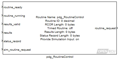
Routines can be used to allow a diagnostic tool to perform a custom function within the ECU. For example, a function of the ECU can be started and stopped from the diagnostic tool, or a set of values can be written to or read from ECU memory. The actual routine is defined by the application software.
Flag from the application to inform the platform that the routine is able to run. If this inport is FALSE, the platform will send a negative response to the diagnostic tool if this routine is requested, and the routine_request outport will output
noRequest.Value type: Boolean Flag from the application to inform the platform that the routine is running.
Value type: Boolean Flag from application to inform the platform that the data supplied at results inport is valid (i.e. the routine has been run at least one time, and the results are considered valid by the application.) If results are not used for this routine,set Results Length to 0 in the dialog, and ground this inport.
Value type: Boolean This is the array of bytes that will be transmitted to the diagnostic scan tool when service 0x31 is requested with subfunction 0x03 (requestRoutineResults) AND results_valid is TRUE. If results will not be used, set Results Length to 0 in the dialog, and ground this inport.
Value type: Array This is an optional array of bytes that will be transmitted to the diagnostic scan tool in response to any service 0x31 request. If a status record is not used, set Status Record Length in the dialog to 0 and ground this inport.
Value type: Array This inport is only used in simulation and only appears if Provide Simulation Input is ticked in the dialog. During simulation, any value supplied to this inport is immediately copied to the routine_request outport.
Value type: U8 This inport is only used in simulation and only appears if Provide Simulation Input is ticked in the dialog. During simulation, any array supplied to this inport is immediately copied to the rcor outport.
Value type: Array
Indicates the routine request sub-function that was received from the diagnostic scan tool. Note: the received routine request sub-function will only be output for one sample.
Table 8.4. RoutineControl request sub-function
Sub-function Name Value Description noRequest 0x00 Indicates that no request has been received from the diagnostic tool. startRoutine 0x01 Indicates that the application must start the routine. stopRoutine 0x02 Indicates that the application must stop the routine.
Note: requestRoutineResults (0x03) is handled automatically by the platform. Thus, the routine_request outport will never be 0x03.
Value type: U8 Provides the optional routineControlOptionRecord byte array to the application. This outport only appears if the dialog entry RCOR Length is non-zero.
Value type: Array

A unique routine ID that will be used by the diagnostic tool to identify this routine. Note: routine IDs 0x0202, 0x0203, 0xFF00, and 0xFF01 are reserved by the platform and cannot be used by the application.
Value type: U16 Calibratable: No Defines the number of bytes in the optional routineControlOptionRecord byte array. Set to 0 if the routine does not use a routineControlOptionRecord.
Value type: U16 Calibratable: No If ticked, this routine is a "Method B" (timed) routine, and will therefore stop on its own (without a stopRoutine request). If unticked, this routine is a "Method A" (untimed) routine, which requires a stopRoutine request to stop the routine. See ISO 14229-1 section 13 for further details regarding Method A vs. Method B routines.
Even if ticked, the routine must handle a stopRoutine request to allow the diagnostic tool to stop the routine if necessary.
Value type: Boolean Calibratable: No Defines the number of bytes in the results array. Set to 0 if the routine does not use results.
Value type: U16 Calibratable: No Defines the number of bytes in the optional statusRecord array. Set to 0 if the routine does not use a statusRecord.
Value type: U16 Calibratable: No If ticked, two additional inports will be revealed. See sim_routine_request inport and sim_RCOR for further details.
Value type: Boolean Calibratable: No Defines the sample time that this block will use to check for incoming routine requests, and update outports. Must be a multiple of 0.001.
Value type: double Calibratable: No
Negative response codes to service $31 requests are handled automatically by the platform software. The following list gives the possible negative response codes and the situations in which they are sent.
subFunctionNotSupported (0x12): sent when the diagnostic tool requested a subfunction other than startRoutine (0x01), stopRoutine (0x02), or requestRoutineResults (0x03).
incorrectMessageLengthOrInvalidFormat (0x13): sent when the diagnostic tool sent a service $31 request message that is too short to contain a 16-bit routine ID.
conditionsNotCorrect (0x22): sent when the diagnostic tool sent a startRoutine request when routine_ready is FALSE.
requestSequenceError (0x24): This negative code can occur in one of 3 situations:
1) The diagnostic tool sends a requestRoutineResults command when results_valid is FALSE.
2) The diagnostic tool sends a startRoutine command for a routine that is already running.
3) The diagnostic tool sends a stopRoutine command for a routine that is not running.
requestOutOfRange (0x31): This negative code can occur if one of the following two situations occur:
1) The diagnostic tool sends a service $31 request for a routine ID that is not supported by the application or the platform.
2) The diagnostic tool sends a service $31 request with the the number of bytes in the optional routineControlOptionRecord that is different from what is defined in the RCOR Length dialog parameter.
Routine requests are handled according to the following state diagram
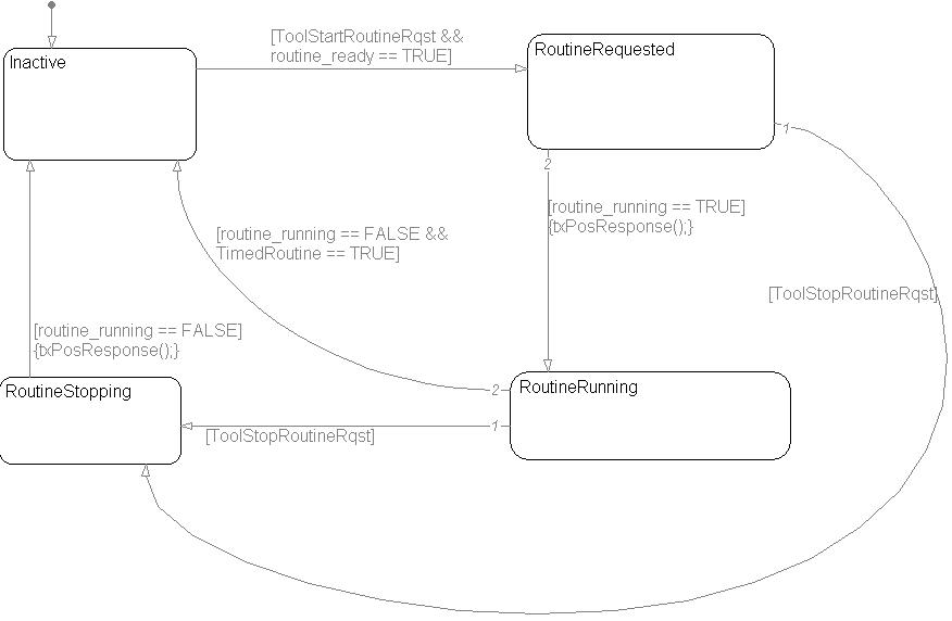
Important notes regarding the routine control state diagram:
1) If the application specifies that the routine is ready AND a startRoutine request is received from the tool, the application MUST start the routine. Otherwise, the routine state machine will stay in the RoutineRequested state until a stopRoutine request is received for the same routine ID. Furthermore, the routine must be started within the amount of time to allow the response message to be transmitted within 1000 ms of when the diagnostic tool sent the request.
2) If a stopRoutine request is received from the diagnostic tool, the application MUST stop the routine. Otherwise, the routine control state machine will stay in the RoutineSopping state. Furthermore, the routine must be stopped within the amount of time to allow the response message to be transmitted within 1000 ms of when the diagnostic tool sent the request.
Some routines are handled by the platform without any input from the application. These routines have routine IDs that may not be used by the application. The reserved routine IDs are: 0x0202, 0x0203, 0xFF00, and 0xFF01.
Captures the current value of a parameter to internal memory or non-volatile memory for access by a diagnostic scan tool.
EXT_DIAG (Extended diagnostics library). (See Section 1.3, “Licensed Features”.)
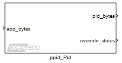
A PID is used to access the current value of an application parameter by a diagnostic scan tool. The access includes reading the parameter and if enabled over-riding the parameter. If the parameter is a non-volatile PID, this value can be written to non-volatile memory, and retained across power cycles.
Application supplied data which is to be accessed by a diagnostic scan tool via the associated PID.
Value type: Array Flag from application to write the data supplied at app_bytes to non-volatile memory. The memory write is triggered on a rising edge. This inport is only active when the Non-volatile storage parameter is ticked.
Value type: Boolean
When the PID data is being overridden at the request of the diagnostic scan tool, this outport gives the override data. When not overridden, this outport just copies what is entered at the app_bytes inport. Note that the size and dimensions of this outport are automatically set to match those of the app_bytes inport.
Value type: Array Indicates the ControlParameter status for an InputOutputControl diagnostic service. The values of the InputOutputControlParameter are specified as per the draft KW2000-3. The issued KW2000-3 standard does not specify the values. The draft KW2000-3 and UDS InputOutputControlParameter values do not match
Table 8.5. InputOutputControl Status (KW2000-3 draft)
IOControl Status Value Description returnControlToECU 0x00 Indicates that ControlParameter from InputOutputControl request from test tool was "return control to ECU", or this PID is not currently subject to IOControl. freezeCurrentState 0x05 Indicates that ControlParameter from InputOutputControl request from test tool was "freeze current state", indicating that this PID is currently subject to override by the tool. shortTermAdjustment 0x07 Indicates that ControlParameter from InputOutputControl request from test tool was "short term adjustment", indicating that this PID is currently subject to override by the tool.
Value type: Integer Flag to indicate if the value read from a non-volatile PID is valid. The non-volatile PID can be invalid, if it does not exist yet in non-volatile memory, as it has never been written before. It can also be invalid if the previous size in bytes does not match the currently read size. This flag indicates if the data in pid_bytes is valid. This outport is only active when the Non-volatile storage parameter is ticked.
Value type: Boolean The number of controlEnableMask bytes received in the most recent $2F request from the test tool. This outport is only active when the Number of controlEnableMask bytes expected parameter has a non-zero value.
Value type: uint8_T The controlEnableMask byte values received in the most recent $2F request from the test tool. This outport is only active when the Number of controlEnableMask bytes expected parameter has a non-zero value. Only the number of bytes indicated in the num_cem_recvd signal are valid; the rest are zeroed.
Value type: uint8_T vector
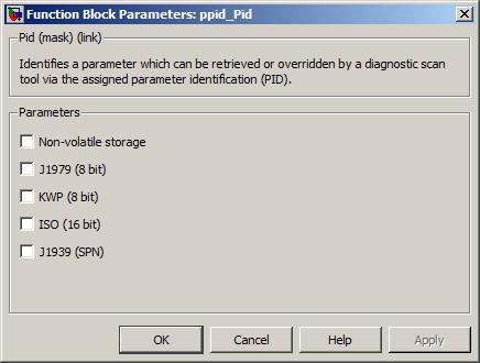
If ticked indicates the PID's value is to be preserved across power cycles thus it is stored in non-volatile memory
Value type: Boolean Calibratable: No If ticked, this parameter is accessible using the SAE J1979 protocol. A numeric box is unveiled upon ticking this box. In the unveiled numeric box enter the unique PID number. This parameter is not available if the Non-volatile storage parameter is ticked.
Value type: Boolean Calibratable: No If ticked, this parameter is accessible using the Keyword 2000-3 protocol. A numeric box is unveiled upon ticking this box. In the unveiled numeric box enter a unique PID number.
Value type: Boolean Calibratable: No If ticked, this parameter is accessible using the ISO 14229-1 (UDS) protocol. Two additional parameters are unveiled upon ticking this box. In the unveiled numeric box enter the unique PID number. Tick the unveiled "ReadScalingByIdentifier (UDS $24) support" box if UDS $24 support is required. If this box is ticked, more options are unveiled: see below following "Resend input as output". NOTE: If ticked, the PID data is not altered in any way by the PID block. The UDS $24 scaling data is only used to describe the scaling done by the application prior to the PID block so the diagnostic tool can properly decode the data.
Value type: Boolean Calibratable: No If ticked indicates the PID represents a J1939 Suspect Parameter Number. A numeric box is displayed upon ticking this box. In the displayed numeric box enter the unique SPN number. Note that this parameter is only currently used to allow freeze frame data to be stored for a J1939 DTC, and to allow reading from and writing to non-volatile memory.
Value type: Boolean Calibratable: No This checkbox is only displayed when the J1939 (SPN) checkbox is ticked. It determines the format in which the SPN data is transmitted. If ticked, the SPN data is treated as alphanumeric data with most significant byte transmitted first; otherwise it is transmitted with least significant byte first.
Value type: Boolean Calibratable: No If ticked indicates a string PID. A box to enter the string is displayed upon ticking this box. The entered string needs to be enclosed with single apostrophes. Note when using a string PID with non-volatile memory, the value of the string will only be written during initialisation.
Value type: Boolean Calibratable: No If ticked allows the diagnostic scan tool to override the PID. Leave unticked to deny the diagnostic scan tool the ability to override the PID. Not applicable for non-volatile PIDs.
Value type: Boolean Calibratable: No For a PID value which is being overridden by a diagnostic scan tool, two options exist for what value to report back to the diagnostic scan tool in response to a read data by identifier ($22) command. Not applicable for non-volatile PIDs.
- Unticked - Responds with the application value written to the PID.
- Ticked - Responds with the overridden value.
Value type: Boolean Calibratable: No Number of controlEnableMask bytes expected
If set to a non-zero value, the PID will accept additional input bytes as part of a $2F service request, and these are assumed to be controlEnableMask bytes. These are made available via the outports num_cem_recvd and cem_bytes.
It is the responsibility of the application to act appropriately on any controlEnableMask bytes, e.g. by restricting the override of physical outputs only to selected signals.
Value type: Integer Calibratable: No Part of ReadScalingByIdentifier support. Enter the number of data bytes that will be stored by this PID. This is the number of data bytes of the PID data, NOT the number of scaling bytes.
Value type: Integer Calibratable: No Part of ReadScalingByIdentifier support. A drop-down selection of data types as defined in ISO-14229.
Value type: List Calibratable: No Part of ReadScalingByIdentifier support. If ticked, indicates that a scaling formula will be transmitted with the scaling information. A "Formula Type" drop-down will be unveiled where the formula type must be specified. Additionally, numeric boxes will be unveiled where the formula coefficients must be entered.
Value type: Boolean Calibratable: No Part of ReadScalingByIdentifier support. If ticked, indicates that engineering units will be transmitted with the scaling information. A "Units" drop-down will be unveiled where the engineering units must be specified. Additionally, a "Use Unit Prefix" check-box will be unveiled. If ticked, a unit prefix will be transmitted with the scaling information. A unit prefix drop-down will be unveiled where the unit prefix must be specified.
Value type: Boolean Calibratable: No Specify state and connection type?
Part of ReadScalingByIdentifier support. If ticked, indicates that state and connection information (such as active high/low, pull-up/down circuitry, etc.) will be transmitted with the scaling information. Four drop-downs will be unveiled where the state and connection information must be specified.
Value type: Boolean Calibratable: No Part of ReadScalingByIdentifier support. This field will be unveiled if the "Scaling Data Type" drop-down is set to "F: Manually enter scaling bytes". This field allows the user to manually specify all of the scaling bytes that will be sent by the test tool. Scaling bytes must be entered as a comma-separated list of decimal integers from 0 to 255.
Value type: Array Calibratable: No Scaling Bytes Sent To Test Tool
Part of ReadScalingByIdentifier support. This read-only field displays the scaling bytes that will be transmitted when service $24 is requested.
Value type: String Calibratable: No
Certain PIDs are handled by the platform and should not be defined by the application using this block. In particular, the J1979 standard defines PIDs $00, $20, $40, etc. to be bitfields defining what other PIDs are supported in various contexts. These PIDs are handled directly by the platform in response to the different J1979 service messages that request them. Similarly, PID 0x02 is defined in the J1979 standard to identify the DTC that caused a freeze frame to be stored, and since this also depends on the context (as to the identity of the freeze frame in question) this too is handled directly by the platform.
This block outputs a raw byte value to represent the input with the scaling applied.
EXT_DIAG (Extended diagnostics library). (See Section 1.3, “Licensed Features”.)
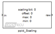
A PID value is usually stored in the ECU (server) in a finite number of bytes with an associated scaling. This scaling is common to both the client (diagnostic scan tool) and server.
The scaling block has been added as an aid to encoding a PID value with a scaling.
As such it is envisaged that the output of this block will feed into the input of ppid_Pid.
The scaling applied by this block follows the form of raw = (in - Scaling offset
)/ Scaling/bit
Note this block does not support multi-packed PIDs such as PID $01 of SAE J1979.
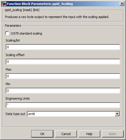
If ticked a drop down list of standard J1979 scalings is revealed. The scalings in the list are as per Annex B of issue 7 of ISO15031-5 (SAE J1979).
Value type: List Calibratable: No Numeric field to enter the scaling/bit.
For example a value of 0.25 in this field would result in 4 being output (assuming the offset is set to 0) from this block when the input is 1.
Value type: Real Calibratable: Yes, offline Numeric field to enter the scaling offset.
For example with a value of 0.25 set in the scaling/bit field and this field set to 0.5, would result in 2 being output from this block when the input is 1.
Value type: Real Calibratable: Yes, offline Numeric field to enter the maximum value of the input. An input value exceeding the maximum value is clipped to the maximum value prior to the scaling being applied.
Value type: Real Calibratable: Yes, offline Numeric field to enter the minimum value of the input. An input value falling below the minimum value is clipped to the minimum value prior to the scaling being applied.
Value type: Real Calibratable: Yes, offline String field to the engineering units associated with the scaling. The string in this field should be enclosed with single apostrophes.
Value type: String Calibratable: No A drop down list of the supported data types out. The supported data types are:
- uint8
- uint16
- uint32
Value type: List Calibratable: No
Captures a list of specified parameters upon the occurrence of an active DTC. The captured parameter values are stored for access by a diagnostic scan tool.
EXT_DIAG (Extended diagnostics library). (See Section 1.3, “Licensed Features”.)
Freeze Frame — Generic
A Freeze Frame is a snapshot of parameter values recorded at the time a diagnostic trouble code (DTC) was captured.
Note: non-volatile PIDs are not supported in freeze frames. If a freeze frame is defined by the application to contain a non-volatile PID, this PID is ignored by the PFF feature when capturing or accessing the freeze frame data.
The following diagram mirrors the finite state machine for the fault state for a DTC (see platform OBD state machine). In the diagram the transition conditions have been removed to aid clarity. The diagram highlights the transitions that cause a freeze frame instance to be captured and deleted.
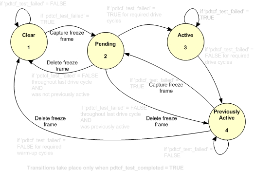
Once captured, the freeze frame instance is stored in non-volatile memory. As depicted in the diagram above, it is possible for multiple instances of a freeze frames associated with a single DTC to be stored in non-volatile memory.
When a DTC's fault state transitions to "Cleared" all instances of stored freeze frames associated with the DTC are deleted from non-volatile memory.
Note: The DTC occurrence count in the freeze frame may be out of sync when DTC becomes Active
Freeze Frame - ISO (J1979)
Freeze frame numbering is used by J1979 to report back to the scan tool the DTC that caused freeze frame capture and to read back the stored freeze frame instance(s). Numbering of freeze frame instances stored in non-volatile memory is sequential with the earliest captured freeze frame numbered as 0. As per J1979 numbering of freeze frames has an upper limit of 255.
Note: J1979 freeze frames are only captured for emissions related DTCs.
Freeze Frame - Snapshot (UDS)
UDS snapshot freeze frames follow the same capture rules as other freeze frame types; however, snapshots do not follow the same deletion rules. Snapshots captured as a result of a particular DTC are still deleted when the associated DTC transitions to clear; however, snapshots are not deleted when the DTC transitions from pending to previously active. Snapshot storage gives preference to the first and the most recent occurrence of a particular DTC. The snapshot captured as a result of the first occurrence of a DTC is assigned DTCSnapshotRecordNumber 0. The snapshot captured as a result of the next occurrence of a DTC is assigned DTCSnapshotRecordNumber 1 and is replaced upon subsequent occurrences of the DTC.
Note: A maximum of 2 UDS snapshots per DTC are stored at any given time.
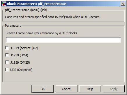
A unique freeze frame name is required in this field. The freeze frame name is referenced in the Simulink block of the DTC (see pdtc_DiagnosticTroubleCodeExt) that triggers the freeze frame.
Note the freeze frame name is used in the generated C code and as such should follow the C variable naming convention.
Value type: String Calibratable: No If ticked indicates the freeze frame complies with the J1979 standard.
Value type: Boolean Calibratable: No A vector calibration giving the list of PID identifiers for a J1979 freeze frame is placed in this field. The vector calibration needs to be defined in the data dictionary. The value field of the vector calibration in the data dictionary defines the PID identifers for the named freeze frame. However, all freeze frames should be cleared and the ECU power cycled after changing this calibration.
The vector calibration should be of type uint8_T.
The vector calibration should not have in excess of 255 elements.
Note that PIDs that are not defined in the application may be listed in the PIDs to capture field. The application will build, but the freeze frame may not behave as expected during runtime.
Note that Non-volatile PIDs may be listed in the PIDs to capture field. The application will build, but the freeze frame may not behave as expected during runtime.
Note that although no restriction is placed on when one may change this calibration, the correct procedure is to clear all freeze frame information and power cycle the ECU after any such change. Failure to follow this procedure could lead to anomalies in the freeze frame handling.
Value type: String Calibratable: Yes, offline and online If ticked indicates the freeze frame complies with J1939's DM4 freeze frame definition.
DM4 is composed of a list of mandatory SPNs and a manufacturer's list of SPN(s).
The mandatory SPNs are given by J1939-73 (FEB2010) as 899, 102, 190, 92, 110 and 84. The mandatory SPNs for DM4 have been hardcoded into the platform. As such when the OpenECU platform captures a DM4 freeze frame it always attempts to capture the mandatory SPN(s) regardless of the presence or absence of the SPN in the application. A mandatory SPN absent from the application will result in 0xFF(s) populating the data field allocated for the absent mandatory SPN in the returned DM4 message.
Value type: Boolean Calibratable: No The manufacturer's list of SPNs for a DM4 freeze frame are placed in this field. To enter the list of manufacturer SPNs use a vector calibration. The values of the SPNs are calibratable. However, all freeze frames should be cleared and the ECU power cycled after changing this calibration.
The vector calibration should be of type uint32_T.
The vector calibration should not have in excess of 255 elements.
A manufacturer SPN absent from the application will be ignored. The SPN will not be saved to non-volatile memory when the DM4 freeze frame is captured. The SPN's data will not appear in the returned DM message and no data fields within the returned DM4 are allocated to denote its presence.
Value type: String Calibratable: Yes, offline and online If ticked indicates the freeze frame complies with J1939's DM25 freeze frame definition.
As per J1939-73 only a single freeze frame definition can exist for DM25. The parameter list is specified by pff_Dm25FreezeFrame.
Value type: Boolean Calibratable: No If ticked indicates the freeze frame complies with the ISO 14229-1 (UDS) snapshot definition.
Value type: Boolean Calibratable: No A vector calibration giving the list of ISO PID identifiers for a snapshot is placed in this field. The vector calibration needs to be defined in the data dictionary. The value field of the vector calibration in the data dictionary defines the ISO PID identifiers for the named freeze frame. However, all freeze frames should be cleared and the ECU power cycled after changing this calibration.
The vector calibration should be of type uint16_T.
The vector calibration should not have in excess of 255 elements.
Value type: String Calibratable: Yes, offline and online
Specifies the list of SPN(s) to capture for a DM25 freeze frame.
EXT_DIAG (Extended diagnostics library). (See Section 1.3, “Licensed Features”.)

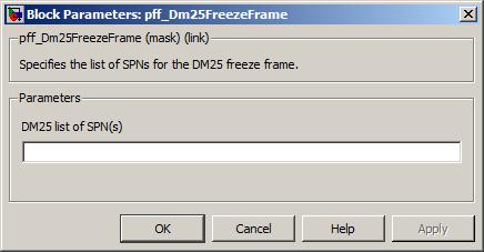
The list of SPN(s) for a DM25 freeze frame are placed in this field. To enter the list of SPN(s) use a vector calibration. The values of the SPN(s) are calibratable.
The vector calibration should be of type uint32_T.
The vector calibration should not have in excess of 255 elements.
A SPN absent from the application will be ignored. No data fields within the returned DM25 are allocated to denote its presence.
Value type: String Calibratable: Yes, offline and online
Specifies the amount of volatile (RAM) and non-volatile (flash) memory allocated for freeze frame storage.
EXT_DIAG (Extended diagnostics library). (See Section 1.3, “Licensed Features”.)
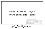
Specifies the amount of volatile (RAM) and non-volatile (flash) memory allocated for freeze frame storage.
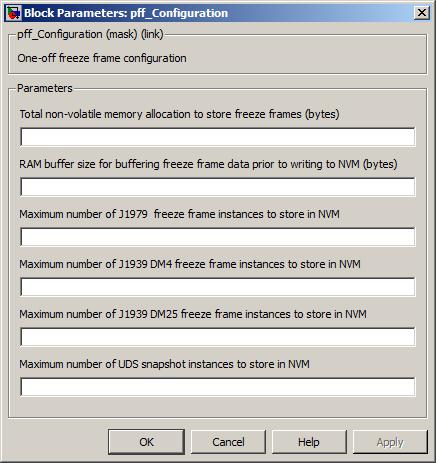
Total non-volatile memory allocation to store freeze frames (bytes)
This field specifies how much of non-volatile memory is allocated to storing instances of freeze frames. The allocation will be exclusively used for freeze frame storage. An appropriate size should be chosen to contain your application needs.
Captured freeze frames are stored in non-volatile memory using a file system. Each captured freeze frame is stored in an individual file. There is an overhead associated with each file stored in NVM. This overhead is 20 bytes plus whatever is required to round up to a multiple of 8 bytes. Thus on a freeze frame of 100 bytes, the overhead would be 20 bytes, whereas on a freeze frame of 101 bytes, the overhead would be 27. This overhead forms part of the total non-volatile memory allocation to store freeze frames, for instance if the application stores 10 freeze frame files each consisting of a 100 bytes of data the total NVM allocation specified here should be at least 1200 bytes.
Range: [0, 65535] bytes
Value type: Integer Calibratable: No RAM buffer size for buffering freeze frame data prior to writing to NVM (bytes)
RAM is allocated statically (at build time) in OpenECU. The specified RAM buffer size is used to store instances of freeze frames prior to writing to non-volatile memory. As such this field should at a minimum equal or exceed the largest freeze frame data size of all freeze frames in the application. Writing data to NVM is carried out in the background task as it takes time to complete. Should your application need to capture multiple freeze frame instances within a short interval this buffer should be sized appropriately to ensure the freeze frames are successfully written to NVM.
Note: an under sized RAM buffer may result in freeze frame instances not being captured.
Note: DM4 and DM25 of J1939 specify a max freeze frame data size of 1785 bytes.
Range: [0, 8191] bytes
Value type: Integer Calibratable: No Maximum number of J1979 freeze frame instances to store in NVM
This field specifies an upper limit on how many captured J1979 freeze frame instances can be stored in non-volatile memory (NVM).
Range: [0, 254]
Value type: Integer Calibratable: No Maximum number of J1939 DM4 freeze frame instances to store in NVM
This field specifies an upper limit to how many captured DM4 freeze frame instances can be stored in non-volatile memory.
Range: [0, 137]
Value type: Integer Calibratable: No Maximum number of J1939 DM25 freeze frame instances to store in NVM
This field specifies an upper limit to how many captured DM25 freeze frame instances can be stored in non-volatile memory.
Range: [0, 254]
Value type: Integer Calibratable: No Maximum number of UDS snapshot instances to store in NVM
This field specifies an upper limit to how many captured UDS snapshot instances can be stored in non-volatile memory.
Range: [0, 254]
Value type: Integer Calibratable: No
Configure the ECU for J1939 communications.
See Section 6.1.50, “J1939 configuration (pj1939_Configuration)” for a detailed description.
Configure a J1939 communications channel.
See Section 6.1.51, “J1939 channel configuration (pj1939_ChannelConfiguration)” for a detailed description.
Transmit a J1939/73 DM message to a specific destination address. Supports DM6, DM12, DM23, DM27, DM28, DM29, DM31, DM41, DM42, DM43, DM44, DM45, DM46, DM47, DM48, DM49, DM50, DM51, and DM52.
EXT_DIAG (Extended diagnostics library). (See Section 1.3, “Licensed Features”.)
A J1939/73 DM29 or DM30 message is a fixed-length message, transmitted by a network node to the specified destination address.
The simulation inport for the error_flag outport.
Value type: Boolean Calibratable: No Simulation value of the outport transport_errors.
Value type: Integer Calibratable: No Set to 1 to transmit a DM message, set to zero otherwise.
Range: 0 or 1.
Value type: Boolean Calibratable: No J1939 priority of the DM message to be transmitted.
Range: [0, 7]
Value type: Integer Calibratable: No J1939 destination address for the response message (usually the source address of the corresponding request). If use_dest_addr is false or a PDU2 message is shorter than 9 bytes, this value is ignored and the message is sent to the global address.
Range: [0, 254]
Value type: Integer Calibratable: No Whether to send the DM to a specified destination address. If false (0), the message will always be sent to the global address. Set to true (1) to allow the message to be sent to a specific destination address, such as the source address of a PGN request.
Range: 0 or 1.
Value type: Boolean Calibratable: No
Set to 1 when the DM message could not be buffered for transmission, or if a previous request to send a DM message has not completed.
Value type: Boolean Calibratable: No Saturated count of transport errors (timeout or aborts) for this message.
Range: [0, 255]
Value type: Integer Calibratable: No
The name of the DTC table to act on (there must be a corresponding named table specified in a pdtc_Table block in the model).
Value type: String Calibratable: No The logical J1939 channel on which to transmit. Must be a channel declared with a pj1939_ChannelConfiguration block.
Value type: Integer Calibratable: No Specifies the DTC data this block should send, by DM type.
Value type: Popup Calibratable: No
Indicates if a J1939/73 DM1 message has been received and decodes the contents of the lamp status.
See Section 6.1.52, “J1939 DM1 receive (pj1939_Dm1Receive)” for a detailed description.
Decodes the contents of the last received J1939-73 DM1 message based on specified DTC data.
See Section 6.1.53, “J1939 DM1 decode DTC (pj1939_Dm1DecodeDtc)” for a detailed description.
Transmit a J1939-73 DM1 message containing the DTCs with an active state from a DTC table.
See Section 6.1.54, “J1939 DM1 transmit (pj1939_Dm1Transmit)” for a detailed description.
Indicates if a J1939-73 DM2 message has been received and decodes the contents of the lamp status.
See Section 6.1.55, “J1939 DM2 receive (pj1939_Dm2Receive)” for a detailed description.
Decodes the contents of the last received J1939-73 DM2 message based on specified DTC data.
See Section 6.1.56, “J1939 DM2 decode DTC (pj1939_Dm2DecodeDtc)” for a detailed description.
Transmit a J1939/73 DM2 message containing the DTCs with a previously active state from a DTC table.
See Section 6.1.57, “J1939 DM2 transmit (pj1939_Dm2Transmit)” for a detailed description.
Transmit a J1939/73 DM4 message containing freeze frame data.
EXT_DIAG (Extended diagnostics library). (See Section 1.3, “Licensed Features”.)
The simulation inport for the error_flag outport.
Value type: Boolean Calibratable: No Simulation value of the outport transport_errors.
Value type: Integer Calibratable: No Set to 1 to transmit a DM4 message, set to zero otherwise.
Range: 0 or 1.
Value type: Boolean Calibratable: No J1939 priority of the DM4 message to be transmitted.
Range: [0, 7]
Value type: Integer Calibratable: No J1939 destination address for the DM4 message (This could be the source address of the corresponding PGN request, or the global address (255) if the request was sent to the global address). If use_dest_addr is false or a PDU2 message is shorter than 9 bytes, this value is ignored and the message is sent to the global address.
Range: [0, 255]
Value type: Integer Calibratable: No Whether to send the DM4 to a specified destination address. If false (0), the message will always be sent to the global address. Set to true (1) to allow the message to be sent to a specific destination address, such as the source address of a PGN request.
Range: 0 or 1.
Value type: Boolean Calibratable: No
Set to 1 when the DM4 message could not be buffered for transmission, or if a previous request to send a DM4 message has not completed.
Value type: Boolean Calibratable: No Saturated count of transport errors (timeout or aborts) for this message.
Range: [0, 255]
Value type: Integer Calibratable: No
The logical J1939 channel on which to transmit. Must be a channel declared with a pj1939_ChannelConfiguration block.
Value type: Integer Calibratable: No
Transmit a J1939/73 DM5 message containing the diagnostic readiness 1 data.
EXT_DIAG (Extended diagnostics library). (See Section 1.3, “Licensed Features”.)
A J1939/73 DM5 message is a fixed length message transmitted by a network node to the global network address. The DM5 message contents detail the diagnostic readiness data (part 1). As the message is made up from data calculated and stored internally within the platform, direct support is provided (rather than using the pj1939_PgTransmit block).
The simulation inport for the error_flag outport.
Value type: Boolean Calibratable: No Set to 1 to transmit a DM5 message, set to zero otherwise.
Range: 0 or 1.
Value type: Boolean Calibratable: No J1939 priority of the DM5 message to be transmitted.
Range: [0, 7]
Value type: Integer Calibratable: No The OBD compliance that this controller/software combination meets (see J1939-73 section 5.7.5.3).
Range: [0, 255]
Value type: Integer Calibratable: No
The logical J1939 channel on which to transmit. Must be a channel declared with a pj1939_ChannelConfiguration block.
Value type: Integer Calibratable: No The name of the DTC table to act on (there must be a corresponding named table specified in a pdtc_Table block in the model).
Value type: String Calibratable: No
Decodes the contents of a received J1939/73 DM7 message.
EXT_DIAG (Extended diagnostics library). (See Section 1.3, “Licensed Features”.)
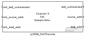
A J1939/73 DM7 message is a fixed length message. The purpose of a DM7 message is to command tests or last measured test results. Direct blockset support is provided (rather than relying on the pj1939_PgReceive block).
Refer to J1939-73 FEB2010 section 5.7.7 for details of the DM7 message.
The simulation value for the outport test_commanded.
Value type: Boolean Calibratable: No
Set to 1 (true) if a DM7 message has been received containing a commanded test which matches the Test identifier only (when parameter Test identifier is in the range [1, 64]) or if a DM7 message has been received containing a commanded test which matches the Test identifier and Suspect parameter number and Failure mode indicator parameters (when parameter Test identifier is in the range [247, 250]). Note that this is a one-shot pulse which will remain high only until the next block iteration.
Value type: Boolean Calibratable: No The source address of the DM7 message received.
Value type: Integer Calibratable: No The destination address of the DM7 message received.
Value type: Integer Calibratable: No
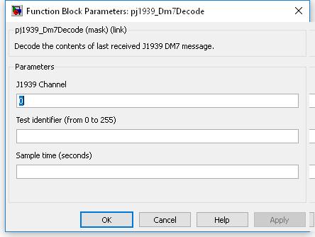
The logical J1939 channel on which to receive the request. Must be a channel declared with a pj1939_ChannelConfiguration block.
Value type: Integer Calibratable: No The value of the TID of the commanded test to match against. In the case where a DM30 response is required, the parameters Suspect parameter number, Failure mode indicator and Test identifier uniquely identify the commanded test. If a DM8 response is required then only the Test identifier is needed.
Range: [0, 255]
Value type: Integer Calibratable: No The value of the SPN of the commanded test to match against. The parameters Suspect parameter number, Failure mode indicator and Test identifier uniquely identify the commanded test. Only applicable if the Test identifier parameter is in the range [247, 250]. A DM30 response is required when the requested DM7 test consists of a valid SPN/FMI/TID combination.
Range: [0, 524287]
Value type: Integer Calibratable: No The value of the FMI of the commanded test to match against. The parameters Suspect parameter number, Failure mode indicator and Test identifier uniquely identify the commanded test. Only applicable if the Test identifier parameter is in the range [247, 250]. A DM30 response is required when the requested DM7 test consists of a valid SPN/FMI/TID combination.
Range: [0, 31]
Value type: Integer Calibratable: No The periodicity of the block execution.
Range: [0.001, 3600] seconds
Value type: Real Calibratable: No
Transmit a J1939/73 DM8 message containing the test results for one of the non-continuously monitored tests invoked using DM7. Refer to J1939-73 FEB2010 section 5.7.8 for details.
EXT_DIAG (Extended diagnostics library). (See Section 1.3, “Licensed Features”.)
A J1939/73 DM8 message is a variable length message. The DM8 message contains the test results corresponding to commanded tests received in DM7 messages (refer to the pj1939_Dm7Decode block). Test results data is supplied internally by the platform via the PPR feature (see the ppr_DiagnosticTestEntity block). As the message is variable in length and contains data maintained internally by the platform, direct support for the DM8 message is provided (rather than using the pj1939_PgTransmit block).
The simulation inport for the error_flag outport.
Value type: Boolean Calibratable: No Simulation value of the outport transport_errors.
Value type: Integer Calibratable: No Set to 1 to transmit a DM8 message, set to zero otherwise.
Range: 0 or 1.
Value type: Boolean Calibratable: No J1939 priority of the DM8 message to be transmitted.
Range: [0, 7]
Value type: Integer Calibratable: No The J1939 test identifier to use for obtaining test results to be transmitted in the DM8 message.
Range: [0, 255]
Value type: Integer Calibratable: No J1939 destination address for the DM8 message (This could be the source address of the corresponding PGN request, or the global address (255) if the request was sent to the global address). If use_dest_addr is false or a PDU2 message is shorter than 9 bytes, this value is ignored and the message is sent to the global address.
Range: [0, 255]
Value type: Integer Calibratable: No Whether to send the DM8 to a specified destination address. If false (0), the message will always be sent to the global address. Set to true (1) to allow the message to be sent to a specific destination address, such as the source address of a PGN request.
Range: 0 or 1.
Value type: Boolean Calibratable: No
Set to 1 when the DM8 message could not be buffered for transmission, or if a previous request to send a DM8 message has not completed.
Value type: Boolean Calibratable: No Saturated count of transport errors (timeout or aborts) for this message.
Range: [0, 255]
Value type: Integer Calibratable: No
The logical J1939 channel on which to transmit. Must be a channel declared with a pj1939_ChannelConfiguration block.
Value type: Integer Calibratable: No
Transmit a J1939/73 DM10 message containing the list of non-continuously monitored systems tests supported by the controller. Refer to J1939-73 FEB2010 section 5.7.10 for details.
EXT_DIAG (Extended diagnostics library). (See Section 1.3, “Licensed Features”.)
A J1939/73 DM10 message is a fixed length message transmitted by a network node
to the global network address. The DM10 message contains the list of
non-continuously monitored systems tests supported by the controller. The test identifier
to bit position mapping is defined in the DM10 bit position
parameter of the ppr_DiagnosticTestEntity block.
As the message is constructed from data held within the platform, direct support for the DM10
message is provided (rather than using the
pj1939_PgTransmit block).
The simulation inport for the error_flag outport.
Value type: Boolean Calibratable: No Set to 1 to transmit a DM10 message, set to zero otherwise.
Range: 0 or 1.
Value type: Boolean Calibratable: No J1939 priority of the DM10 message to be transmitted.
Range: [0, 7]
Value type: Integer Calibratable: No
The logical J1939 channel on which to transmit. Must be a channel declared with a pj1939_ChannelConfiguration block.
Value type: Integer Calibratable: No
Transmit a J1939/73 DM20 message containing the Performance Ratio Monitor data.
EXT_DIAG (Extended diagnostics library). (See Section 1.3, “Licensed Features”.)
A J1939/73 DM20 message is a variable length message, transmitted by a network node to the specified destination address. The DM20 message contents detail performance ratio data for the components being monitored. As the message is variable in length and the message is made up from data calculated and stored internally within the platform, direct support is provided (rather than using the pj1939_PgTransmit block).
The simulation inport for the error_flag outport.
Value type: Boolean Calibratable: No Simulation value of the outport transport_errors.
Value type: Integer Calibratable: No Set to 1 to transmit a DM20 message, set to zero otherwise.
Range: 0 or 1.
Value type: Boolean Calibratable: No J1939 priority of the DM20 message to be transmitted.
Range: [0, 7]
Value type: Integer Calibratable: No J1939 destination address for the response message (usually the source address of the corresponding request).
Range: [0, 254]
Value type: Integer Calibratable: No
Set to 1 when the DM20 message could not be buffered for transmission, or if a previous request to send a DM20 message has not completed.
Value type: Boolean Calibratable: No Saturated count of transport errors (timeout or aborts) for this message.
Range: [0, 255]
Value type: Integer Calibratable: No
The logical J1939 channel on which to transmit. Must be a channel declared with a pj1939_ChannelConfiguration block.
Value type: Integer Calibratable: No
Transmit a J1939/73 DM21 message containing the diagnostic readiness 2 data.
EXT_DIAG (Extended diagnostics library). (See Section 1.3, “Licensed Features”.)
A J1939/73 DM21 message is a fixed length message transmitted by a network node to the specified destination address. The DM21 message contents detail the diagnostic readiness data (part 2). Refer to J1939-73 Feb2010 section 5.7.21 for details. Direct support is provided (rather than using the pj1939_PgTransmit block).
The simulation inport for the error_flag outport.
Value type: Boolean Calibratable: No Set to 1 to transmit a DM21 message, set to zero otherwise.
Range: 0 or 1.
Value type: Boolean Calibratable: No J1939 priority of the DM21 message to be transmitted.
Range: [0, 7]
Value type: Integer Calibratable: No The accumulated count (in minutes) run by the engine while the MIL is activated. Refer to J1939-73 Feb2010 section 5.7.21.3 for details. The platform will limit the transmitted value to the range specified below.
Range: [0, 64255] minutes
Value type: Integer Calibratable: No The distance travelled (in kilometres) while the MIL is activated. Refer to J1939-73 Feb2010 section 5.7.21.1 for details. The platform will limit the transmitted value to the range specified below.
Range: [0, 64255] kilometres
Value type: Integer Calibratable: No The engine running time (in minutes) accumulated since emission related DTCs were cleared. Refer to J1939-73 Feb2010 section 5.7.21.4 for details. The platform will limit the transmitted value to the range specified below.
Range: [0, 64255] minutes
Value type: Integer Calibratable: No The distance accumulated (in kilometres) since emission related DTCs were cleared. Refer to J1939-73 Feb2010 section 5.7.21.2 for details. The platform will limit the transmitted value to the range specified below.
Range: [0, 64255] kilometres
Value type: Integer Calibratable: No J1939 destination address for the response message (usually the source address of the corresponding request).
Range: [0, 254]
Value type: Integer Calibratable: No
The logical J1939 channel on which to transmit. Must be a channel declared with a pj1939_ChannelConfiguration block.
Value type: Integer Calibratable: No
Transmit a J1939/73 DM24 message identifying supported SPNs.
EXT_DIAG (Extended diagnostics library). (See Section 1.3, “Licensed Features”.)
A J1939/73 DM24 message is a variable length message. It identifies which SPNs support Data Streams, Scaled Test Results, and Expanded Freeze Frames (DM25).
The Data Stream SPNs are simply those ppid_Pid blocks with SPN IDs defined. The Scaled Test Result SPNs are those defined in the ppr_DiagnosticTestEntity blocks. The DM25 SPNs are specified by the calibration identified in the pff_Dm25FreezeFrame block.
Note: for Data Stream SPNs the application still has to create the message responses for the corresponding PGNs itself, using the pj1939_PgTransmit block.
The simulation inport for the error_flag outport.
Value type: Boolean Calibratable: No Simulation value of the outport transport_errors.
Value type: Integer Calibratable: No Set to 1 to transmit a DM24 message, set to zero otherwise.
Range: 0 or 1.
Value type: Boolean Calibratable: No J1939 priority of the DM24 message to be transmitted.
Range: [0, 7]
Value type: Integer Calibratable: No J1939 destination address for the DM24 message (This could be the source address of the corresponding PGN request, or the global address (255) if the request was sent to the global address). If use_dest_addr is false or a PDU2 message is shorter than 9 bytes, this value is ignored and the message is sent to the global address.
Range: [0, 255]
Value type: Integer Calibratable: No Whether to send the DM24 to a specified destination address. If false (0), the message will always be sent to the global address. Set to true (1) to allow the message to be sent to a specific destination address, such as the source address of a PGN request.
Range: 0 or 1.
Value type: Boolean Calibratable: No
Set to 1 when the DM24 message could not be buffered for transmission, or if a previous request to send a DM24 message has not completed.
Value type: Boolean Calibratable: No Saturated count of transport errors (timeout or aborts) for this message.
Range: [0, 255]
Value type: Integer Calibratable: No
The logical J1939 channel on which to transmit. Must be a channel declared with a pj1939_ChannelConfiguration block.
Value type: Integer Calibratable: No
Request that a J1939 DM25 (expanded freeze frame) message is transmitted.
EXT_DIAG (Extended diagnostics library). (See Section 1.3, “Licensed Features”.)
A J1939/73 DM25 message is a variable length message, transmitted by a network node.
The simulation inport for the error_flag outport.
Value type: Boolean Calibratable: No Simulation value of the outport transport_errors.
Value type: Integer Calibratable: No Set to 1 to transmit a DM25 message, set to zero otherwise.
Range: 0 or 1.
Value type: Boolean Calibratable: No J1939 priority of the DM25 message to be transmitted.
Range: [0, 7]
Value type: Integer Calibratable: No J1939 destination address for the DM25 message (This could be the source address of the corresponding PGN request, or the global address (255) if the request was sent to the global address). If use_dest_addr is false or a PDU2 message is shorter than 9 bytes, this value is ignored and the message is sent to the global address.
Range: [0, 255]
Value type: Integer Calibratable: No Whether to send the DM25 to a specified destination address. If false (0), the message will always be sent to the global address. Set to true (1) to allow the message to be sent to a specific destination address, such as the source address of a PGN request.
Range: 0 or 1.
Value type: Boolean Calibratable: No
Set to 1 when the DM25 message could not be buffered for transmission, or if a previous request to send a DM25 message has not completed.
Value type: Boolean Calibratable: No Saturated count of transport errors (timeout or aborts) for this message.
Range: [0, 255]
Value type: Integer Calibratable: No
The logical J1939 channel on which to transmit. Must be a channel declared with a pj1939_ChannelConfiguration block.
Value type: Integer Calibratable: No
Transmit a J1939/73 DM26 message containing the diagnostic readiness 3 data.
EXT_DIAG (Extended diagnostics library). (See Section 1.3, “Licensed Features”.)
A J1939/73 DM26 message is a fixed length message. The DM26 message contents detail the diagnostic readiness data (part 3). Refer to J1939-73 Feb2010 section 5.7.26 for details. Direct support is provided (rather than using the. pj1939_PgTransmit block).
The simulation inport for the error_flag outport.
Value type: Boolean Calibratable: No Set to 1 to transmit a DM26 message, set to zero otherwise.
Range: 0 or 1.
Value type: Boolean Calibratable: No J1939 priority of the DM26 message to be transmitted.
Range: [0, 7]
Value type: Integer Calibratable: No J1939 destination address for the DM26 message (This could be the source address of the corresponding PGN request, or the global address (255) if the request was sent to the global address). If use_dest_addr is false or a PDU2 message is shorter than 9 bytes, this value is ignored and the message is sent to the global address.
Range: [0, 255]
Value type: Integer Calibratable: No Whether to send the DM26 to a specified destination address. If false (0), the message will always be sent to the global address. Set to true (1) to allow the message to be sent to a specific destination address, such as the source address of a PGN request.
Range: 0 or 1.
Value type: Boolean Calibratable: No The time (in seconds), since key-on, that the engine has been running. Refer to J1939-73 Feb2010 section 5.7.26.1 for details. The platform will limit the transmitted value to the range specified below.
Range: [0, 64255] seconds
Value type: Integer Calibratable: No The number of warm-up cycles since all DTCs were cleared. Refer to J1939-73 Feb2010 section 5.7.26.2 for details. The platform will limit the transmitted value to the range specified below.
Range: [0, 250]
Value type: Integer Calibratable: No
The logical J1939 channel on which to transmit. Must be a channel declared with a pj1939_ChannelConfiguration block.
Value type: Integer Calibratable: No
Transmit a J1939/73 DM30 message containing the scaled test results for the applicable test(s) requested in a DM7 message. Refer to J1939-73 Jul2013 section 5.7.30 for details.
EXT_DIAG (Extended diagnostics library). (See Section 1.3, “Licensed Features”.)
A J1939/73 DM30 message is a variable length message transmitted by a network node to the specified destination address. The DM30 message contents detail the scaled test results for the applicable test(s) requested in a DM7 message (handled by the associated pj1939_Dm7Decode block). As the message is variable in length and the data is derived from information maintained by the PPR platform feature (see block ppr_DiagnosticTestEntity, direct support is provided (rather than using the pj1939_PgTransmit block).
The simulation inport for the error_flag outport.
Value type: Boolean Calibratable: No Simulation value of the outport transport_errors.
Value type: Integer Calibratable: No Set to 1 to transmit a DM30 message, set to zero otherwise.
Range: 0 or 1.
Value type: Boolean Calibratable: No J1939 priority of the DM30 message to be transmitted.
Range: [0, 7]
Value type: Integer Calibratable: No The J1939 suspect parameter number to use for obtaining the test results to be transmitted in the DM30 message.
Range: [0, 524287]
Value type: Integer Calibratable: No J1939 destination address for the response message (should usually be the source address of the corresponding request, but the global address (255) if the request was sent to the global address).
Range: [0, 255]
Value type: Integer Calibratable: No
Set to 1 when the DM30 message could not be buffered for transmission, or if a previous request to send a DM30 message has not completed.
Value type: Boolean Calibratable: No Saturated count of transport errors (timeout or aborts) for this message.
Range: [0, 255]
Value type: Integer Calibratable: No
The logical J1939 channel on which to transmit. Must be a channel declared with a pj1939_ChannelConfiguration block.
Value type: Integer Calibratable: No Together with the spn and Failure Mode Indicator (FMI), this identifies the specific test for which results are required, to match the DTE values; or a special value of 246 (results for all tests) or 247 (all results for specified SPN only).
Range: [0, 255]
Value type: Integer Together with the spn and Test Identifier (TID), this identifies the specific test for which results are required, to match the DTE values; or a special value of 31 if a TID of 246 or 247 is requested.
Range: [0, 31]
Value type: Integer
Transmit a J1939/73 DM32 message containing the regulated exhaust emission level exceedance data. Refer to J1939-73 Feb2010 section 5.7.32 for details.
EXT_DIAG (Extended diagnostics library). (See Section 1.3, “Licensed Features”.)
A J1939/73 DM32 message is a variable length message transmitted by a network node to the specified destination address. The DM32 message contents detail the DTCs and associated timers related to a regulated exhaust emission level exceedance. Direct support is provided (rather than using the pj1939_PgTransmit block).
The simulation inport for the error_flag outport.
Value type: Boolean Calibratable: No Simulation value of the outport transport_errors.
Value type: Integer Calibratable: No Set to 1 to transmit a DM32 message, set to zero otherwise.
Range: 0 or 1.
Value type: Boolean Calibratable: No J1939 priority of the DM32 message to be transmitted.
Range: [0, 7]
Value type: Integer Calibratable: No J1939 destination address for the response message (usually the source address of the corresponding request).
Range: [0, 254]
Value type: Integer Calibratable: No
Set to 1 when the DM32 message could not be buffered for transmission, or if a previous request to send a DM32 message has not completed.
Value type: Boolean Calibratable: No Saturated count of transport errors (timeout or aborts) for this message.
Range: [0, 255]
Value type: Integer Calibratable: No
The logical J1939 channel on which to transmit. Must be a channel declared with a pj1939_ChannelConfiguration block.
Value type: Integer Calibratable: No The name of the DTC table to act on (there must be a corresponding named table specified in a pdtc_Table block in the model).
Value type: String Calibratable: No
Transmit a J1939/73 DM33 message. Refer to J1939-73 Feb2010 for details.
EXT_DIAG (Extended diagnostics library). (See Section 1.3, “Licensed Features”.)
A J1939/73 DM33 message is a variable length message transmitted by a network node to the specified destination address.
The simulation inport for the error_flag outport.
Value type: Boolean Calibratable: No Simulation value of the outport transport_errors.
Value type: Integer Calibratable: No Set to 1 to transmit a DM33 message, set to zero otherwise.
Range: 0 or 1.
Value type: Boolean Calibratable: No J1939 priority of the DM33 message to be transmitted.
Range: [0, 7]
Value type: Integer Calibratable: No J1939 destination address for the response message (usually the source address of the corresponding request).
Range: [0, 254]
Value type: Integer Calibratable: No
Set to 1 when the DM33 message could not be buffered for transmission, or if a previous request to send a DM33 message has not completed.
Value type: Boolean Calibratable: No Saturated count of transport errors (timeout or aborts) for this message.
Range: [0, 255]
Value type: Integer Calibratable: No
The logical J1939 channel on which to transmit. Must be a channel declared with a pj1939_ChannelConfiguration block.
Value type: Integer Calibratable: No
Transmit a J1939/73 DM34 message containing the NTE status data. Refer to J1939-73 Feb2010 section 5.7.34 for details.
EXT_DIAG (Extended diagnostics library). (See Section 1.3, “Licensed Features”.)
A J1939/73 DM34 message is a fixed length message transmitted by a network node to the specified destination address. The DM34 message contents detail the status of the engine operating in the NTE control areas for given pollutants such as NOx and PM. Direct support is provided (rather than using the pj1939_PgTransmit block).
The simulation inport for the error_flag outport.
Value type: Boolean Calibratable: No Set to 1 to transmit a DM34 message, set to zero otherwise.
Range: 0 or 1.
Value type: Boolean Calibratable: No J1939 priority of the DM34 message to be transmitted.
Range: [0, 7]
Value type: Integer Calibratable: No J1939 destination address for the response message (usually the source address of the corresponding request).
Range: [0, 254]
Value type: Integer Calibratable: No
The logical J1939 channel on which to transmit. Must be a channel declared with a pj1939_ChannelConfiguration block.
Value type: Integer Calibratable: No
The platform requires that the status of the various NTE areas is updated by the application. The pj1939_UpdateNteStatus block is provided for this purpose.
Transmit a J1939/73 DM35 message containing the transient fault status of DTCs, from a DTC table.
EXT_DIAG (Extended diagnostics library). (See Section 1.3, “Licensed Features”.)
A J1939/73 DM35 message is a variable length message. The DM35 message contents detail the transient fault status of diagnostic trouble codes. As the message is variable in length, direct blockset support is provided (rather than relying on the pj1939_PgTransmit block).
When the block executes, the DTC table is inspected for a change in transient fault status of DTCs. If any differ since the last time the block executed, a DM35 message is sent (when the minimum inter-message interval has elapsed). The purpose for this message is that of troubleshooting intermittent wiring problems ("wiggle test"). Refer to J1939-73 Feb2010 section 5.7.35 for details of the transmission rate and options.
The simulation inport for the error_flag outport.
Value type: Boolean Calibratable: No Simulation value of the outport transport_errors.
Value type: Integer Calibratable: No Set to 1 to start the transmission of DM35 messages. A rising edge on this inport causes DM35 messages to be transmitted either until key-off or the stop_transmission inport is set to 1.
Range: 0 or 1.
Value type: Boolean Calibratable: No Set to 1 to force the transmission of a DM35 message, regardless of whether any DTC has a change of transient fault status.
Range: 0 or 1.
Value type: Boolean Calibratable: No Set to 1 to stop the transmission of DM35 messages.
Range: 0 or 1.
Value type: Boolean Calibratable: No J1939 priority of the DM35 message to be transmitted.
Range: [0, 7]
Value type: Integer Calibratable: No J1939 destination address for the response message (usually the source address of the corresponding request).
Range: [0, 254]
Value type: Integer Calibratable: No
Set to 1 when the DM35 message could not be buffered for transmission, or if a previous request to send a DM35 message has not completed.
Value type: Boolean Calibratable: No Saturated count of transport errors (timeout or aborts) for this message.
Range: [0, 255]
Value type: Integer Calibratable: No
The logical J1939 channel on which to transmit. Must be a channel declared with a pj1939_ChannelConfiguration block.
Value type: Integer Calibratable: No The name of the DTC table to act on (there must be a corresponding named table specified in a pdtc_Table block in the model).
Value type: String Calibratable: No
Transmit a J1939/73 DM36 message containing the vehicle harmonised roadworthiness data. Refer to J1939-73 Feb2010 section 5.7.36 for details.
EXT_DIAG (Extended diagnostics library). (See Section 1.3, “Licensed Features”.)
A J1939/73 DM36 message is a fixed length message transmitted by a network node to the global network address. The DM36 message contents detail the vehicle harmonised roadworthiness information. Direct support is provided (rather than using the pj1939_PgTransmit block).
The simulation inport for the error_flag outport.
Value type: Boolean Calibratable: No Set to 1 to transmit a DM36 message, set to zero otherwise.
Range: 0 or 1.
Value type: Boolean Calibratable: No J1939 priority of the DM36 message to be transmitted.
Range: [0, 7]
Value type: Integer Calibratable: No The sum of the system or component non-roadworthiness counts. Refer to J1939-73 Feb2010 section 5.7.36.1 for details.
Range: [0, 250]
Value type: Integer Calibratable: No A code indicating whether one or more systems or components requires that the MIL be steady (continuous) burning. Refer to J1939-73 Feb2010 section 5.7.36.2 for details.
Range: [0, 3]
Value type: Integer Calibratable: No A code indicating whether any system is configured to employ a discriminatory MIL display. Refer to J1939-73 Feb2010 section 5.7.36.3 for details.
Range: [0, 3]
Value type: Integer Calibratable: No A code indicating the most severe form of MIL display required by the failure status of any system or component. Refer to J1939-73 Feb2010 section 5.7.36.4 for details.
Range: [0, 15]
Value type: Integer Calibratable: No The number of incomplete diagnostic monitors for a given sub-system or component. Refer to J1939-73 Feb2010 section 5.7.36.5 for details. The platform will limit the value to the range specified below.
Range: [0, 64255]
Value type: Integer Calibratable: No The accumulated count, in minutes, that the MIL is activated for the current MIL activation. Refer to J1939-73 Feb2010 section 5.7.36.6 for details. The platform will limit the value to the range specified below. This range is chosen to match that of the accumulated time sent on DM21 message.
Range: [0, 64255] minutes
Value type: Integer Calibratable: No
The logical J1939 channel on which to transmit. Must be a channel declared with a pj1939_ChannelConfiguration block.
Value type: Integer Calibratable: No
Transmit a J1939/73 DM37 message containing the vehicle harmonised roadworthiness data. Refer to J1939-73 Feb2010 section 5.7.37 for details.
EXT_DIAG (Extended diagnostics library). (See Section 1.3, “Licensed Features”.)
A J1939/73 DM37 message is a fixed length message transmitted by a network node to the global network address. The DM37 message contents detail the system harmonised roadworthiness information. Direct support is provided (rather than using the pj1939_PgTransmit block).
The simulation inport for the error_flag outport.
Value type: Boolean Calibratable: No Set to 1 if the DM37 message should be transmitted in addition to the periodic transmission and regardless of any change in input data.
Range: 0 or 1.
Value type: Boolean Calibratable: No J1939 priority of the DM37 message to be transmitted.
Range: [0, 7]
Value type: Integer Calibratable: No The number of components that the system has determined to be non-roadworthy. Refer to J1939-73 Feb2010 section 5.7.37.1 for details. A change of data on this inport causes transmission of a DM37 message. The transmission is delayed, if necessary, until the minimum inter-message interval has elapsed. Refer to J1939-73 Feb2010 section 5.7.37 for details of permitted transmission rates.
Range: [0, 250]
Value type: Integer Calibratable: No A code indicating whether the system requires that the MIL be steady (continuous) burning. Refer to J1939-73 Feb2010 section 5.7.37.2 for details. A change of data on this inport causes transmission of a DM37 message. The transmission is delayed, if necessary, until the minimum inter-message interval has elapsed. Refer to J1939-73 Feb2010 section 5.7.37 for details of permitted transmission rates.
Range: [0, 3]
Value type: Integer Calibratable: No A code indicating whether the system is configured to employ a discriminatory MIL display. Refer to J1939-73 Feb2010 section 5.7.37.3 for details. A change of data on this inport causes transmission of a DM37 message. The transmission is delayed, if necessary, until the minimum inter-message interval has elapsed. Refer to J1939-73 Feb2010 section 5.7.37 for details of permitted transmission rates.
Range: [0, 3]
Value type: Integer Calibratable: No A code indicating the most severe form of MIL display required by the failure status the system or component. Refer to J1939-73 Feb2010 section 5.7.37.4 for details. A change of data on this inport causes transmission of a DM37 message. The transmission is delayed, if necessary, until the minimum inter-message interval has elapsed. Refer to J1939-73 Feb2010 section 5.7.37 for details of permitted transmission rates.
Range: [0, 15]
Value type: Integer Calibratable: No The number of incomplete diagnostic monitors for a given sub-system or component. Refer to J1939-73 Feb2010 section 5.7.37.5 for details. A change of data on this inport causes transmission of a DM37 message. The transmission is delayed, if necessary, until the minimum inter-message interval has elapsed. Refer to J1939-73 Feb2010 section 5.7.37 for details of permitted transmission rates. The platform will limit the value to the range specified below. This range is chosen to match that of the 'Vehicle Incomplete Monitor Count' sent on DM36 message.
Range: [0, 64255]
Value type: Integer Calibratable: No
The logical J1939 channel on which to transmit. Must be a channel declared with a pj1939_ChannelConfiguration block.
Value type: Integer Calibratable: No
In order to meet the minimum transmission rate requirements in J1939-73 FEB2010 section 5.7.37, the block should be scheduled at a 0.1Hz or faster rate. It is recommended that the rate be faster than 1Hz in order that the transmission of DM37 messages is able to meet the maximum allowable frequency for those transmitted on change of input data. When there is no change in the data on the inports, and no forced transmission, the block will transmit the DM37 messages at the rate of 0.1Hz (1 message every 10 seconds).
Transmit a J1939/73 DM38 message containing the Harmonised Global Technical Regulation (GTR) description. Refer to J1939-73 Feb2010 section 5.7.38 for details.
EXT_DIAG (Extended diagnostics library). (See Section 1.3, “Licensed Features”.)
A J1939/73 DM38 message is a variable length message. The DM38 message contents detail the GTR description. Direct support is provided (rather than using the pj1939_PgTransmit block).
The simulation inport for the error_flag outport.
Value type: Boolean Calibratable: No Simulation value of the outport transport_errors.
Value type: Integer Calibratable: No Set to 1 to transmit a DM38 message, set to zero otherwise.
Range: 0 or 1.
Value type: Boolean Calibratable: No J1939 priority of the DM38 message to be transmitted.
Range: [0, 7]
Value type: Integer Calibratable: No J1939 destination address for the DM38 message (This could be the source address of the corresponding PGN request, or the global address (255) if the request was sent to the global address). If use_dest_addr is false or a PDU2 message is shorter than 9 bytes, this value is ignored and the message is sent to the global address.
Range: [0, 255]
Value type: Integer Calibratable: No Whether to send the DM38 to a specified destination address. If false (0), the message will always be sent to the global address. Set to true (1) to allow the message to be sent to a specific destination address, such as the source address of a PGN request.
Range: 0 or 1.
Value type: Boolean Calibratable: No
Set to 1 when the DM38 message could not be buffered for transmission, or if a previous request to send a DM38 message has not completed.
Value type: Boolean Calibratable: No Saturated count of transport errors (timeout or aborts) for this message.
Range: [0, 255]
Value type: Integer Calibratable: No
The logical J1939 channel on which to transmit. Must be a channel declared with a pj1939_ChannelConfiguration block.
Value type: Integer Calibratable: No A description of the UN/ECE WWH OBD Global Technical Regulation (GTR) to which the sub-system or component complies. See J1939-73 Feb2010 section 5.7.38.1 for details. The entered string must be enclosed within single quotes. The single quotes are not, however, included in the transmitted string. The platform will limit the individual character ASCII values to the range specified below. Should a character fall outside, it is rejected and no further characters are processed. The platform will also limit the string length to the range specified below.
Range (ASCII character): [0, 127]
Range (string length): [0, 200] characters
Value type: String Calibratable: No
Transmit a J1939/73 DM39 message containing the system cumulative continuous MI data. Refer to J1939-73 Feb2010 section 5.7.39 for details.
EXT_DIAG (Extended diagnostics library). (See Section 1.3, “Licensed Features”.)
A J1939/73 DM39 message is a fixed length message transmitted by a network node to the global network address. The DM39 message contents detail the system specific cumulative information. Direct support is provided (rather than using the pj1939_PgTransmit block).
The simulation inport for the error_flag outport.
Value type: Boolean Calibratable: No Set to 1 to transmit a DM39 message, set to zero otherwise.
Range: 0 or 1.
Value type: Boolean Calibratable: No J1939 priority of the DM39 message to be transmitted.
Range: [0, 7]
Value type: Integer Calibratable: No The total amount of time that the MIL has been demanded to be illuminated during the life of the system or component. Refer to J1939-73 Feb2010 section 5.7.39.1 for details.
[0, 4204501215] scaled at 0.05 hr/bit
Value type: Integer Calibratable: No The total amount of time that one or more DTCs with emission severity B1 have been active. Refer to J1939-73 Feb2010 section 5.7.39.2 for details.
Range: [0, 64255] scaled at 0.1 hr/bit
Value type: Integer Calibratable: No
The logical J1939 channel on which to transmit. Must be a channel declared with a pj1939_ChannelConfiguration block.
Value type: Integer Calibratable: No
Transmit a J1939/73 DM40 message containing the harmonised B1 failure counts. Refer to J1939-73 Feb2010 section 5.7.40 for details.
EXT_DIAG (Extended diagnostics library). (See Section 1.3, “Licensed Features”.)
A J1939/73 DM40 message is a variable length message. The DM40 message contents detail the system specific individual B1 failure counters. Direct support is provided (rather than using the pj1939_PgTransmit block).
The simulation inport for the error_flag outport.
Value type: Boolean Calibratable: No Simulation value of the outport transport_errors.
Value type: Integer Calibratable: No Set to 1 to transmit a DM40 message, set to zero otherwise.
Range: 0 or 1.
Value type: Boolean Calibratable: No J1939 priority of the DM40 message to be transmitted.
Range: [0, 7]
Value type: Integer Calibratable: No J1939 destination address for the DM40 message (This could be the source address of the corresponding PGN request, or the global address (255) if the request was sent to the global address). If use_dest_addr is false or a PDU2 message is shorter than 9 bytes, this value is ignored and the message is sent to the global address.
Range: [0, 255]
Value type: Integer Calibratable: No Whether to send the DM40 to a specified destination address. If false (0), the message will always be sent to the global address. Set to true (1) to allow the message to be sent to a specific destination address, such as the source address of a PGN request.
Range: 0 or 1.
Value type: Boolean Calibratable: No
Set to 1 when the DM40 message could not be buffered for transmission, or if a previous request to send a DM40 message has not completed.
Value type: Boolean Calibratable: No Saturated count of transport errors (timeout or aborts) for this message.
Range: [0, 255]
Value type: Integer Calibratable: No
The logical J1939 channel on which to transmit. Must be a channel declared with a pj1939_ChannelConfiguration block.
Value type: Integer Calibratable: No The name of the DTC table to act on (there must be a corresponding named table specified in a pdtc_Table block in the model).
Value type: String Calibratable: No
Extract the data contents from a received J1939 message.
See Section 6.1.58, “J1939 parameter group receive message (pj1939_PgReceive)” for a detailed description.
Determine whether a Parameter Group (PG) has been requested by another J1939 network node.
See Section 6.1.59, “J1939 parameter group requested (pj1939_PgRequested)” for a detailed description.
Construct the contents of a J1939 message, and attempt to transmit it.
See Section 6.1.60, “J1939 parameter group transmit (pj1939_PgTransmit)” for a detailed description.
Attempt to send an acknowledgement in response to a J1939 request.
EXT_DIAG (Extended diagnostics library). (See Section 1.3, “Licensed Features”.)
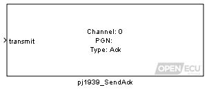
The send acknowledgement block can be used to acknowledge any PGN request (with either Ack, Nack, Access Denied or Busy responses).
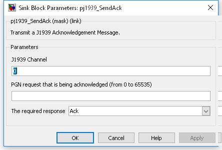
The logical J1939 channel on which to transmit. Must be a channel declared with a pj1939_ChannelConfiguration block.
Value type: Integer Calibratable: No The PGN request that is being acknowledged by this message.
The required response for this message: Ack, Nack, Access Denied or Busy.
Provide the facility to update the NTE status (as reported in J1939 message DM34).
EXT_DIAG (Extended diagnostics library). (See Section 1.3, “Licensed Features”.)

The platform requires information regarding the status of the engine operation in the NTE control areas, for given pollutants such as NOx and PM. This block provides the facility to update that information in order that a J1939 DM34 message (when requested) contains up-to-date data. Refer to J1939-73 FEB2010 section 5.7.34 for details of the various NTE areas.
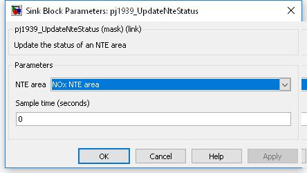
This block updates the platform data for the pj1939_dm34Transmit block.
Declares vehicle specific information (VIN, calibration ID, etc) as per service $09 of the J1979 diagnostic protocol.
EXT_DIAG (Extended diagnostics library). (See Section 1.3, “Licensed Features”.)
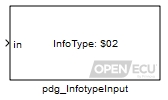
The InfoType designates the type of vehicle specific information that the application is supplying. This supplied vehicle specific information can be accessed using a diagnostic scan tool via J1979 service $09 by specifying the InfoType.
The InfoTypes $00, $20, $40,.. etc specify which InfoTypes an application supports. The underlying platform code implements the supported InfoType message. Placing the pdg_InfotypeInput block with an appropriate Infotype selected in the application model will cause the corresponding bitfield to be set in the supported InfoTypes message.
Application supplied data which is to be accessed via service 0x09 by a diagnostic scan tool.
Note this inport accepts inputs from multidimensional data types, such as a simulink Mux, simulink constant block whose constant value is a vector (specified in the data dictionary), etc.
Note the length of the supplied data must match that defined in the J1979 standard.
Value type: Integer Indicates the availablity of the application data. False indicates the data is available. When true, a J1979 request for the data will result in the negative response code $78 (requestCorrectlyReceived-ResponsePending) followed by a negative response code $78 message at 4.5s intervals until pending transistions to false where upon the supplied infotype data is sent.
Currently this is only required by Infotype 0x06 (CVN).
Value type: Boolean
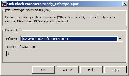
A drop down to select the service 0x09 InfoType.
- $02
Vehicle Identification Number.
- $04
Calibration Identifications
Note the number of data items (NODI) is currently limited to 1 for this InfoType
- $06
Calibration Verification Number (CVN)
- $0A
ECUNAME
- $0B
In-use Performance Tracking
This infotype is automatically generated by the platform software using the data processed by the Diagnostic Monitor Entities (see ppr_DiagnosticMonitorEntity for more details). Any value passed here will be ignored.
- $0D
Engine Serial Number
- $0F
Exhaust Regulation Or Type Approval Number
Value type: List Calibratable: No
Define a Diagnostic Monitor Entity.
EXT_DIAG (Extended diagnostics library). (See Section 1.3, “Licensed Features”.)
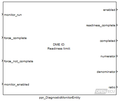
A Diagnostic Monitor Entity (DME) is a group of Diagnostic Test Entities (DTEs) and is represented by an ISO-15765 Monitor Identifier (OBDMID), a monitor group (which is used for reporting In-Use Performance Tracking over ISO-15765 protocol) and/or by a J1939 Suspect Parameter Number (which is used for reporting performance tracking over J1939 protocol). Examples of a DME monitor group are:-
NMHC converting catalyst
NOx converting catalyst
Catalyst
Exhaust gas sensor
Evaporative system
EGR and VVT system
Secondary air system
PM filter
Boost pressure control system
NOx adsorber
Fuel system
Secondary oxygen sensor
The platform holds information for each DME, consisting of monitor readiness status as well as monitor enable and monitor completion status. The monitor readiness status is a term used in OBD that refers to a vehicle's readiness for I/M inspection. For monitors that are non-continuous and have an emissions threshold, a readiness status indicator is stored to indicate whether or not that particular monitor has run enough times to make a diagnostic decision. The monitor enable status for the current driving cycle indicates when a monitor is not disabled in a manner such that there is no way for the driver to operate the vehicle for the remainder of the driving cycle and make the monitor run. The monitor completion status indicates if all monitoring conditions required for the particular monitor have been tested and a result has been obtained.
Set to 1 if the monitor has run, set to zero otherwise. This is used by the the platform to determine the monitor completion and readiness status. The platform increments the number of times a monitor has been run on each 0 to 1 transition of this inport, provided that inport monitor_enabled is set to 1 and force_complete and force_not_complete are both set to 0.
Range: 0 or 1
Value type: Boolean Calibratable: No Set to 1 to force the monitor readiness status to complete, independent of the number of times the monitor has been run. Set to 0 otherwise. The block responds on the rising edge of this inport.
Range: 0 or 1
Value type: Boolean Calibratable: No Set to 1 to force the monitor readiness status to incomplete, independent of the number of times the monitor has been run. Set to 0 otherwise. The block responds on the rising edge of this inport.
Range: 0 or 1
Value type: Boolean Calibratable: No Set to 1 to indicate the monitor is enabled, 0 otherwise.
Range: 0 or 1
Value type: Boolean Calibratable: No
Set to 1 if the DME is enabled, set to 0 otherwise.
Range: 0 or 1
Value type: Boolean Set to 1 if this DME's run count is greater than or equal to its Readiness count limit parameter, set to 0 otherwise.
Range: 0 or 1
Value type: Boolean Set to 1 if all monitoring conditions required for this DME have been tested and a result has been obtained, set to 0 otherwise.
Range: 0 or 1
Value type: Boolean If there is only one DTE for this monitor then the numerator will be set to that DTE's specific numerator. If there is more than one DTE, then the value of this outport will be the specific numerator corresponding to the lowest ratio found in the set of DTEs for this monitor.
Range: [0, 65535]
Value type: Integer If there is only one DTE for this monitor then the denominator will be set to that DTE's specific denominator. If there is more than one DTE, then the value of this outport will be the specific denominator corresponding to the lowest ratio found in the set of DTEs for this monitor.
Range: [0, 65535]
Value type: Integer If there is only one DTE for this monitor then the ratio will be set to that DTE's specific ratio. If there is more than one DTE, then the value of this outport will be the lowest ratio found in the set of DTEs for this monitor.
Range: [0.0, 7.99527]
Value type: Real
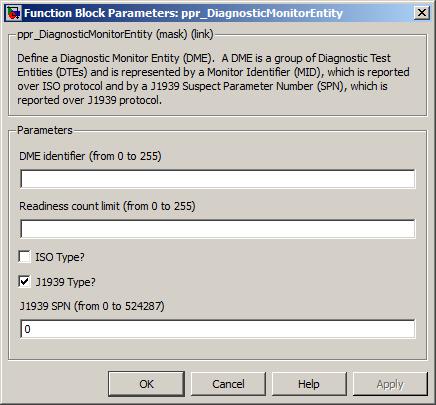
The unique identifier for this DME.
Range: [0, 255]
Value type: Integer The minimum number of times the monitor must be run before the monitor readiness status is set to complete.
Range: [0, 524287]
Value type: Integer Calibratable: No If this box is checked then the parameters pertaining to ISO specific DMEs are available. Note that a DME can be ISO type, J1939 type or both.
Range: 0 or 1
Value type: Boolean Calibratable: No The ISO-15765 monitor identifier (OBDMID - see J1979 spec dated Sept 2010 appendix D). It is used for reporting over ISO-15765 diagnostics in response to service $06. Only available if the ISO Type? option is checked.
Range: [0, 255]
Value type: Integer Calibratable: No A drop down to specify the ISO-15765 monitor group as described in J1979 spec dated Sept 2010 appendix G. It is used for reporting performance ratio data over ISO-15765 diagnostics, in response to service $09. Only available if the ISO Type? option is checked.
Value type: List If this box is checked then the parameters pertaining to J1939 specific DMEs are available. Note that a DME can be ISO type, J1939 type or both.
Range: 0 or 1
The value of the J1939 SPN for this DME. Only available if the J1939 Type? option is checked.
Range: [0, 524287]
Value type: Integer Calibratable: No
Define a Diagnostic Test Entity and the inputs which operate on it.
EXT_DIAG (Extended diagnostics library). (See Section 1.3, “Licensed Features”.)
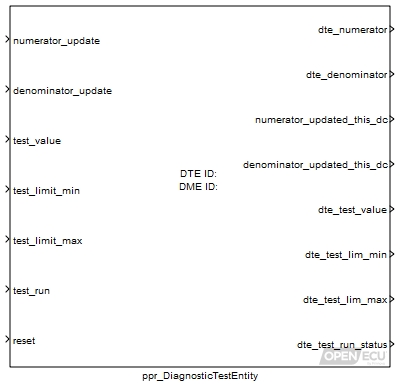
A DTE is a specific test for some vehicle component for which test results are recorded. It is represented by an ISO-15765 Test Identifier (ISO-TID), which is reported over ISO-15765 protocol and/or by a J1939 Test Identifier (J1939-TID), which is reported over J1939 protocol. The platform holds information for each DTE, consisting of a numerator (a measure of the number of times a vehicle has been operated such that all monitoring conditions necessary for a specific test (DTE) to detect a malfunction have been encountered) and a denominator (a measure of the number of times a vehicle has been operated). These are used to implement algorithms in the platform to individually track and report a minimum acceptable In-Use Performance Ratio (IUPR). The platform keeps track of whether the test value for the DTE has been updated at least once in the current drive cycle and holds test value and min and max limits for the DTE.
Set to 1 if the numerator for this DTE is to be updated, set to zero otherwise. The block responds to a rising edge on this inport. This is used by the block to increment the specific numerator for the DTE. Note that the DTE specific numerator will be incremented only once per drive cycle. Therefore, it is important that this inport is returned to level 0 before a new drive cycle event, if a numerator update is not required. The signal passed to this inport should be connected to all DTEs which contain the same Monitor identifier in order that the specific numerator is updated simultaneously for all those DTEs.
Range: 0 or 1
Value type: Boolean Calibratable: No Set to 1 if the denominator for this DTE is to be updated, set to zero otherwise. The block responds to a rising edge on this inport. This is used by the block to increment the specific denominator for the DTE. The user should set this inport to 1 only when every monitoring condition necessary for the monitor of the specific component to detect a malfunction and store a pending fault code has been satisfied. Note that the DTE specific denominator will be incremented only once per drive cycle. Therefore, it is important that this inport is returned to level 0 before a new drive cycle event, if a denominator update is not required. The signal passed to this inport should be connected to all DTEs which contain the same Monitor identifier in order that the specific denominator is updated simultaneously for all those DTEs.
Range: 0 or 1
Value type: Boolean Calibratable: No The test value collected during the test.
Range: [0, 65535]
Value type: Integer Calibratable: No The threshold which the test value must be above in order to pass the test.
Range: [0, 65535]
Value type: Integer Calibratable: No The threshold which the test value must be below in order to pass the test.
Range: [0, 65535]
Value type: Integer Calibratable: No Sets whether the test has been run at this time step.
When this input is 1, the block sets the test value and min and max limits for the DTE to the values on inports test_value, test_limit_min and test_limit_max respectively. When this input is 0, the stored test value and min and max limits are held unchanged. Note that this input is level-triggered and not edge-triggered. This is required so that results for continuously-monitored tests such as range checks on sensors may be updated at every step.
Range: 0 or 1
Value type: Boolean Calibratable: No Sets whether the test is to be reset at this time step.
Set to 1 to cause the block to reset the test value, test min and test max for this DTE to initial values of 0 and its test run status to 'test not run'. Set to 0, otherwise. Note that this input is level-triggered and not edge-triggered. This is required so that test results may be repeatedly reset if necessary. Note also that test_run takes precedence over this input.
Range: 0 or 1
Value type: Boolean Calibratable: No
The specific numerator for this DTE. Used internally for calculation of the DME's In-Use performance ratio which this DTE belongs to.
Range: [0, 65535]
Value type: Integer The specific denominator for this DTE. Used internally for calculation of the DME's In-Use performance ratio which this DTE belongs to.
Range: [0, 65535]
Value type: Integer Set to 1 if the specific numerator for this DTE has been updated this drive cycle, set to 0 otherwise.
Range: 0 or 1
Value type: Boolean Calibratable: No Set to 1 if the specific denominator for this DTE has been updated this drive cycle, set to 0 otherwise.
Range: 0 or 1
Value type: Boolean The test value that the platform holds for this DTE.
Range: [0, 65535]
Value type: Integer The test minimum threshold that the platform holds for this DTE.
Range: [0, 65535]
Value type: Integer The test maximum threshold that the platform holds for this DTE.
Range: [0, 65535]
Value type: Integer The test run status that the platform holds for this DTE. A value of 0 indicates that the test has never run. A value of 1 indicates that a test has run on this drive cycle. A value of 2 indicates that a test has run but not on this drive cycle.
Range: [0, 2]
Value type: Integer Calibratable: No
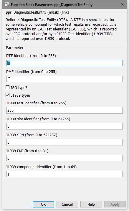
The unique identifier for this DTE.
Range: [0, 255]
Value type: Integer Calibratable: No The identity of the DME that this DTE belongs to. For example, an Exhaust gas sensor monitor will have a subset of DTEs. This DTE needs to have a matching DME identifier parameter with its parent DME.
Range: [0, 255]
Value type: List If this box is checked then the parameters pertaining to ISO specific DTEs are available. Note that a DTE can be ISO type, J1939 type or both.
Range: 0 or 1
Value type: Boolean Calibratable: No The ISO-15765 monitor identifier (OBDMID - see J1979 spec dated Sept 2010 appendix D) that this DTE belongs to. It is used for reporting over ISO-15765 diagnostics in response to service $06. Only available if the ISO Type? option is checked.
Range: [0, 255]
Value type: Integer Calibratable: No This identifier is used to reference the scaling and unit to be used by the external test equipment in order to calculate and display the test values (results), Minimum Test Limit, and the Maximum for the DTE. Only available if the ISO Type? option is checked.
Range: [0, 255]
Value type: Integer Calibratable: No The ISO specific test identifier (TID). Only available if the ISO Type? option is checked.
Range: [0, 255]
Value type: Integer Calibratable: No If this box is checked then the parameters pertaining to J1939 specific DTEs are available. Note that a DTE can be ISO type, J1939 type or both.
Range: 0 or 1
Value type: Boolean Calibratable: No The J1939 specific test identifier (TID). See J1939-73 Sept 2010 section 5.7.7.1 for details. Only available if the J1939 Type? option is checked.
Range: [0, 255]
Value type: Integer Calibratable: No This is the scaling, limit, offset, and transfer function for the DTE. Only available if the J1939 Type? option is checked.
Range: [0, 64255]
Value type: Integer Calibratable: No This is the SPN number associated with the DTE. Only available if the J1939 Type? option is checked.
Range: [0, 524287]
Value type: Integer Calibratable: No This is the FMI number associate with the DTE. See J1939-73 Sept 2010 Appendix A. Only available if the J1939 Type? option is checked.
Range: [0, 31]
Value type: Integer Calibratable: No This identifies the non-continuously monitored component identifier. Component identifiers are used to distinguish DTEs that have the same J1939 slot identifier Only available if the J1939 Type? option is checked.
Range: [1, 64]
Value type: Integer Calibratable: No This is the bit position to set in a requested DM10 message response, to indicate test supported. Refer to J1939-73 FEB2010 section 5.7.10 for details. The assignment of a given test identifier (as provided in the J1939 test identifier parameter) to a given bit position is manufacturer specific. This parameter is optional and may be left blank, in which case the DM10 bit position will default to the value provided in the J1939 test identifier parameter, provided it lies in the range specified below. Only available if the J1939 Type? option is checked.
Range: [1, 64]
Value type: Integer Calibratable: No
Provide the means to update the In-use performance ratio general denominator.
EXT_DIAG (Extended diagnostics library). (See Section 1.3, “Licensed Features”.)

The general denominator is defined as a measure of the number of times a vehicle has been operated and is not specific to a Diagnostic Test Entity. The general denominator is incremented by one if inport update is set to 1. Otherwise, no increment is attempted.
Set to 1 if the general denominator is to be incremented, set to zero otherwise. Note that the platform's general denominator will be incremented only once per drive cycle. Therefore, it is important that this inport is set to 0 before a new drive cycle event occurs, if a general denominator update is not required.
Range: 0 or 1
Value type: Boolean
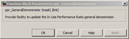
Provide the means to update the In-use performance ratio ignition cycle counter.
EXT_DIAG (Extended diagnostics library). (See Section 1.3, “Licensed Features”.)
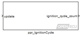
The ignition cycle counter is defined as a counter that indicates the number of ignition cycles a vehicle has experienced under certain engine speed conditions for a certain amount of time. The ignition cycle counter is incremented by one if inport update is set to 1. Otherwise, no increment is attempted. Note that the platform's ignition cycle counter will be incremented only once per ignition cycle.
Set to 1 if the ignition cycle counter is to be incremented, set to zero otherwise. Note that the platform's ignition cycle counter will be incremented only once per ignition cycle. Therefore, it is important that this inport is set to 0 before a new ignition cycle event occurs, if an ignition cycle counter update is not required.
Range: 0 or 1
Value type: Boolean Calibratable: No
Retain the In-use performance ratio data in non-volatile storage across power cycles.
EXT_DIAG (Extended diagnostics library). (See Section 1.3, “Licensed Features”.)
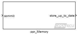
The ppr_Memory block stores the In-use performance ratio data in non-volatile memory. Storage consists of DME and DTE data plus the ignition cycle counter and general denominator. On start-up, the block attempts to retrieve the data prior to running the model. While the model is running, the time at which the data is stored back to non-volatile memory is determined by the model itself.
Failure to retrieve the data on start-up causes the data to be reverted to the default start-up conditions.
The target non-volatile memory may be provided in two ways: either through storage that requires an external power source when the ECU is powered down (battery backed RAM storage), or not (Flash storage). In the case of IUPR data, only Flash storage is supported. See the technical specification for details on which storage type is supported by each target.
This block is used to write the In-use performance ratio data to non-volatile store. When the inport commit is set to 1, the block pauses execution of the model, stores the IUPR data in non-volatile memory, then continues execution of the model.
Note
This block suspends the scheduler for a period of time. When storing the information, the worst case Flash erase time given worst case environmental conditions, can be around 1.8 seconds.
Old IUPR data is reused so long as it has the expected total data size and was written by an application with the same user-specified version number. Otherwise the values revert to defaults.
To ensure the IUPR data is up to date before shutting down the ECU, the store_up_to_date outport provides an indication of whether the storage to Flash was successful or not. If not, shutdown of the module can be prevented (if conditions are appropriate), and the store updated (by setting the commit inport to 1).
Provide a count of the total number of monitors (DMEs) that are enabled and have a readiness status of not complete.
EXT_DIAG (Extended diagnostics library). (See Section 1.3, “Licensed Features”.)
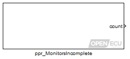
The count of the number of DMEs that are enabled and have a status of readiness not complete is calculated and presented on the count outport.
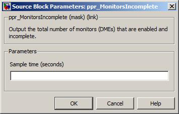
For each ECU, there is a technical specification which provides an overview of the electronics and components of the ECU, including a list of connectors, pin outs, pin capabilities, flash codes, and so on. These technical specifications are available from the Windows Start button and from the following links.
-
Generic ECUs
Available from Pi for general use.
M110-000 technical specification HTML PDF M220-000 technical specification HTML PDF M221-000 technical specification HTML PDF M250-000 technical specification HTML PDF M460-000 technical specification HTML PDF M461-000 technical specification HTML PDF M670-000 technical specification HTML PDF -
Customer ECUs
No Cutomer-specific ECUs are currently supported.
Further information about ECUs, including simplified I/O schematics and mechanical drawings, can be downloaded from the website (registration or purchase of ECU required) or requested through OpenECU technical support as described in Appendix K, Contact information.
This section provides a quick introduction to the tools that support OpenECU, both supplied by Pi Innovo and those by other companies. The section is intended to be a first step with the tools when used with OpenECU.
For tools that are supplied by other companies, additional details about how to use the tools can be found in their respective manuals. Pi Innovo will not provide technical support in the use of these tools.
The sections on the calibration tools (Section B.3, “ATI Vision”, Section B.5, “Vector CANape”,
Section B.4, “ETAS INCA”) and on a free programming tool called FreeCCP
(Section B.6, “FreeCCP”) assume that the step1 example application
(see Chapter 3, Quick start for details) has been built using the default CCP
settings (Table 6.3, “CCP defaults”) and that the user is familiar with
the installation of the calibration tool.
Pi Innovo's PiSnoop tool has many functions that are useful in typical OpenECU developments. It offers a cost-effective alternative to traditional calibration tools, but its emphasis is more on software development than calibration. Therefore it presents an interface that is part way to a debugger in terms of watch and memory windows, but typically interacts with the ECU via CCP, just like a calibration tool.
A demo version of PiSnoop is available from our website) in which all features may be tried out, but with some limitations on the number or duration of operations. This provides a route to getting up and running right away with OpenECU.
PiSnoop is under continual development, so this manual does not attempt to document how to use it with OpenECU in detail as is done for the other tools below. Instead, see the online help that is included in the PiSnoop installation (including the specific OpenECU application note) for up-to-date guidance. In brief however, capabilities include:
Works with any Vector, Kvaser or PEAK-System (PCAN) CAN interface on Windows XP or higher.
Loads symbols (parameter names, addresses, types and descriptions) from ASAP2 (.a2l) files...
... but can also load symbols from the linker output (.elf) files, giving access to all static C language objects present including arrays, structure elements, pointers and bitfields, without needing data dictionary entries. In Simulink builds, this means Real-Time Workshop structures such as
rtDWorkandrtBcan be explored, making "hidden" block-related values, present in the autocode, available for debug purposes.ECU memory access and flash reprogramming via CCP, with seed-key security support and fast DAQ data-logging, which tolerates ECU power cycling.
Reloading symbols and/or reprogramming the ECU after rebuilding is a single-click operation.
Calibration parameter value changes can be uploaded by name to a file, to use for download or flash reprogramming with a different build later.
Watch, map lookup and raw memory windows to view and edit ECU memory or offline file images.
CAN traffic generation and monitoring/logging with .dbc file support for named messages and signals.
ISO 15765-2 (UDS/Keyword Protocol/J1979) and J1939 diagnostic messaging windows.
UDS/Keyword Protocol can be used as an alternative memory access and flash reprogramming protocol, with seed-key security support.
ASAP3 support is provided to enable test automation.
Extensible through plug-in architecture supporting new protocols, hardware interfaces and custom windows.
This shows how calibration parameters and RAM variables can be accessed and logged together in debugger-style watch windows. Parameters can be loaded from ASAP2 (.a2l) and linker (.elf) files simultaneously. Structures, pointers, bitfields and arrays can be explored:
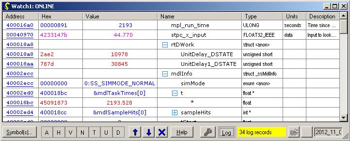
Debugger-style memory windows can be used to view and edit memory contents. Known symbols loaded from .a2l or .elf files are highlighted when the mouse pointer is placed over their locations:
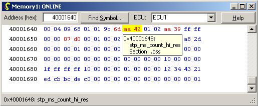
Further windows are integrated for CAN and diagnostic functions. For example, arbitrary CAN traffic can be generated by hand or using a .dbc file:
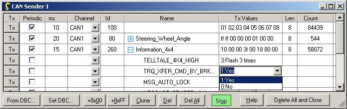
Similarly, CAN traffic can be monitored and logged:
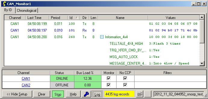
ATI Vision by Accurate Technologies is a calibration tool that can communicate to a CCP compliant device. It provides facilities for calibration, data logging and display and can be used with OpenECU.
The following instructions assume the user is using a supported version. These instructions were transcribed against a supported version but it may be that these instructions match other versions of the tool.
They also assume that an ATI Vision Hub is used. If another communications device is used, the user will need to deviate from these instructions.
Install ATI vision, the installer may reboot your machine. Once windows is restarted, it will detect new USB hardware (assuming the hub is plugged in: if not, plug it in).
Ask windows to install the USB hardware software from the "device software" directory located where you just installed ATI vision, e.g., c:\program files\Accurate Technologies\ati vision\device software.
Start Vision and you will be presented with a window similar to the following:
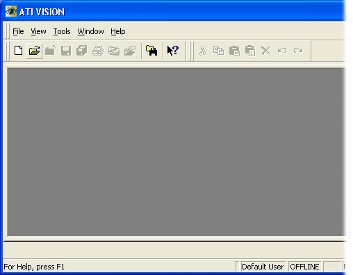
Next, you must create a project to details how ATI Vision will communicate with the OpenECU device.
Create a new project using the menu option File->New, then select Project.
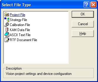
and save it somewhere on your hard-disk (here, it has been saved using the name "example_project").
Next, add a device by right clicking on the Computer item and selecting "Add Device..."
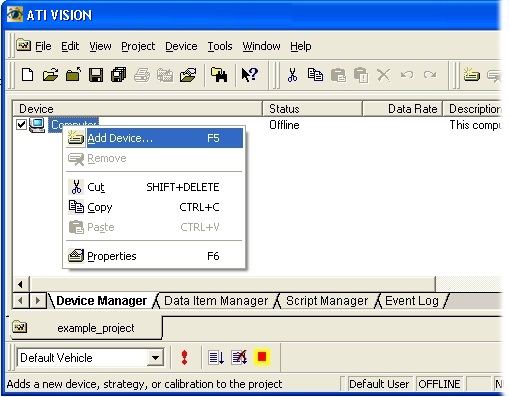
Select USB port and in the subsequent dialog, accept all the defaults and select OK.
Next, add a device by right clicking on the USB item and selecting "Add Device..."
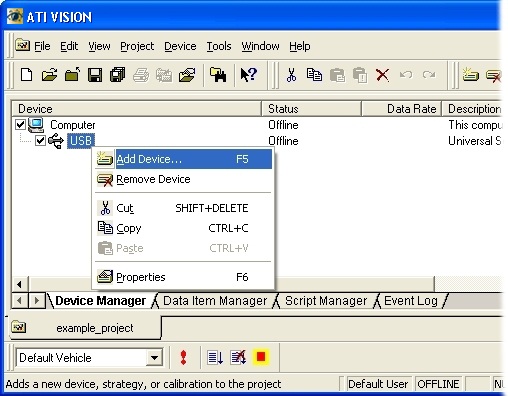
Select VISION Network Hub in the subsequent dialog and select OK.
Accept the default hub name and in the subsequent dialog properties defaults by selecting OK.
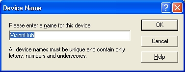
Next, add another device by right clicking on the VisionHub item and selecting "Add Device..."
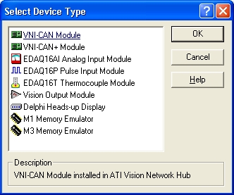
Select a VNI CAN device type, accept the default name and in the subsequent dialog, accept the defaults by selecting OK.
Next, add another device by right clicking on the VNICAN item and selecting "Add Device..."
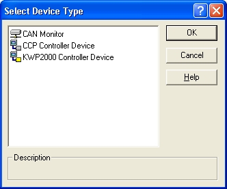
Select the CCP Controller Device, accept the default name and in the subsequent dialog, accept the defaults by selecting OK. This has told the Vision tool that you will be communicating to a CCP compatible device over CAN via the Vision Hub connected to the PC via a USB cable.
Next, you must create a strategy file to hold both the calibration data and program data. Select File->New, then Strategy File.
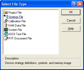
The main Vision window will change and you will be presented with the import wizard. Select the ASAP2 description file item.
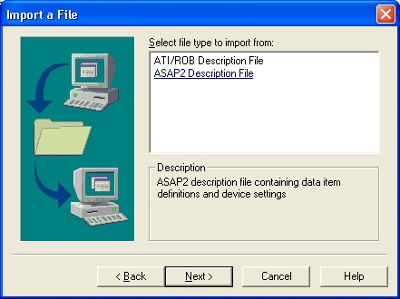
For the
step1example, select thestep1_tool_vision.a2lfile from the location where you built it (note that the following diagrams show an older version of the step1 application calledstep1_r12_g800).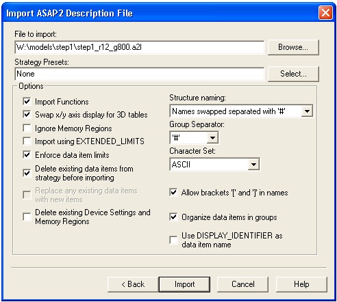
It is important to keep the "Strategy Presets" text box clear and to tick the "Delete existing data items from before importing" check-box. This ensures that the memory and CCP settings are taken from the ASAP2 file and that subsequent imports of the same strategy will clear out previous ASAP entries before loading the latest.
Click Import to read in the ASAP2 file, then click on the More button.
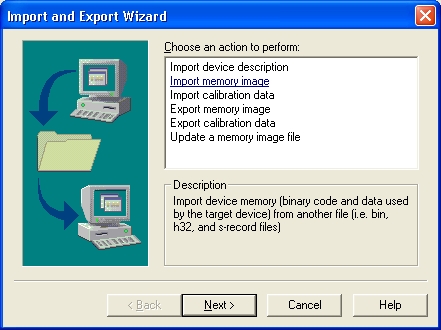
Select import memory image, then select Motorola S-record File, then browse and select the
step1_image_small.s37file from the place where you built it.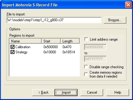
Select Import, then Finish. The Wizard dialog box now closes.
Note
You must now save this strategy (menu option File->Save) and change back to the project file by clicking on the "example_project" tab at the bottom of the Vision window.
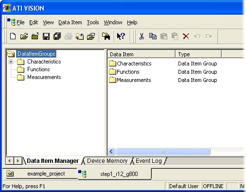
The following instructions assume the user is using a supported version of ATI Vision. These instructions were transcribed against a supported version but it may be that these instructions match other versions of the tool.
They also assume that an ATI Vision Hub is used. If another communications device is used, the user will need to deviate from these instructions.
Before building an application, select the Generate ATI Vision Strategy file RTW option (see Section 4.3.4, “Configuration options” for more details about how to do this). Alternatively, follow the instructions for creating an ATI Vision strategy described in Section B.3.1, “Creating a new project and strategy in ATI Vision”.
Add this strategy to the tree list by right clicking on the PCM item and selecting "Add Strategy...", browse to the location where you saved the strategy file and select it.
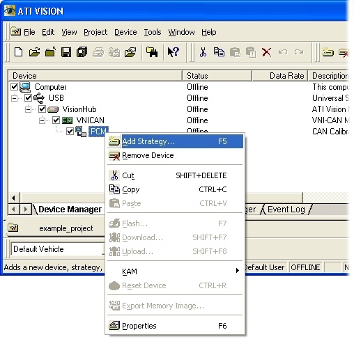
This will add two items to the tree view, one for the strategy and one for the calibration data immediately below it.
If CCP seed/key security is to be used, copy the relevant DLL(s) into the same location as the strategy file.
To try out the connection, go online by selecting the menu option Project->Online.
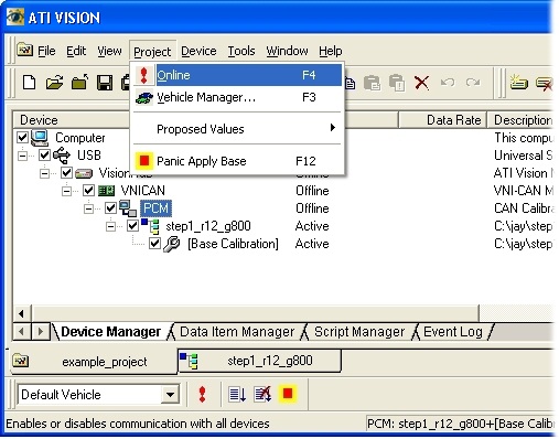
The tree view will change to show that each of the devices previously added are communicating correctly:
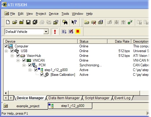
and brings up a dialog box:
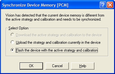
If any of the devices show a yellow or red mark, then there is a physical disconnection or CCP communications error (e.g., different settings for CCP in the OpenECU device and the application). The dialog box will not pop-up and you will not be able to Flash the device. Go back and check that each of the settings corresponds to physical devices and CCP settings, check that CAN is connected to the correct pins and try again.
To program the OpenECU device with the strategy, select Flash then OK. This brings up a dialog box which shows which memory regions on the OpenECU device to program. Select Start to program the device.
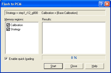
Note
In order to reprogram or Flash the OpenECU device, the OpenECU device must be in reprogramming mode. For details on how to enter reprogramming mode refer to Section 4.5, “Programming an ECU”
Once programmed, the FEPS must be disconnected (if used) and the OpenECU device power cycled. This reboots the OpenECU and starts to run the application.
You can now view ASAP2 entries by creating a screen and adding the application signals and calibrations you wish to see. Select File->New, then Screen File. The main window will change. Right click on the background and select "Add Control".
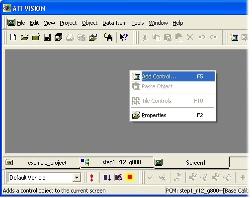
For now, we will only look at scalar values by selecting Data List items, but 1-d and 2-d maps are supported, as well as recorders etc..
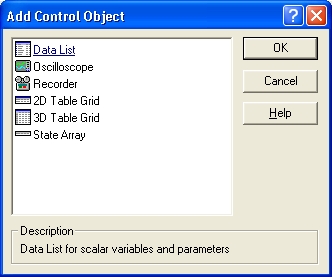
Select Data List and you will be presented with a dialog box which lists the ASAP2 entries.
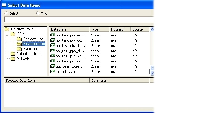
Double click on
stp_ect_stateand then select OK. You will be presented with the current value ofstp_ect_statein real-time.
At this point, you have managed to connect ATI Vision to OpenECU,
download the step1 application and view one application signal in
real-time. Please refer to the ATI Vision user manual for more details
about how to use ATI Vision.
When connecting to a single OpenECU for the first time, the tool and OpenECU settings will probably use the default CCP settings (as described in Table 6.3, “CCP defaults”). The example which follows assumes the default CCP settings.
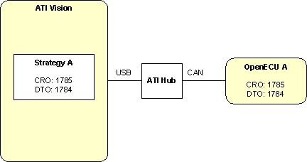
The above diagram shows ATI Vision with a single strategy using the default CCP settings. A similarly configured OpenECU is connected to ATI Vision via the CAN bus to the Vision Hub, and from the Hub to the PC via a USB cable. Your setup may vary depending on what equipment you have (for instance, you may have two ATI Hubs but the overall concept of configuring the additional OpenECU's remains).
When a second OpenECU is first required, a second application will be built into a second strategy which must use different CCP settings from the first strategy. The tool settings may follow the example default settings for two OpenECUs.
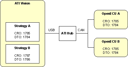
The diagram shows ATI Vision with two strategies: strategy A using the default CCP settings (as in the single OpenECU example above); strategy B using different CCP settings. The CCP settings distinguish between the two OpenECUs. Two OpenECUs are connected to the Hub allowing ATI Vision to communicate with both.
As this is the first time the second OpenECU has been connected to the CAN bus, it uses the default CCP settings. When the user selects strategy B in Vision, Vision uses the strategy B CCP CAN identifiers but there is no OpenECU with matching CCP settings. Without any response Vision shows the OpenECU for strategy B as offline.
Follow this procedure to program OpenECU B with strategy B for the first time:
Disconnect OpenECU A from the CAN bus. This prevents OpenECU A from interfering with communications to OpenECU B.
Right click on strategy B and select Open File. The screen will change.
Select File -> Properties and change to the Device Settings tab in the new dialog.
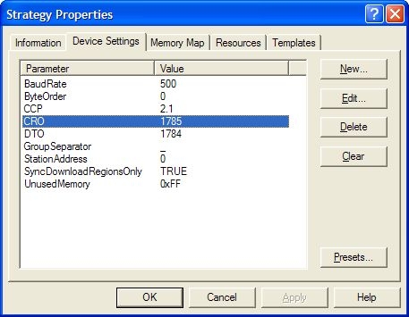
Change the CRO CAN identifier to 1785 and the DTO CAN identifier to 1784, then select File -> Save.
Change back to the Project tab (so you can see both strategy A and strategy B), right click on strategy B and select Reload File. This brings the CRO and DTO changes into strategy B.
Your setup is now configured as:
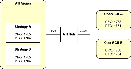
If strategy B is selected, ATI Vision will show OpenECU B as online.
Reprogram OpenECU B with strategy B (see Section B.3, “ATI Vision” and Section 4.5, “Programming an ECU” for more).
Once reprogrammed, power cycle OpenECU B. ATI Vision will show OpenECU B as offline.
Right click on strategy B and select Open File. Select File -> Properties, change to the Device Settings tab in the new dialog, change the CRO CAN identifier to 1787 and the DTO CAN identifier to 1786, then select File -> Save.
Change back to the Project tab (so you can see both strategy A and strategy B), right click on strategy B and select Reload File.
Your setup is now configured as:
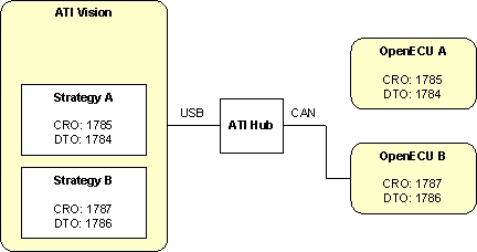
Reconnect OpenECU A to the CAN bus. Select strategy A to communicate with OpenECU A, or select strategy B to communicate with OpenECU B.
Note
The above procedure is equally applicable when reprogramming a single OpenECU to new CCP settings. Ensure there is only one OpenECU connected to the CAN bus, build the application with the new CCP settings, import into Vision, adjust the CCP settings in Vision to that of the connected OpenECU, reprogram the OpenECU and reset it, then adjust the CCP settings in Vision to that of the application.
Some manufacturers may enable CCP seed/key security for certain CCP operations, particularly in software which is released to production. Configuring this in the application is discussed in Section 6.1.21, “CCP seed/key security (pcp_CCPSecurity)”.
CCP seed/key security requires that a Win32 DLL is built containing a function which will generate a key value from a seed value supplied by the ECU. The name and function prototype are specified in the ASAP1A and ASAP2 standards to be
BOOL SEEDKEYAPI ASAP1A_CCP_ComputeKeyFromSeed(BYTE           *Seed,
                                              unsigned short  SizeSeed,
                                              BYTE           *Key,
                                              unsigned short  MaxSizeKey,
                                              unsigned short *SizeKey);
// Seed: Pointer to seed data
// SizeSeed:Size of seed data (length of ‚Seed‘)
// Key: Pointer, where DLL should insert the calculated key data.
// MaxSizeKey: Maximum size of ‚Key‘.
// SizeKey: Should be set from DLL corresponding to the number of data
// inserted to ‚Key‘ (at most ‚MaxSizeKey‘)
// Result: The value FALSE (= 0) indicates that the key could not be
// calculated from seed data (e.g. ‚MaxSizeKey‘ is too small).
// TRUE (!= 0) indicates success of key calculation.
Vision allows differently-named functions to be used, which may be convenient in cases such as supplying a single DLL containing multiple different seed/key algorithms for different strategies). Note though that this may make seed/key DLLs for Vision incompatibile with other calibrations tools which require a single function per DLL with a fixed name per the ASAP standard.
INCA by ETAS GmbH is a calibration tool that can communicate to a CCP compliant device. It provides facilities for calibration, data logging and display and can be used with OpenECU.
The following instructions assume the user is using version 5.1.2. These instructions were transcribed against this version but it may be that these instructions match other versions of the tool.
The instructions also assume that ES 580 CAN card is used. If another communications device is used, the user will need to deviate from these instructions.
Start INCA and you will be presented with a window similar to the following:
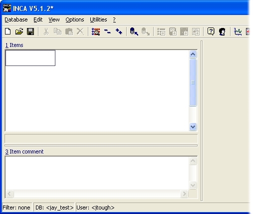
Select the menu option Database->New to create a new database. This database will contain the binary image of the built application and calibration and other items used to calibrate the OpenECU device.
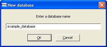
Type in a suitable name: the example here uses example_database and select OK.
Next, select the menu option Edit->Add->ECU Project (a2l) and browse to your built application, e.g.,
step1_tool_inca.a2l. The example shows an olderstep1_r12_g800application.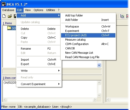
Once loaded, the INCA main window updates.
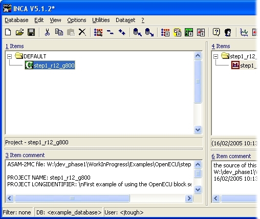
Next, select the menu option Edit->Add->Workspace and accept the default name, then select the menu option Project->Add Project/Dataset:

and a new dialog appears. Select the project you just added then OK. The main window will have updated to show the project in window 5.
Select the offline item in window 5, then select device->new device
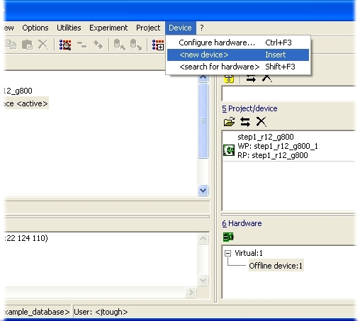
Select an appropriate CCP compatible device. In this example, the PC running INCA has a ES 580 CAN card attached, so the related CCP item is selected.
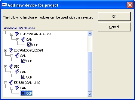
Next, double click on the workspace item in window 1. If there is an error in the CCP configuration or in the wiring to the OpenECU device, the INCA log window will show that INCA could not communicate with the OpenECU device. If this occurs, check the CCP settings and wiring.
If the memory pages dialog does not pop-up, the select the menu option Hardware->Manage memory pages
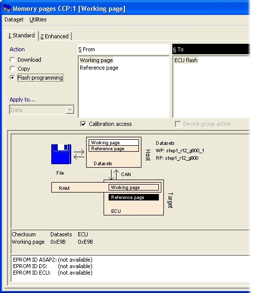
Select Flash programming, then do it. If this is the first time INCA has been used or if OpenECU was installed without the option to Patch INCA, you will be asked to browse to a ProF configuration file.
Note
The INCA tool makes a distinction between the base calibration (reference page) and a derived calibration (working page). Be sure to download the reference page to start with.
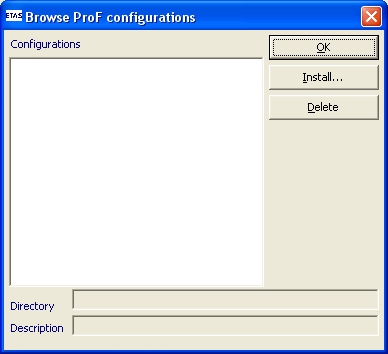
Select the "Install..." button and browse to the install location of OpenECU,
.../tools_integration/inca_profand select OK.This will have installed the INCA ProF configuration file for OpenECU. Select it then OK.
This brings up the ProF settings dialog.

Select Flash strategy and calibration (or Flash strategy, calibration and tunes if using Tunes in your application — the
step1application does not use Tunes), then OK.Note
In order to reprogram or Flash the OpenECU device, the OpenECU device must be in reprogramming mode. For details on how to enter reprogramming mode refer to Section 4.5, “Programming an ECU”.
This brings up the ProF control flow dialog box which shows the progress of programming the OpenECU device.
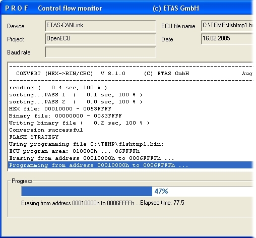
Press Close when it has finished and Close in the manage memory pages dialog.
Next, to view a measurable, select the menu option Variables->Select...
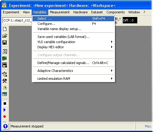
and from the dialog that pops up, select those signals or calibrations to view. Here, the
stp_ect_statesignal has been selected and will be updated every 100 milliseconds.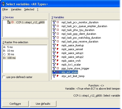
Select the Configure button, followed by the OK button on the next dialog.
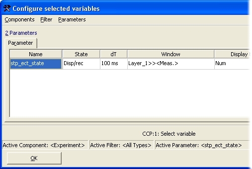
Finally, to display the data of the selected item in real-time, select the menu option Measurement->Start Visualisation. You will be presented with the current value of
stp_ect_statein real-time.
At this point, you have managed to connect ETAS INCA to OpenECU,
download the step1 application and view one application signal in
real-time. Please refer to the ETAS INCA user manual for more details
about how to use INCA.
CANape by Vector Informatik GmbH is a calibration tool that can communicate to a CCP compliant device. It provides facilities for calibration, data logging and display and can be used with OpenECU.
The following instructions are for version 8.0. Other versions may differ.
The instructions also assume that CANcaseXL is used. If another communications device is used, the user may need to deviate from these instructions.
Start CANape and you will be asked to accept a disclaimer. After this you will see the following:
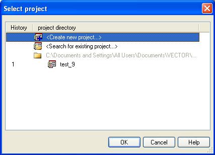
Select 'Create new project' and press 'OK'. You will then be asked for a project name. Enter a suitable name, click 'Next' and then browse to a suitable directory to save the project, click 'Next' and then 'Finish'. You should now see the following:

Select the menu option Device->New from database... and browse to where your model_name_canape.a2l file is located and select Open. If the device is connected correctly and configured with the appropriate baud rate then you should see no errors or warning. The a2l file contains the CAN configuration as set by the model. It also has the relevant information for the flash, cal and RAM locations. CANape will use these values with no further configuration input required from the user.
If CCP seed/key security is required for an operation, the DLL implementing the appropriate key-generation algorithm must be placed in the same directory as the CANape project. Note that CCP seed/key security is disabled by default in the model_name_canape.a2l file.
Having set up the project (and CCP security if required), select the menu option Flash->Download file to flash... and browse to your built application, e.g.,
step1_m460_image_small.hex. Depending on the size of the memory region to be flashed, it may be necessary to increase the flash clear timeout parameter in CANape.At the bottom left of the window the progress bar should be seen to advance until programming is complete.
Next, select the menu option Measurement->Measurement configuration... and the following window will appear:
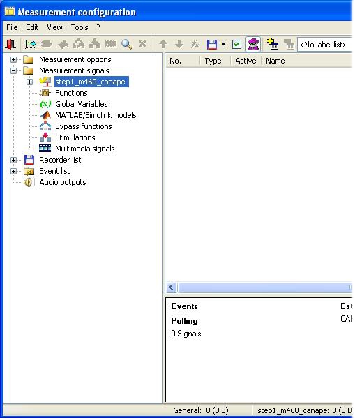
The Simulink model name should be visible in the left hand pane under 'Measurement signals'. Right click on the model name and select 'Insert signal' from the menu that appears. The Database selection window should then appear, listing all of the model signals and calibrateable values.
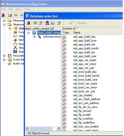
Double click on each signal of interest so that their text colour changes to blue. Close both windows and accept changes and you will return to the main window. Now select the menu option Display->Display windows->Numeric window, an empty numeric display will appear. Right click on this numeric display and select 'Insert measurement signal...' the following appears:
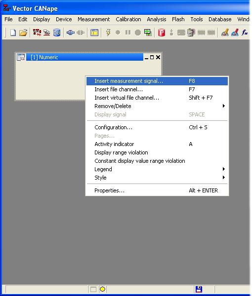
Next, right click and select 'Insert signal' on each parameter that you want to monitor in the numeric window
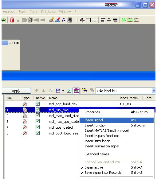
To access calibration values select the menu option Display->Calibration windows->Calibration window, then scroll down to find calibration parameters and select the ones that are required.
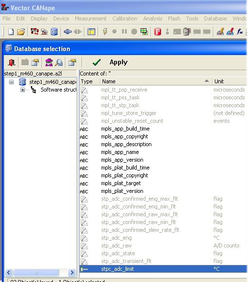
At this point, you have managed to connect Vector CANape to OpenECU,
downloaded the step1 application and viewed some signals in
real-time. Please refer to the Vector CANape user manual for more details
about how to use CANape.
Some manufacturers may enable CCP seed/key security for certain CCP operations, particularly in software which is released to production. Configuring this in the application is discussed in Section 6.1.21, “CCP seed/key security (pcp_CCPSecurity)”.
CCP seed/key security requires that a Win32 DLL is built containing a function which will generate a key value from a seed value supplied by the ECU. The name and function prototype are specified in the ASAP1A and ASAP2 standards to be
BOOL SEEDKEYAPI ASAP1A_CCP_ComputeKeyFromSeed (BYTE *Seed,
unsigned short SizeSeed,
BYTE *Key,
unsigned short MaxSizeKey,
unsigned short *SizeKey);
// Seed: Pointer to seed data
// SizeSeed:Size of seed data (length of ‚Seed‘)
// Key: Pointer, where DLL should insert the calculated key data.
// MaxSizeKey: Maximum size of ‚Key‘.
// SizeKey: Should be set from DLL corresponding to the number of data
// inserted to ‚Key‘ (at most ‚MaxSizeKey‘)
// Result: The value FALSE (= 0) indicates that the key could not be
// calculated from seed data (e.g. ‚MaxSizeKey‘ is too small).
// TRUE (!= 0) indicates success of key calculation.
Some calibration tools allow different function names to be used, but CANape does not. Each seed/key algorithm must therefore be provided in a separate DLL and referenced appropriately. Section 4.3.1.1 "CCP Parameters" of the CANape user manual specifies this in more detail.
FreeCCP is a command line tool which can program an OpenECU with a built application. It requires a Vector or Kvaser CAN card.
This tool is provided free and unsupported by Pi Innovo. Users are permitted to use this software for commercial and non-commercial purposes.
Note
On 64-bit Windows 7 PCs, FreeCCP does not currently work with Vector interfaces, but does with Kvaser interfaces.
Note
FreeCCP is now deprecated, and so may be removed from future releases of OpenECU. Please contact support if you would like a free trial of PiSnoop to get started with OpenECU, even if you intend to migrate to a third-party calibration tool. See also Section B.2, “PiSnoop”.
To program an OpenECU with a built application using a Kvaser CAN card, issue the following
at the command
line (if using MATLAB, use the oe_freeccp command instead):
oe_freeccp -kvaser -f <application_name>_image_small.s37
where <application_name> is replaced by the name of the application. For
instance, with the step1 application for the M670 target, the command to issue
would be:
oe_freeccp -kvaser -f step1_m670_image_small.s37
Note
The command can be run from either the Windows command line or MATLAB command
line. If running from the Windows command line, add the path to the freeccp
tool to the system PATH environment variable.
The tool supports using a variety of Kvaser CAN cards. To use this interface use the
-kvaser command line option.
oe_freeccp -kvaser -f <application_name>_image_small.s37
The tool supports using a variety of Vector CAN cards. The tool defaults to using a
CANcardX interface, but can connect to others using the following options:
-cancardxl or
-pci.
The options are added to the command for reprogramming, so as an extension to
programming an OpenECU device with the step1 application, choosing the AC2 PCI
option would be:
oe_freeccp -pci -f step1_image_small.s37
Without additional command line parameters, the tool uses the default CCP settings from (Table 6.3, “CCP defaults”. To make the tool use alternative CCP settings, use the following options:
-croid    <standard can identifier>
-dtoid    <standard can identifier>
-targetid <station address>
-b        <baud rate in kBps>
So for instance, if the CCP settings were:
| CCP option | Setting |
|---|---|
| CRO message identifier | 400 |
| DTO message identifier | 401 |
| Station address | 2 |
| CAN baud rate | 500 kBps |
then the command to issue to download the step1 application using
a Vector CAN card would be:
oe_freeccp -croid 400 -dtoid 401 -targetid 2 -b 500 -f step1_image_small.s37
CCP seed/key security is not supported by FreeCCP. FreeCCP cannot therefore carry out operations for which the currently-running application requires security to be unlocked. This may make it unsuitable for use with production-level software.
The tool supports a function to determine if it can communicate with an OpenECU device or not, rather than programming the device. This can be used to check the wiring between the OpenECU and CAN card.
To check the CCP connection using a Vector CAN card, issue the command:
oe_freeccp -check
This chapter gives an overview to some of the OpenECU Simulink examples provided with the developer software package.
Simulink provides a mechanism to integrate existing or custom C code with a model, usually with little change to the C code itself. It may be beneficial to mix Simulink and C code for a number of reasons. For instance:
when there is an existing body of C code which would take a significant amount of effort to re-create as a Simulink model;
when an existing algorithm written in C has been tested and proven to work correctly — the code is at a mature stage and re-creating the code in Simulink means additional testing is required;
when an algorithm written in C code might be more efficient and easier to understand than the equivalent created using Simulink blocks.
Existing or custom C code can be incorporated into a Simulink model using S-functions. S-functions can be written in MATLAB, C, C++, Ada, or Fortran and except for the MATLAB type function, the rest are compiled as a MEX-function using the MATLAB mex utility. An S-function can be used with Simulink Coder and the code generated by Simulink Coder for S-functions can be customized by writing a Target Language Compiler (TLC) file.
This section explains how to write and integrate a C type S-function into an OpenECU Simulink model (OpenECU does not support C++, Ada or Fortran S-functions, or non-inlined S-functions). S-functions with TLC files, are called inlined S-functions, while S-functions without TLC files are non-inlined. For OpenECU models, a TLC file is required, which improves the efficiency of code generation and helps reduce RAM usage.
Note
See “S-Functions and Code Generation” in MATLAB's help section for more information.
To create a S-function, begin by copying the files listed below from the directory:
[OpenECU install directory]\examples\simulink\two_pot_demo_w_sfunction\tpd\
to a data dictionary directory of your model directory:
[your model directory]\[data dictionary directory]
xx_code.hThis file defines the interface to the C source code.
xx_code_wrapper.cThis file tells MATLAB how to simulate the S-function block.
xx_code_wrapper.tlcThis file tells MATLAB how to generate code for the S-function block.
xx_code.cThis file implement's the user's algorithms as C source code.
rtwmakecfg.mThis file tells MATLAB where the C source code is located.
The xx part of the file name represents the core function of the S-function
and it's up to the user to choose an appropriate name. If multiple S-functions are created
then each function should have a unique set of files.
As the OpenECU model load scripts add each of the data dictionary directories to MATLAB's path, then by placing the files in a data dictionary directory MATLAB will be able to find the S-function and the hand-written C code is located.
Note
Some versions of MATLAB and OpenECU cannot correctly deal with paths that include spaces.
Make sure the path of the model directory doesn’t have any spaces (e.g. a good example is
C:\TestModel\drc\; a bad example is C:\Documents and
Settings\Test Model\drc\).
The xx_code.h, xx_code_wrapper.c, xx_code_wrapper.tlc and
xx_code.c files have step by step instructions embedded within the code.
Changes will be required to parts of the code following comments which look like:
/*
 *****************************************************************************
 * Step n:
 * ...
 ******************************************************************************
 */
The number n is the step number and each step is explained below. Other sections of the code are generic and do not need to be altered. Follow the steps below in sequence to create a S-function which implements custom C code.
Begin by editing the xx_code.h file:
Replace the literal
TPD_CODE_Hwith a name unique across all source files, to protect against double inclusion.Define the data types and assign names for the inports and outports of the S-function.
Note
These are the name that will be used to pass data from Simulink into the C code and from C code to Simulink via the inports and outports.
Edit the xx_code_wrapper.c file:
Define
S_FUNCTION_NAMEas the S-function wrapper name.Include the S-function C code file (i.e
xx_code.c).Define the number of arguments, inports and outports used in the S-function.
Note
In this example, the S-function does not use any input arguments, so the number of arguments is set to 0. For more information on how to use input arguments, please refer to the S-function block’s help section.
Define the properties of each inport used in the S-function.
Define the properties of each outport used in the S-function.
Get hold of storage locations of the data being sent from Simulink to the S-function via the inports.
Get hold of storage locations of the data that is going to be sent to Simulink from the S-function via the outports.
Note
The port numbers start from 0 and not 1. For more information on the property functions, search for the section named “Writing S-functions” or search using the property function name under MATLAB's help.
Pass the data received from Simulink via the inports to the C code.
Pass the data received from the C code to Simulink via the outports.
Edit the xx_code.c file.
Include the header file for the S-function.
Add the variables used in the S-function that need to be calibratable.
Note
The variable should have a four letter prefix with the fourth letter set to
c(e.g.mbec_maximum_engine_speed). See the variable naming requirements in section Section 5.2.5, “Naming rules”.
This is where the main algorithm is going to be located.
Edit the xx_code_wrapper.tlc file:
Update
%implementsdirective with the S-function wrapper name.Include the S-function C code header file (i.e
xx_code.h).Include the S-function C code file (i.e
xx_code.c).Pass the data received from Simulink via the inports to the C code.
Execute the C-code function.
Pass the data received from the C code to Simulink via the outports.
After making changes to the source code, do the following:
MEX Setup
Change MATLAB path to the data dictionary directory where the C files are.
Issue the command
mex –setupat MATLAB's command prompt and when prompted with the question: “Would you like mex to locate installed compilers [y]/n?”, enter
Y.Then choose the number associated with the desired compiler and when prompted with the question: “Are these correct?”, enter
Y.
Note
This step need to be done once and MATLAB will remember these settings each time it is opened.
Compile and Link Source Files
Change MATLAB path to the data dictionary directory where the C files are.
Issue the command
mex xx_code_wrapper.cat MATLAB's command prompt.
If there are no errors, MATLAB will compile and link the source files into a DLL file but won’t give any confirmation that the compilation was successful. The DLL file is used by Simulink to create the S-function block with an appropriate number of inports and outports, and to perform the C source code algorithms when simulating the model.
If there are errors, MATLAB will display and errors in the command window. Fix the errors and re-issue the previous command.
Note
These steps need to be done each time the S-function or algorithm C code is altered for the new changes to take effect.
Run the Model
Change MATLAB path to the model directory and open the model.
Insert an S-function block from the User-Defined Function.
Double-click on the block to open it. In the S-function Name field insert the name of the wrapper i.e
xx_code_wrapper.Click OK and then click update.
If there has been no problem with the previous steps, the inports and outports on the S-function block will appear. The block is now ready to be used when simulating or building the model.
If the source files were not compiled and linked into a DLL, the following error will be displayed “Error in S-function 'model directory/model name/S-function name': S-function 'xx_code_wrapper' does not exist”.
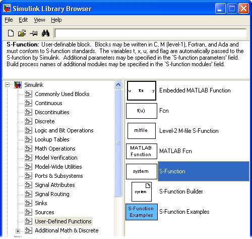
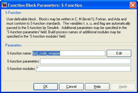
The S-function is now ready to be used when simulating or building the model. Each time the C
sources are modified, the S-function must be built manually by issing the
mex command. However, it is possible to build the S-function automatically
by adding a callback function to the S-function block. The advantage is that Simulink invokes
the callback before the model is simulated, updated or built, ensuring the S-function is up to
date regardless of whether the C sources have been altered or not. The disadvantage is that if
the C sources are large, there can be a noticable delay each time the model is updated,
simulated or built.
The S-function can be setup with a callback function as follows:
Right-click on the S-function block and choose Block Properties.
Then choose InitFcn and enter the following commands:
cd ddd
mex xx_code_wrapper.c
cd ..
where
dddis replaced with the name of the data dictionary directory.
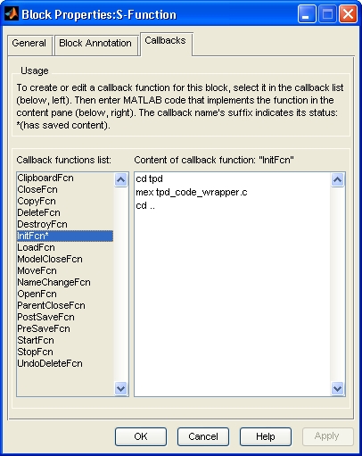
Some OpenECU targets support different configurations of the ECU's application, calibration and RAM memory sizes, allowing design trade offs to be made whilst developing the application. There are two broad classes of ECUs:
- Fleet ECUs
Lower-cost that developer ECUs due to the lack of run-time calibration support. These ECUs are intended to be used for fleet trials or production, and are not intended to be used for bench or dyno activities, especially those that require calibration support. Typically, fleet ECUs do not include external RAM.
- Developer ECUs
Higher-cost that fleet ECUs due to support for run-time calibration. These ECUs are intended to be used for development activities such as dyno cell calibration or HIL based testing. Typically, developer ECUs do include external RAM.
Some configurations support running identical software on fleet and developer units. An application can be built, run and calibrated on a developer ECU, then transfered to a fleet ECU of the same family and type as the developer unit, and run unmodified. An example of this would be memory configuration A for the M220, and memory configuration D for the M670. The same application, calibration and RAM memory sizes are available with and without run-time calibration support. An application built for M220 memory configuration A will run on both M220 developer and fleet units without modification.
M110
The following memory configurations are available.
Table D.1. Memory configurations supported
| Configuration | App size (KiB) | Cal size (KiB) | RAM size (KiB) | External RAM required? | Run-time calibration supported? |
|---|---|---|---|---|---|
| A [a] | 512 | 32 | 32 | N | Y |
| B | 512 | 48 | 16 | N | Y |
| C | 512 | 16 | 48 | N | Y |
| D | 512 | 256 | 64 | N | N |
[a] If an OpenECU target that supports memory configuration is loaded with an application in which no such configuration has been specified, then configuration A will be used as the default. | |||||
M220, M250, M460, M461
The following memory configurations are available.
Table D.2. Memory configurations supported
|
Configuration |
App size (KiB) |
Cal size (KiB) |
RAM size (KiB) |
External RAM required? |
Run-time
calibration supported? |
|---|---|---|---|---|---|
| A [a] | 512 | 256 | 64 | N | N |
| 512 | 256 | 64 | Y | Y | |
| B | 512 | 256 | 832 | Y | Y |
| C | 640 | 128 | 192 | Y | Y |
| D | 768 | 64 | 768 | Y | Y |
[a] If an OpenECU target that supports memory configuration is loaded with an application in which no such configuration has been specified, then configuration A will be used as the default. | |||||
Most of these configurations require the external RAM available with developer units. If an application using such a memory configuration is loaded onto an ECU with no external tab board RAM available, the ECU will entry reprogramming mode with a flash code of 1-1-7 (repeated resets).
M670
The following memory configurations are available.
Table D.3. Memory configurations supported
|
Configuration |
App size (KiB) |
Cal size (KiB) |
RAM size (KiB) |
External RAM required? |
Run-time
calibration supported? |
|---|---|---|---|---|---|
| A [a] | 3072 | 128 | 128 | N | Y |
| B | 3072 | 64 | 192 | N | Y |
| C | 3072 | 192 | 64 | N | Y |
| D | 3072 | 512 | 256 | N | N |
| 3072 | 512 | 256 | Y | Y | |
[a] If an OpenECU target that supports memory configuration is loaded with an application in which no such configuration has been specified, then configuration A will be used as the default. | |||||
Other targets
No other targets support memory configuration.
The OpenECU generation of ASAP2 files is against a sub-set of version 1.40 of the standard.
Warning
OpenECU does not adhere to the ASAP2 rule which governs the length of identifiers. OpenECU may generate identifiers with more than 32 characters.
The OpenECU implementation of CCP is against a sub-set of version 2.1 of the standard and supports the following commands:
Table F.1. Supported CCP commands
| CCP command | Command value | Optional | Notes |
|---|---|---|---|
| CONNECT | 1 | Reprogramming code prior to version 5.0.6 and 105.0.11 assumes a station address of zero or one. | |
| SET_MTA | 2 | Supports one MTA. Addresses must not be extended. | |
| DNLOAD | 3 | ||
| UPLOAD | 4 | ||
| START_STOP | 6 | ||
| DISCONNECT | 7 | Reprogramming code prior to version 5.0.6 and 105.0.11 assumes a station address of zero or one. | |
| START_STOP_ALL | 8 | yes | |
| SET_S_STATUS | 12 | yes | |
| GET_S_STATUS | 13 | yes | |
| BUILD_CKHSUM | 14 | yes | Implements the 16 bit CCITT CRC (shift register initially set to 0xFFFF, non-reflected form). |
| SHORT_UP | 15 | yes | Expects no address extension. Does not change MTA. |
| CLEAR_MEMORY | 16 | yes | |
| GET_SEED | 18 | yes | Not supported before platform version 1.8.6. |
| UNLOCK | 19 | yes | Not supported before platform version 1.8.6. |
| GET_DAQ_SIZE | 20 | Ignores any attempt to set the DAQ CAN message identifier to anything other than the DTO CAN message identifier. | |
| SET_DAQ_PTR | 21 | ||
| WRITE_DAQ | 22 | ||
| EXCHANGE_ID | 23 | Access to the ECU's type, manufacturing data, and if available, the application defined name. See Section F.1, “EXCHANGE_ID message handling” for details. | |
| PROGRAM | 24 | yes | If the length to program is specified as zero, reprogramming code will treat this as a special signal to indicate that programming has finished. |
| GET_CCP_VERSION | 27 | Returns 2.1. | |
| PROGRAM_6 | 34 | yes | |
| DNLOAD_6 | 35 | yes |
Some older versions of software (prior to platform version 1.6.0, or prior to RPRG version x.6.0) support a larger number of CCP commands. In addition to the commands above, these older versions also supported the following commands:
Table F.2. Supported CCP commands (in older versions of ECUs)
| CCP command | Command value | Optional | Notes |
|---|---|---|---|
| TEST | 5 | yes | Reprogramming code prior to version 5.0.6 and 105.0.11 assumes a station address of zero or one. |
| GET_ACTV_CAL_PG | 9 | yes | Only one page of calibration is supported. |
| SELECT_CAL_PAGE | 17 | yes | Only one calibration page is supported at a fixed address. |
| MOVE | 25 | yes | |
| DIAG_SERVICE | 32 | Replied to as "unavailable". | |
| ACTION_SERVICE | 33 | Replied to as "unavailable". |
All other commands are replied to as "unknown command".
The ASAP1b standard for CCP defines the EXCHANGE_ID message as follows:
Table F.3. Original EXCHANGE_ID message
| Position | Type | Description |
|---|---|---|
| 0 | byte | Command Code = EXCHANGE_ID 0x17 |
| 1 | byte | Command Counter = CTR |
| 2... | bytes | CCP master device ID information (optional and implementation specific) |
OpenECU will interpret the master device ID information to determine how to setup the Memory Transfer Address (MTA0) for later uploading.
Table F.4. Modified EXCHANGE_ID message
| Position | Type | Description |
|---|---|---|
| 0 | byte | Command Code = EXCHANGE_ID 0x17 |
| 1 | byte | Command Counter = CTR |
| 2..4 | bytes | Ignored |
| 5..6 | byte |
Manufacturing data key
See Table F.6, “EXCHANGE_ID manufacturing data key values and binary format” |
| 7 | bytes |
Selection
See Table F.5, “EXCHANGE_ID selection values” |
The message is processed by the ECU by inspecting the selection in position 7:
Table F.5. EXCHANGE_ID selection values
| Value | Description |
|---|---|
| 1 |
If the ECU contains manufacturing data and the manufacturing data key in position 5..6
is valid for the ECU, then set the MTA0 to the address of the manufacturing data in
binary format. Valid key values and the structure of the data is defined in
Table F.6, “EXCHANGE_ID manufacturing data key values and binary format”.
Otherwise, leave MTA0 unmodified and set an appropriate error code in the response message. Note that some older M220, M250, M460 and M461 variants do not contain manufacturing data. |
| 2 |
If running in application mode then set MTA0 to null terminated ASCII string defined
by the application
in the put_Identification block.
Otherwise, sets MTA0 as if the EXCHANGE_ID selection value were zero. |
| any other value | Set MTA0 to the address of a null terminated ASCII string of the ECU family. The string has the form “OpenECU-[name]”. For example, “OpenECU-M220”. |
Position 5 (MSB) and 6 (LSB) is interpreted as the manufacturing data identifier:
Table F.6. EXCHANGE_ID manufacturing data key values and binary format
| Position [a] | Description [b] |
|---|---|
| Key = 1, Serial number | |
| 0..3 | Serial number |
|
Key = 2, Date of manufacture
The date is composed as (shift) dd:mm:yyyy, where the shift identifies the team involved in the manufacturing process. | |
| 0 | The team shift at time of manufacture |
| 1 | The day of the month of manufacture, range [1, 31] |
| 2 | The month of manufacture, range [1, 12] |
| 3..4 | The year of manufacture, range [2010, ...] |
|
Key = 3, Engineering part number
The engineering part number matches the pattern: prefix letter engineering-part-number. For instance, the engineering part number assigned to the M250-000 is '01T068165', where '01' represents the prefix, 'T' represents the letter and '068165' represents the engineering part number. | |
| 0 | The part number prefix, range [0, 99] |
| 1 | The part number letter, represented in ASCII, range [A-Z] |
| 2..5 | The engineering part number, range [0, 999999] |
|
Key = 4, ECU mod and issue numbers
The issue level represents a specific design of PCB. Changes to the issue level may have an effect on the software version. The modification level represents what changes were performed to the PCB after manufacturing to correct issue level design mistakes. Changes to the modification level should not have an effect on the software version. | |
| 0 | The PCB issue level, range [0, 255] |
| 1 | The PCB modification level, range [0, 255] |
|
Key = 5, Factory part number
For instance, the factory part number could be '450FT1034', where '450' represents the part_num[0], 'F' represents the letter[0], 'T' represents the letter[1], and '1034' represents the part_num[1]. | |
| 0..1 | First number of identifier, range [0, 65535] |
| 2..3 | Second number of identifier, range [0, 65535] |
| 4..5 | Characters used to separate identifier numbers, represented in ASCII, range [A-Z] |
| Key = 6, Factory part number build type | |
| 0..1 | The factory part number build type, represented in ASCII, range [A-Z] |
[a] All data is arranged in MSB format. [b] Not all keys are available on all ECUs. | |
This section describes a troubleshooting procedure for when CCP communications can not be established:
This section explains the symptoms and the solution using examples of a system with an ATI Hub and ATI Vision. Specific issues with ATI products are not addressed in this document as are issues with other system configurations such as ATI's Kvaser and ETAS' INCA, although the overall symptoms and resolutions remain the same.
Note
This guide is provided to help diagnose issues when connecting OpenECU with ATI Vision, and is a reference only. Please direct technical support questions regarding ATI products, to ATI. Pi can supply support for Pi products only.
If at the end of following this guide, the OpenECU module will not communicate to ATI Vision, please get in touch with OpenECU technical support (see Appendix K, Contact information).
As a reference to the following troubleshooting guide, this diagram outlines the major interfaces to the ATI Hub. Please refer to the ATI Vision User Guide for further details.
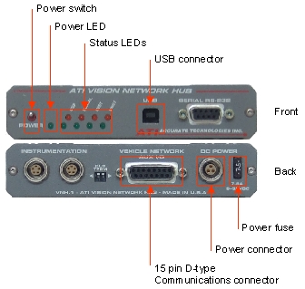
ATI Vision indicates that the Hub and its components are offline. No transmission data rate is shown as no data is communicated. In this case, ATI Vision shows red crosses against “VisionHub”, “VNICAN” and “PCM” while in online mode. The red crosses disappear when while in offline mode.
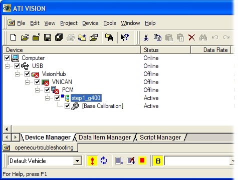
There are several potential reasons why there are no communications between the computer and the ATI Hub. Also see the Help instructions in ATI Vision's User Guide for further description of how to use the ATI Hub.
- Troubleshoot
Check that the “Power LED” on the ATI Hub is illuminated.
- Solution
Check that the “Power switch” is in the ON position (pointing upwards).
Check that the 12V DC is applied on the power connector at the back of the ATI Hub.
Check the fuse at the back of the ATI Hub is intact.
- Troubleshoot
Ensure ATI Hub is powered on (see Section G.2.2, “Possible causes”).
- Solution
Check that the USB cable between the ATI hub and the computer is connected properly.
Ensure that the correct USB driver is installed on the computer (contact ATI Technical Support for more details about the correct USB driver).
ATI Vision indicates that the PCM is offline. A transmission data rate is shown between the computer USB and the Vision Hub. In this case, ATI Vision shows a red cross on “PCM” while in online mode. The red cross disappears and no data transmission rate is reported while in offline mode.
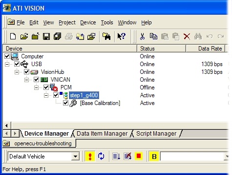
- Troubleshoot
Visually check for the response from actuators that are driven by the OpenECU module (lamps, relays, DC motors, etc.) during power-up. When the observed actuator response is not as expected, then the OpenECU module is not powered up correctly.
Check that the 5V sensor reference output on the OpenECU module is present. When the reference line voltage does not match the expected 5V, then the module is not powered up correctly.
Measure the current drawn by the OpenECU module (electrical current into all VPWR input pins). When the total current is less than 250mA, then the module is not powered up correctly.
- Solution
When fused, check that all fuses are intact.
Check that all VPWR pins have a DC voltage supply of 9V to 16V.
Check that all PWRGND connections are connected to ground.
- Troubleshoot
Ensure OpenECU is powered-up (see Section G.3.2.1, “OpenECU module is not powered-up”).
- Solution
Remove all devices from the CAN bus except the OpenECU module and the ATI Hub.
Note
When communications are established, then the cause may be in the disconnected device(s). Terminating resistors, different CAN baud rate or clashing CAN message ID's are potential causes. Further investigation will be required but is outside the scope of this trouble shooting guide.
Check the 15 pin D-type connector on the back of the ATI Hub if fixed securely.
Check that the ATI CAN connections are fitted correctly. CAN-High (white) and CAN-Low (blue) are connected to the corresponding pins of the OpenECU module.
- Troubleshoot
Ensure OpenECU is powered-up (see Section G.3.2.1, “OpenECU module is not powered-up”).
Ensure the Hub is connected to the Hub correctly (see Section G.3.2.2, “OpenECU module is not connected to the ATI Hub correctly”).
- Solution
Power down the OpenECU module.
Apply 18V DC to the FEPS input pin of the OpenECU module (i.e. use an external power supply between the FEPS pin and ground).
Power up the OpenECU module (powering up with 18V applied to the FEPS pin, forces the OpenECU module to enter reprogramming mode).
When communications is established, flash the module with the strategy that is known to be working. Continue with the following steps:
Wait for flashing to complete.
Remove the 18V DC power from the FEPS input pin of the OpenECU module.
Power cycle the module.
Note
Continuous module resets can be caused by a mistake in the strategy model (e.g. divide by zero) or when a model takes too long to run in its allotted time budget (e.g., a 1ms model rate takes longer than 1ms to complete). It is good practice to review the source model for potential causes of the reset.
When communications is not established, the OpenECU module is not resetting continuously and the problem is potentially with the CAN configuration (see Section G.3.2.4, “CAN baud rate between OpenECU and ATI disagree” and Section G.3.2.5, “CCP CRO and DTO values do not agree with OpenECU”).
- Troubleshoot
Ensure OpenECU is powered-up (see Section G.3.2.1, “OpenECU module is not powered-up”).
Ensure the Hub is connected to the Hub correctly (see Section G.3.2.2, “OpenECU module is not connected to the ATI Hub correctly”).
Ensure the module does not reset continuously (see Section G.3.2.3, “OpenECU module resets continuously”).
- Solution
In ATI Vision, right click on “VNICAN” and select the menu option Properties.
Select the Settings tab.
Select a Bus Frequency of what is expected to match the strategy that is currently flashed onto the module.
Note
When the version of the latest strategy is known, then the bus frequencies of that strategy can be found by opening the strategy in ATI Vision and selecting the menu option File > Properties. The frequency is displayed as “Baudrate” in the Device Settings tab. If the strategy is unknown, then it will be any of the following possible frequencies: 33.333, 50, 62.5, 83.333, 100, 125, 250, 500 or 1000 kBps. Select one at a time until communications are established.
When communications is still not established, then the most likely cause is a mismatch of the CRO and DTO vales between the active strategy in the project and the strategy that is currently flashed onto the module. See Section G.3.2.5, “CCP CRO and DTO values do not agree with OpenECU” on how to change CRO and DTO values.
When communications is established, flash the module with the strategy that has the new desired bus frequency.
Power cycle the module when flashing has completed.
In ATI Vision, right click on “VNICAN” and select the menu option Properties.
Highlight the Settings tab.
Select a “Bus Frequency” of the strategy that is flashed onto the module.
- Troubleshoot
Ensure OpenECU is powered-up (see Section G.3.2.1, “OpenECU module is not powered-up”).
Ensure the Hub is connected to the Hub correctly (see Section G.3.2.2, “OpenECU module is not connected to the ATI Hub correctly”).
Ensure the module does not reset continuously (see Section G.3.2.3, “OpenECU module resets continuously”).
Ensure the CAN baud rate is correct (see Section G.3.2.4, “CAN baud rate between OpenECU and ATI disagree”).
- Solution
Note
You will need to know the CRO and DTO values of the strategy that was last successfully flashed onto module. These values can either be found in the corresponding MATLAB model or from the corresponding strategy (VST) file. Use steps 2 to 6 below to find out what the existing values are. Because the CRO and DTO can be any CAN identifier number, it will be very difficult to establish communications without knowing the values used in the strategy that is currently flashed onto the modules.
Create a copy of the strategy file that needs to be flashed onto the module.
Opening it in ATI Vision and selecting the menu option File > Properties.
In the Device Settings tab, highlight CRO and press the Edit button. Enter the CRO number of the strategy that is currently flashed onto the module and select the OK.
In the Device Settings tab, highlight DTO and press the Edit button. Enter the DTO number of the strategy that is currently flashed onto the module and select the OK.
Save the modified strategy file.
Attach the modified strategy file to the PCM in ATI Vision and make active.
When communications is established, flash the module with the strategy.
Power cycle the module when flashing has completed (comms should no longer be established).
Attach the version of the strategy file with the original CRO and DTO values to the PCM in ATI Vision and make active.
- Troubleshoot
Ensure OpenECU is powered-up (see Section G.3.2.1, “OpenECU module is not powered-up”).
Ensure the Hub is connected to the Hub correctly (see Section G.3.2.2, “OpenECU module is not connected to the ATI Hub correctly”).
Ensure the module does not reset continuously (see Section G.3.2.3, “OpenECU module resets continuously”).
Ensure the CAN baud rate is correct (see Section G.3.2.4, “CAN baud rate between OpenECU and ATI disagree”).
Ensure the CCP CRO and DTO values are correct (see Section G.3.2.5, “CCP CRO and DTO values do not agree with OpenECU”).
- Solution
Check the directory where the Vision strategy file is located. If this directory does not contain a DLL file and the strategy is known to require CCP seed/key security, then copy the relevant file to this directory.
If the directory contains one or more DLL files but CCP seed/key security is still not available, it is possible that the DLL file in this directory may have the correct name but the wrong algorithm. (It may be the algorithm for a different manufacturer or platform, for example). Locate the correct DLL file(s) providing CCP seed/key security algorithms for this application, and copy the file(s) to this directory.
When the DDE tool generates an error about a DDE, the entry (and possibly
related entries) will not be read into MATLAB's workspace. The user must
correct the entry and re-read the data dictionary into the workspace using
the command oe_read_build_list.
When the DDE tool generates a warning about a DDE, the entry will be read
into MATLAB's workspace but some of the attributes about the DDE may be changed.
To remove the warning, the user must change the entry and re-read the data dictionary
into the workspace using the command oe_read_build_list.
The interface tool can generate the following error and warning messages when it processes the command line options presented to the tool.
(error 100): unrecognised command line arguments, try -h or --help for more.
The interface tool has detected that there are command line options which mean nothing to the tool.
(error 101) file 'file name': could not open interface file for reading, 'error message'.
The interface tool could not read the interface file given by 'file name' and the operating system's reason for not being able to do so is given by 'error message'. Correct the reason for failure and try again.
(error 102) file 'file name': could not open AST debug file for writing, 'error message'.
The interface tool could not create or write to the first debug file called 'file name' and the operating system's reason for not being able to do so is given by 'error message'. Correct the reason for failure and try again.
(error 103) file 'file name': could not open AST debug file for writing, 'error message'.
The interface tool could not create or write to the second debug file called 'file name' and the operating system's reason for not being able to do so is given by 'error message'. Correct the reason for failure and try again.
(error 104) file 'file name': could not open code file for writing, 'error message'.
The interface tool could not create or write to the first code file called 'file name' and the operating system's reason for not being able to do so is given by 'error message'. Correct the reason for failure and try again.
(error 105) file 'file name': could not open code file for writing, 'error message'.
The interface tool could not create or write to the second code file called file name and the operating system's reason for not being able to do so is given by 'error message'. Correct the reason for failure and try again.
(error 106) file 'file name': could not open m-script file for writing, 'error message'.
The interface tool could not create or write to the MATLAB m-script file, call file name and the operating system's reason for not being able to do so is given by 'error message'. Correct the reason for failure and try again.
(error 107) file 'file name': could not open generic ASAP2 file for writing, 'error message'.
The interface tool could not create or write to the generic ASAP2 file called file name and the operating system's reason for not being able to do so is given by 'error message'. Correct the reason for failure and try again.
(error 108) file 'file name': could not open INCA ASAP2 file for writing, 'error message'.
The interface tool could not create or write to the ETAS INCA ASAP2 file called file name and the operating system's reason for not being able to do so is given by 'error message'. Correct the reason for failure and try again.
(error 109) file 'file name': could not open Vision ASAP2 file for writing, 'error message'.
The interface tool could not create or write to the ATI Vision ASAP2 file called file name and the operating system's reason for not being able to do so is given by 'error message'. Correct the reason for failure and try again.
(error 110): at least one command option required an ASAP2 file to be generated but no MAP file or ELF information file was specified. Try -h or --help for more information.
The interface tool has been asked to generate an ASAP2 file but has not been told the MAP or ELF information file to derive the addresses of DDEs.
(error 111): the asap2 naming pattern must be one of 'prefix_name', 'prefix.name', 'prefix.name_prefix', 'name', 'name_prefix'.
The interface tool has been told to transform the DDE names when generating an ASAP2 file, but the interface tool does not understand the transformation required (there are only a few pre-determined transforms).
(error 112): the boolean type must be specified as 'u8' or 'float'.
The interface tool has been told to generate ASAP2 boolean types with a specific type, but the interface tool does not understand the type provided.
(error 113): you may specify a Diab or GCC MAP file OR an ELF information file as input, but not both.
The interface tool has been given more than one of a Diab MAP file, a GCC MAP file, Diab ddump file, or a GCC objdump file as input but does not know which to use. Specify only one MAP file or ELF information file as input.
(error 114): you cannot specify data dictionary generation using --output-elf-contents without also specifying an ELF information file to be read.
Using the command line option
--output-elf-contentsthe interface tool has been told to generate a data dictionary file from the contents of a Diab ddump or GCC objdump file (derived from an ELF file) but no such file has been specified with the--diab-ddumpfileoption or--gcc-objfileoption.(error 115) file 'file name': could not open DDE file for writing, 'error message'.
The interface tool could not write to the data dictionary file given by 'file name' and the operating system's reason for not being able to do so is given by 'error message'. Correct the reason for failure and try again (the file may be read-only or locked by another application).
(error 116) file 'file name': could not open [type of] file for writing, 'error message'.
The interface tool could not create or write to the file specified by 'file name' and the operating system's reason for not being able to do so is given by 'error message'. Correct the reason for failure and try again (the file may be read-only or locked by another application).
(error 117): you cannot specify address list output using --output-address-list without also specifying a ELF information file to be read.
The interface tool has been told which file to output the address list to, but it has not been told which Diab ddump or GCC objdump file to read this information from.
(error 118): the compiler must be 'diab_5_5_1_0', 'diab_5_8' or 'diab_5_9'.
The interface tool has been told which compiler is being used, but it does not recognise the compiler so identified.
(error 119) file 'file name': could not open output linker file for writing, 'error message'.
The interface tool could not write to the output linker file given by 'file name' and the operating system's reason for not being able to do so is given by 'error message'. Correct the reason for failure and try again (the file may be read-only or locked by another application).
(error 120): to generate a linker file output you must specify the OpenECU installation base path using the --oe-base-path option.
The interface tool can only output linker file using the
--output-linker-filecommand line option if the--oe-base-pathoption is also used to specify the path to the OpenECU installation.(error 121) file 'file name': could not open linker source file for reading, 'error message'.
The interface tool could not read from the linker source file given by 'file name' and the operating system's reason for not being able to do so is given by 'error message'. Correct the reason for failure and try again.
(error 122): the compiler must be specified when outputting a linker file for the 'target name' target.
For any target that supports more than one compiler, the interface tool needs to be passed the compiler id using the
--compiler-idcommand line option when outputting the linker file using the--output-linker-fileoption.(error 123): no input program images. Please specify values for --img-app and --img-cal.
In order to use the
--output-s-recoption, the options--img-appand--img-calmust be specified.(error 124): no diab mapfile. please specify value for --diab-mapfile.
In order to use the
--output-s-recoption, the option--diab-mapfilemust be specified.(error 125): could not open s-record file for writing.
The tool tried to create the file specified by
--output-s-rec, but failed. This often means that the file already exists and is read-only, or the file was specified in a non-existing directory.(error 126): could not open application image file for reading.
The tool tried to read the file specified by
--img-app, but failed. This often means that the file does not exist.(error 127): could not open calibration image file for reading.
The tool tried to read the file specified by
--img-cal, but failed. This often means that the file does not exist.(error 128): could not open linker file excerpt for reading.
The tool tried to read the file specified by
--ld-excerpt-file, but failed. This often means that the file does not exist.(error 129): cannot check data dictionary entity data types using
--check-dde-data-types.The tool received an error when checking for the ELF file. When using the
--check-dde-data-typesoption, the ELF file must be specified.(error 130): Unable to validate license.
The tool received an error while verifying the license. Verify that OpenECU is installed correctly with a valid license.
(error 200): found internal error — attempting to set the handle for file 'filename' a second time.
The interface tool has found in internal error. Please contact OpenECU support if this error occurs.
(error 201) file 'file name': could not close file.
The interface tool could not close the file given by 'file name' after the file was opened to be read or written to. In this case, the interface tool may leave a temporary file called 'file name' after the tool completes.
(error 202): found internal error — cannot remove file 'file name' when the type of file is unknown.
The interface tool has found in internal error. Please contact OpenECU support if this error occurs.
(error 203) file 'file name': could not delete temporary file.
The interface tool could not close the file given by 'file name' after the file was opened to be read or written to. In this case, the interface tool may leave a temporary file called 'file name' after the tool completes.
(error 204): found internal error — repeated file registration for 'file name'.
The interface tool has found in internal error. Please contact OpenECU support if this error occurs.
(error 300) file 'file name': could not open map file for reading, 'error message'.
The interface tool could not read the mapfile given by 'file name' and the operating system's reason for not being able to do so is given by 'error message'. Correct the reason for failure and try again.
(error 3001) file 'file name': label 'name' is not defined by 'map file' but is required for ASAP2 generation.
The interface tool has read a DDE called 'name' from the DDE file called 'file name' but cannot find the address of the DDE in the Diab MAP file called 'map file'. This often occurs because there is no extern C variable with the name 'name' (either because the variable does not exist or because it is not declared
extern).(error 3002) file 'file name': label 'name' is not defined by 'file' but is required for ASAP2 generation of DDE 'dde name'.
The interface tool has read a DDE called 'dde name' from the DDE file called 'file name' but cannot find the address of the DDE in the Diab MAP or ddump file called 'file'. This often occurs because there is no extern C variable with the name 'name' (either because the variable does not exist or because it is not declared
extern).(error 3003): found internal error while creating an ASAP2 entry for DDE 'dde name' — no X-axis DDE 'name' found.
The interface tool has found in internal error. Please contact OpenECU support if this error occurs.
(error 3004): found internal error while creating an ASAP2 entry for DDE 'dde name' — no Y-axis DDE 'name' found.
The interface tool has found in internal error. Please contact OpenECU support if this error occurs.
(error 3005): found internal error while creating an ASAP2 entry for DDE 'dde name' — DDE class 'type' is unsupported.
The interface tool has found in internal error. Please contact OpenECU support if this error occurs.
(error 3006): found internal error while searching for an 'os-native' statement — not found but should be present.
The interface tool has found in internal error. Please contact OpenECU support if this error occurs.
(error 3007): found internal error while searching for task 'name' required by an ATI shadow table — not found but should be present.
The interface tool has found in internal error. Please contact OpenECU support if this error occurs.
(error 3008): found internal error while creating a unique ASAP2 identifier for DDE 'dde name' — too many unique conversions.
The interface tool has found in internal error. Please contact OpenECU support if this error occurs.
(warning 3009) line 'number' of 'file name': the DDE name 'dde name' is either too long for an ASAP2 identifier (max 32 characters), or clashes with another identifier, and has been changed to 'short dde name' for ASAP2 file generation.
The interface tool has read a DDE file called 'file name' and at line 'number' has found a DDE called 'dde name' which is too long for an ASAP2 file. The DDE has been changed to 'short dde name' which is guaranteed to be unique and be less than 33 characters long.
(warning 3010) file 'file name': label 'name' is not defined by 'map file' but is required for ASAP2 generation, DDE not added to ASAP2 file.
The interface tool has read a DDE called 'name' from the DDE file called 'file name' but cannot find the address of the DDE in the Diab MAP file called 'map file'. This often occurs because there is no extern C variable with the name 'name' (either because the variable does not exist or because it is not declared
extern), or because the DDE file is out of date. The warning does not stop generation of the ASAP2 file, but the DDE will not be added to the ASAP2 file.(error 3011): found internal error while creating an ASAP2 entry for DDE 'dde name' -- X-axis 'dde' must have at least two elements. (Note unspecified array size in code is currently read as one element.)
The interface tool needs to generate an ASAP2 axis definition for a calibration map named 'dde name' but has found an internal error. If this error occurs, please contact OpenECU technical support.
(error 3012): found internal error while creating an ASAP2 entry for DDE 'dde name' — X-axis DDE 'name' must be 'caxis' Class.
The interface tool needs to generate an ASAP2 axis definition for a calibration map named 'dde name' but has found an internal error. If this error occurs, please contact OpenECU technical support.
(error 3013): found internal error while creating an ASAP2 entry for DDE 'dde name' — Y-axis DDE 'name' must be 'caxis' Class.
The interface tool needs to generate an ASAP2 axis definition for a calibration map named 'dde name' but has found an internal error. If this error occurs, please contact OpenECU technical support.
(error 3014): found internal error while creating an ASAP2 entry for DDE 'dde name' -- Y-axis DDE 'name' must be 1-D array.
The interface tool needs to generate an ASAP2 axis definition for a calibration map named 'dde name' but has found an internal error. If this error occurs, please contact OpenECU technical support.
(error 3015): found internal error while creating an ASAP2 entry for DDE 'dde name' -- Y-axis 'dde' must have at least two elements. (Note unspecified array size in code is currently read as one element.)
The interface tool needs to generate an ASAP2 axis definition for a calibration map named 'dde name' but has found an internal error. If this error occurs, please contact OpenECU technical support.
(error 3016): found internal error while creating an ASAP2 entry for DDE '%s' — Y-axis DDE '%s' must also be in C-style data dictionary
If the calibration map DDE 'dde name' is declared in a C-style data dictionary file then the x-axis DDE 'name' must also be declared in a C-style data dictionary. It is not possible to mix axis and map definitions between prefix and C style data dictionaries.
(error 3017): found internal error while creating an ASAP2 entry for DDE 'dde name' — X-axis DDE 'name' must also be in C-style data dictionary.
If the calibration map DDE 'dde name' is declared in a C-style data dictionary file then the y-axis DDE 'name' must also be declared in a C-style data dictionary. It is not possible to mix axis and map definitions between prefix and C style data dictionaries.
(error 3018): found internal error while creating an ASAP2 entry for DDE 'dde name' -- map array must be array.
The interface tool needs to generate an ASAP2 map definition but has found an internal error.
(error 3019): found internal error while creating an ASAP2 entry for DDE 'dde name' — 2D array but only Xaxis specified.
The interface tool needs to generate an ASAP2 map definition for a two-dimensional calibration map DDE 'dde name' but only one axis has been specified. Both the Xaxis and Yaxis columns must be specified.
(error 3020): found internal error while creating an ASAP2 entry for DDE 'dde name' -- array size incompatible with axis size(s).
The interface tool needs to generate an ASAP2 map definition for a calibration map DDE 'dde name' but the equivalent C variable does not match the size of the map axes. For instance, a map with 4 elements in the x-axis and 10 elements in the y-axis, must have an equivalent C variable with 40 elements.
(warning 3021) file 'file name': one-dimensional array expected for 'dde name'; now treated as such.
A DDE called 'dde name' is expected to be a one dimensional array (for instance, because it's Class column specifies the DDE to be an axis or a string) but the equivalent C variable is not one dimensional (but should be).
(error 3022): file 'file name': label 'dde name' according to 'file' has more than 3 final array dimensions.
The interface tool can generate ASAP2 entities with up to 3 dimensions but no more, because the ASAP2 syntax does not allow further dimensions. However, the interface tool will break up arrays with more than 1 or 2 dimensions into multiple DDEs of smaller dimension. If this error occurs, please contain OpenECU technical support.
(error 3023): C-style data dictionary specified in dde_filename not allowed without ELF information file.
For ASAP2 generation, C-style data dictionaries can only be used if a Diab ddump or GNU objdumb ELF information file file is also specified (not just a map file). Otherwise the tool cannot obtain the types and sizes of the variables detailed in the data dictionary.
(error 3024): found internal error while creating an ASAP2 entry for DDE 'dde name' -- X-axis DDE 'name' must be 1-D array.
The interface tool needs to generate an ASAP2 axis definition for a calibration map named 'dde name' but has found an internal error. If this error occurs, please contact OpenECU technical support.
(warning 3025): string array 'dde name' had zero size, so a default size of 'bytes' has been used, hence it may display incorrectly.
The DDE string 'dde name' has an equivalent C variable in the Diab ddump file with no information about the string's size. The interface tool generates an entry for the DDE but with a size 'bytes' long which probably does not match the actual string length. To avoid this, use an explicit array size in the C declaration.
(error 3026): found internal error while creating an ASAP2 entry for DDE 'dde name' — too many array dimensions for map data.
The interface tool needs to generate an ASAP2 map definition for a calibration map DDE 'dde name' but the equivalent C variable has more dimensions than the calibration map.
(warning 3028): the application name, 'name', contains characters not supported by ASAP2 standards; the application name has been replaced with 'updated name'.
The
application namegenerated in the ASAP2 file contained characters that were unacceptable in accordance to ASAP2 standards. The calibration tool Vector CANape doesn't support use of such ASAP2 files. The C-API interface tool has been updated to generate ASAP2 files containing characters of theapplication namethat are in accordance with the standards.(error 3332) shadow table references task (task) but that task as not been declared.
The shadow table entry must reference a declared task. This is the task which is to carry out the calibration tool writes. Here a task is referenced which has not been declared.
(error 3333) more than four shadow-table statements are present.
The tool does not currently support more than four shadow table statements.
(warning 3334) shadow table must have number of entries in the range [1, 256].
The number of entries in the shadow table is not within the supported range.
(error 400): found internal error while searching for an 'os-native' statement — not found but should be present.
The interface tool has found in internal error. Please contact OpenECU support if this error occurs.
(error 402): while creating automatic adaptive DDE 'dde name' an existing DDE of the same name was found — do not replicate adaptive DDEs in DDE files.
The interface tool has tried to create an automatic adaptive DDE for the corresponding DDE named 'dde name' but found that one is already present. This situation occurs because one of the DDE files contains a definition for a DDE that the interface tool requires — rename the DDE.
(error 403): there is no DDE for the adaptive 'adaptive name'.
The interface tool has read an interface file which declares some adaptive data using the
adaptive-liststatement but there is no corresponding DDE for the 'adaptive name'. Update one of the DDE files to include a definition of the adaptive data.(error 404): while creating automatic tune DDE 'dde name' an existing DDE of the same name was found -- do not replicate tune DDEs in DDE files.
The interface tool has tried to create an automatic Tune DDE for the corresponding DDE named 'dde name' but found that one is already present. This situation occurs because one of the DDE files contains a definition for a DDE that the interface tool requires — rename the DDE.
(error 405): there is no DDE for the tune 'tune name'.
The interface tool has read an interface file which declares some Tune data using the
tune-liststatement but there is no corresponding DDE for the 'tune name'. Update one of the DDE files to include a definition of the adaptive data.(error 406): found internal error — could not find 'named' node.
The interface tool has found in internal error. Please contact OpenECU support if this error occurs.
(error 407): found internal error — could not find 'named' declaration.
The interface tool has found in internal error. Please contact OpenECU support if this error occurs.
(error 500) line 'number' of 'file name': incomplete string literal, or string literal containing unsupported characters.
The interface tool has read an interface file called 'file name' and found an error at line 'number' containing a string without a closing quote, or a string containing unsupported characters (only the printable ASCII characters are valid (ranging from character 32 (space) through to character 126 (tilde)). Change the interface file to contain a valid string.
(error 501) line 'number' of 'file name': incomplete comment.
The interface tool has read an interface file called 'file name' and found an error at line 'number' containing a comment without the final
*/characters. Change the interface file to complete the comment.(error 502) line 'number' of 'file name': unexpected character 'letter'.
The interface tool has read an interface file called 'file name' and found an error at line 'number' containing text which the tool does not expect to see.
(error 503) line 'number' of 'file name': could not read number.
The interface tool has read an interface file called 'file name' and at line 'number' the interface tool could not convert the text into a number. Adjust the number to be valid and in the range [0, 2147483647].
(error 504) line 'number' of 'file name': number must be positive.
The interface tool has read an interface file called 'file name' and at line 'number' the interface tool found an unexpected negative number. Adjust the number to be in the range [0, 2147483647].
(error 505) line 'number' of 'file name': number must be less than 2147483648.
The interface tool has read an interface file called 'file name' and at line 'number' found a number which was too large. Adjust the number to be in the range [0, 2147483647].
(error 506) line 'number' of 'file name': cannot use the '-' character in an identifier.
The interface tool has read an interface file called 'file name' and found a '-' character as part of an identifier at line 'number'. Rename the identifier without the '-' character.
(error 600): found internal error — unexpected error.
The interface tool has found in internal error. Please contact OpenECU support if this error occurs.
(error 601) line 'number' of 'file name': repeated identifier.
The interface tool has read an interface file called 'file name' and at line 'number' has found an identifier that has been used elsewhere in the interface file. All identifiers must be unique.
(error 602) line 'number' of 'file name': identifier is more than 31 characters in length.
The interface tool has read an interface file called 'file name' and at line 'number' has found an identifier with more than 31 characters. All identifiers must be limited to a maximum of 31 characters.
(error 603) line 'number' of 'file name': unexpected input.
The interface tool has read an interface file called 'file name' and at line 'number' has found a syntax error.
(error 604) line 'number' of 'file name': unexpected end of file.
The interface tool has read an interface file called 'file name' and at line 'number' has encountered the end of the file while still expecting to see more detail in the interface file. This may occur if there is a missing close brace (
}) in the file.
(error 700) file 'file name': could not open tabbed DDE file for reading, 'error message'.
The interface tool could not read the DDE file named 'file name' and the operating system's reason for not being able to do so is given by 'error message'. Correct the reason for failure and try again.
(error 800) file 'file name': could not open units file for reading, 'error message'.
The interface tool could not read the units file named 'file name' and the operating system's reason for not being able to do so is given by 'error message'. Correct the reason for failure and try again.
(error 900) line 'number' of 'file name': from within the 'compound' statement, there is a missing 'assignment' statement.
The interface tool has read an interface specification file called 'file name' and at line 'number' has found a compound statement with a missing assignment statement called 'assignment'. In this case, the interface tool is expecting the assignment statement to be present (i.e., the assignment statement is not optional).
(error 901) file 'file name': within the interface file, there is a missing 'compound' statement.
The interface tool has read an interface specification file called 'file name' and at line 'number' has found that the file is missing a compound statement called 'compound'. In this case, the interface tool is expecting the compound statement to be present (i.e., the statement is not optional).
(error 1001): line 'number' of 'file name': 'dde name' is an invalid name for a data dictionary entry (must be greater than 3 characters long).
All data dictionary entry names must be greater than 3 characters long. Change the name so it is at least 4 characters in length.
(error 1002): line 'number' of 'file name': 'dde name' is an invalid name for a data dictionary entry (must be less than 256 characters long).
(error 1003): line 'number' of 'file name': 'dde name' is an invalid name for a prefix-style data dictionary entry (must not start with a digit or a '_' character).
To provide compatibility with Simulink, prefix-style DDE names must not start with an underscore. To provide compatibility with Simulink and C compilers, prefix-style DDE names must not start with a digit.
(error 1004): line 'number' of 'file name': 'dde name' is an invalid name for a prefix-style data dictionary entry (must only use characters 'a' through 'z', 'A' through 'Z', '0' through '9' or '_').
Simulink and many C compilers disallow certain characters to appear in signal and variable names. Change the name to avoid the use of these characters.
(error 1005): line 'number' of 'file name': 'dde name' is an invalid name for a calibration map (must end in '_x' or '_y' or '_z').
The tool has recognised that the DDE forms part of a calibration map but does not conform to the rules for naming these entities. See Section 5.2.5, “Naming rules” for more details.
(error 1006): line 'number' of 'file name': 'dde name' is an invalid name for an item which is not a calibration map (must not end in '_x' or '_y' or '_z').
The tool has recognised that the DDE does not form part of a calibration map and does not conform to the rules for naming these entities. See Section 5.2.5, “Naming rules” for more details.
(error 1007): line 'number' of 'file name': 'dde name' is a calibration but has no value.
The entry is a calibration of some sort but does not contain a default calibration value, which it must do.
(error 1008): line 'number' of 'file name': 'dde name' has an invalid value 'text of value'.
The tool could not convert the text of the value into a numeric value. All numeric values must be scalar and represent a real value. The following are examples of valid values: 3.14, 10, 10., .001, 1e8, 3.14e-10, 0e0.
(error 1009): line 'number' of 'file name': 'dde name' must be a vector or a matrix surrounded by '[' and ']').
The tool has recognised that the entry forms part of a calibration map but that the value or values supplied are not valid expressions, either of a vector or of a matrix. Values for an axis (_x or _y) should be given as a vector. Values for the data points (_z) should be given as a vector for 1-d maps or as a matrix for 2-d maps.
- vector
A vector takes the form [numbers separated by spaces]. An example of a vector containing three elements would be: [10, 15, 20].
- matrix
A matrix takes the form [vectors separated by semicolons]. An example of a matrix containing three rows and columns would be: [1 2 3; 10 20 30; 100; 200; 300].
(error 1010): line 'number' of 'file name': the row sizes for 'dde name' differ."
The tool requires map axes and map data to match in size. For instance, a 1-d map with 5 elements in the x-axis, requires 5 elements in the z-data. Change the axis and data elements to match in size.
(error 1011): line 'number' of 'file name': the row size for 'dde name' must be at least 2 entries.
The tool requires that map axes and map data have at least 2 elements. For instance, if a 1-d map had 1 element for the x-axis and therefore 1 element for the z-data, the map lookup would be equivalent to a constant block.
(error 1012): line 'number' of 'file name': the row data for 'dde name' must be 1xN matrix.
The tool requires that any map axis be a vector (a 1xN matrix), the OpenECU 1-d and 2-d map lookup blocks do not work with other sized matrices.
(error 1013): line 'number' of 'file name': the units for 'dde name' is too long (must be less than 'number' characters long).
The units field must be less than 32 characters long by default so that it can be exported into other file formats (e.g., ASAP2 file) without issues. Either change the units so it contains less than 32 characters, or change the limit using the Simulink Model Configuration Option 'Maximum data dictionary entry name length'.
(error 1014): line 'number' of 'file name': the units for 'dde name' cannot contain single quote characters.
The units field must not contain single quote characters so that it can be exported into other file formats (e.g., ASAP2 file) without issues.
(error 1015): line 'number' of 'file name': the units for 'dde name' cannot contain double quote characters.
The units field must not contain double quote characters so that it can be exported into other file formats (e.g., ASAP2 file) without issues.
(error 1016): line 'number' of 'file name': the description for 'dde name' is too long (must be less than 256 characters long).
The description field must contain less than 256 characters so that it can be exported into other file formats (e.g., ASAP2 file) without issues.
(error 1017): line 'number' of 'file name': the description for 'dde name' cannot contain single quote characters.
The description field must not contain single quote characters so that it can be exported into other file formats (e.g., ASAP2 file) without issues.
(error 1018): line 'number' of 'file name': the description for 'dde name' cannot contain double quote characters.
The description field must not contain double quote characters so that it can be exported into other file formats (e.g., ASAP2 file) without issues.
(error 1019): line 'number' of 'file name': 'dde name' has an unspecified type (must be one of: int8_T, S8, uint8_T, U8, int16_T, S16, uint16_T, U16, int32_T, S32, uint32_T, U32, real_T, F32, BOOL).
The type of the DDE must be one of the types that MATLAB/Simulink/RTW supports so that simulation and code generation can occur without error. See Section 4.2.2.2, “Data dictionary files” for more.
(error 1020): line 'number' of 'file name': 'dde name' has an invalid type 'type text' (must be one of: int8_T, S8, uint8_T, U8, int16_T, S16, uint16_T, U16, int32_T, S32, uint32_T, U32, real_T, F32, BOOL).
The type of the DDE has been specified but it is not one of the types supported by MATLAB/Simulink/RTW. See Section 4.2.2.2, “Data dictionary files” for more.
(error 1021): line 'number' of 'file name': 'dde name' represents map calibration data and must have a real_T or F32 type.
OpenECU 1-d and 2-d map lookup blocks only work with floating point types (integer types are unsupported in these blocks). Change the type of the map axis or map data to be real_T or F32.
(error 1022): line 'number' of 'file name': 'dde name' has an invalid number 'x' for the accuracy column.
The tool was expecting to find a number in the accuracy field but found something else instead.
(error 1023): line 'number' of 'file name': 'dde name' has a maximum value but no minimum.
The tool expects to see both a minimum and a maximum for the DDE if one or the other is present. The DDE must either have no minimum and maximum specified or both.
(error 1024): line 'number' of 'file name': 'dde name' has a minimum value but no maximum.
The tool expects to see both a minimum and a maximum for the DDE if one or the other is present. The DDE must either have no minimum and maximum specified or both.
(error 1025): line 'number' of 'file name': 'dde name' has an invalid number 'x' for the minimum value.
The tool was expecting to find a number in the minimum field but found something else instead.
(error 1026): line 'number' of 'file name': 'dde name' has boolean type so its minimum must be zero.
The type of the DDE is a boolean, so the minimum value must be zero but the tool found a different value for the minimum field.
(error 1027): line 'number' of 'file name': 'dde name' has an invalid number 'x' for the maximum value.
The tool was expecting to find a number in the maximum field but found something else instead.
(error 1028): line 'number' of 'file name': 'dde name' has boolean type so its maximum must be one.
The type of the DDE is a boolean, so the maximum value must be one but the tool found a different value for the maximum field.
(error 1029): line 'number' of 'file name': 'dde name' has an invalid number 'x' for the scale value.
The tool was expecting to find a number in the scale field but found something else instead.
(error 1030): line 'number' of 'file name': 'dde name' has an invalid number 'x' for the offset value.
The tool was expecting to find a number in the scale field but found something else instead.
(error 1032): line 'number' of 'file name': 'dde name' has a different matrix size from the X-axis matrix size.
The tool has detected that the z-data matrix size in for the x-axis differs in size from the x-axis. The size of the axes and data must match.
(error 1033): line 'number' of 'file name': 'dde name' has a different matrix size from the Y-axis matrix size.
The tool has detected that the z-data matrix size in for the y-axis differs in size from the y-axis. The size of the axes and data must match.
(error 1034): line 'number' of 'file name': 'dde name' has multiple rows but no Y-axis data dictionary entry.
The tool has detected that the z-data for a map contains data for both the x and y axes but no y-axis DDE has been declared.
(error 1035): line 'number' of 'file name': 'dde name' does not have a corresponding X-axis data dictionary entry.
The tool has detected that there is z-data for a map lookup but no corresponding x-axis DDE has been declared.
(error 1036): line 'number' of 'file name': 'dde name' must be a scalar.
The tool has read more than one value for the scalar calibration. Only one value can be specified.
(error 1037): line 'number' of 'file name': an unnamed column was found — skipping entire data dictionary.
The tool has found a column without a name. This can occur if two tab characters are placed next to each other
Name Value Units Description Type Accuracy Min Max Offset Scale Cref(error 1038): line 'number' of 'file name': column 'name' is only allowed in 'style'-style data dictionaries — skipping entire 'style'-style data dictionary.
The tool has found a column in the title line of the data dictionary that it does not recognise. The only valid column names in a prefix-style data dictionary file are:
Name Value Units Description Type Enums Accuracy Min Max Offset Scale CrefThe only valid column names in a C-style data dictionary file are:
Name Units Description Accuracy Min Max Offset Scale Class Xaxis Yaxis Lookup(error 1039): line 'number' of 'file name': 'dde name' is an invalid Cref for a data dictionary entry (must not start with a digit).
The tool has found an invalid name for the Cref column. This is an internal error. Please contact OpenECU support.
(error 1040): line 'number' of 'file name': 'dde name' is an invalid Cref for a data dictionary entry (must only use characters 'a' through 'z', 'A' through 'Z', '0' through '9' or '_').
The tool has found an invalid name for the Cref column. This is an internal error. Please contact OpenECU support.
(error 1041): line 'number' of 'file name': 'dde name' is a reserved name for a data dictionary entry (must not use the 'mpl' prefix).
The tool has found a DDE with a name which starts with
mpl. This prefix is reserved for OpenECU use. Rename the DDE variable using a different prefix.(error 1042): line 'number' of 'file name': the 'field_name' field must be present in [style]-style data dictionaries — skipping entire data dictionary.
The tool has found the title line but could not locate all the necessary fields/columns. At a minimum, the following fields/columns must be present in prefix-style data dictionaries:
Name Value Units Description Type Min MaxAnd for C-style data dictionaries, the following fields/columns must be present:
Name Units Description Class Min MaxIn both cases, the
Namefield must be first.(error 1043): line 'number' of 'file name': 'dde name' is an invalid [object] name for a data dictionary entry (must be greater than 3 characters long).
All data dictionary entry enumeration names must be greater than 3 characters long. Change the name so it is at least 4 characters in length.
(error 1044): line 'number' of 'file name': 'dde name' is an invalid [object] name for a data dictionary entry (must be less than 'number' characters long).
Some versions of Simulink and some C compilers disallow names that contain more than 31 characters. Some ASAP2 calibration tools disallow names that contain more than 32 characters. Either change the name so it contains less than the character limit, or change the limit using the Simulink Model Configuration Option 'Maximum data dictionary entry name length'.
(error 1045): line 'number' of 'file name': 'dde name' is an invalid [object] name for a data dictionary entry (must not start with a digit or a '_' character).
Simulink and C compilers disallow names that start with a digit or '_' character. Change the DDE name to start with a letter.
(error 1046): line 'number' of 'file name': 'dde name' is an invalid [object] name for a data dictionary entry (must only use characters 'a' through 'z', 'A' through 'Z', '0' through '9' or '_').
Simulink and C compilers disallow certain characters to appear in names. Change the name to avoid the use of these characters.
(error 1047): line 'number' of 'file name': 'dde name' is an invalid [object] name for a data dictionary entry (must not end in '_x' or '_y' or '_z').
The tool has recognised that the referenced enumeration looks like a map DDE. Rename the enumeration reference so it does not end like a map.
(error 1048): line 'number' of 'file name': 'dde name' is a reserved name for a data dictionary enumeration entry (must not use the 'mpl' prefix).
The tool has found a DDE with an enumerated name which starts with
mpl. This prefix is reserved for OpenECU use. Rename the DDE variable using a different prefix.(error 1049): line 'number' of 'file name': 'dde name' uses an enumeration 'enum name' that is not declared in any data dictionary.
The tool has found an enumeration reference for the DDE named 'dde name' that does not exist in any data dictionary. Change the enumeration reference to a data dictionary entry that does exist.
(error 1050): line 'number' of 'file name': 'dde name' uses an enumeration 'enum_name' which has a non-scalar value.
The tool has found a reference to an enumeration which has a non-scalar value. All enumerations must be single valued entries.
(error 1051): line 'number' of 'file name': 'dde name' uses enumerations 'enum_name' and 'enum_name' which have the same value.
The tool has found a data dictionary entry which refers to two enumerations but both enumerations have the same value. Enumerations for one data dictionary entry must have unique values.
(error 1052): line 'number' of 'file name': 'dde name' has a value less than its type allows.
The tool has found a value for a data dictionary entry which has a value outside the range of its type.
(error 1053): line 'number' of 'file name': 'dde name' has a value greater than its type allows.
The tool has found a value for a data dictionary entry which has a value outside the range of its type.
(error 1054): line 'number' of 'file name': 'dde name' must not have a scale value of zero.
The tool has found a DDE with a scaling factor of zero. This is disallowed, as the reciprocal of the factor is used by OpenECU tools and calibration tools.
(error 1055): line 'number' of 'file name': 'dde name' has no corresponding DDE called 'z-data dde name'.
The tool has found a x-axis DDE without a corresponding z-axis DDE, both are needed to create a 1-d map.
(error 1056): line 'number' of 'file name': 'dde name' has no corresponding DDE called 'z-data dde name'.
The tool has found a y-axis DDE without a corresponding z-axis DDE, both are needed to create a 2-d map.
(error 1057): line 'number' of 'file name': 'dde name' is a displayable with a value.
The tool has found a displayable DDE with a value, only calibration DDEs can have values.
(error 1058): line 'number' of 'file name': 'dde name' has a minimum smaller than its type allows.
The tool has found a DDE which has a minimum value less than the type of the DDE can store. The minimum or type must be adjusted.
(error 1059): line 'number' of 'file name': 'dde name' has a maximum larger than its type allows.
The tool has found a DDE which has a maximum value greater than the type of the DDE can store. The maximum or type must be adjusted.
(error 1060): line 'number' of 'file name': 'dde name' has duplicated enumeration 'enum name'."
The tool has found a DDE which has a repeated enumeration in the DDE's enumeration list. Duplicated enumerations are disallowed.
(error 1061): line 'number' of 'file name': 'class' is an invalid Class for a data dictionary entry (must be one of: 'c', 'cmap', 'caxis', 'cstring', 'carray', 'd', 'darray').
The string 'class' given in the Class column is not one of the allowed types for this DDE.
(error 1062): line 'number' of 'file name': enum 'c identifier' has an invalid byte size = 'bytes'.
The interface tool has found an enumeration with name 'c identifier' which has a byte size it does not recognise. If this error occurs please contact OpenECU technical support.
(error 1063): line 'number' of 'file name': variable 'c identifier' is a pointer; this is not supported for ASAP2 generation.
The interface tool can generate ASAP2 files but ASAP2 files cannot represent pointers. DDE references to C variables which have pointer type are therefore rejected.
(error 1064): line 'number' of 'file name': variable 'c identifier' is a bitfield; this is not supported for ASAP2 generation.
The interface tool cannot yet generate ASAP2 files that access bitfields. Adjust the data structure to avoid using bitfields or copy the bitfields of interest to other variables which are accessible.
(error 1065): line 'number' of 'file name': variable 'c identifier' has a type not currently supported for ASAP2 generation of 'value'.
The interface tool has found type information for a C variable that it does not know how to handle. If this message occurs, please contact OpenECU technical support.
(error 1066): line 'number' of 'file name': variable 'c identifier' has class cstring but is not a byte array.
A C-style DDE has been classed as a string but the type of the equivilent C variable is not signed or unsigned char (wide characters are not supported). Either change the C variable to have an appropriate type of change the class of DDE.
(error 1067): line 'number' of 'file name': variable 'dde name' is not class cmap yet has Xaxis, Yaxis and/or Lookup entries.
A C-style DDE has information in the Xaxis, Yaxis or Lookup columns but the DDE is not a calibration map. Only calibration maps should have information in the Xaxis, Yaxis or Lookup columns.
(error 1068): line 'number' of 'file name': variable 'dde name' used in map must have real_T (float) type.
OpenECU 1-d and 2-d map lookup blocks only work with floating point types (integer types are unsupported in these blocks). Change the type of the map axis or map data to be real_T or F32.
(error 1069): line 'number' of 'file name': variable 'dde name' has Lookup entry 'name' which caused an unexpected error.
An internal error has occurred in the interface tool. If this error occurs, please contact OpenECU technical support.
(error 1070): line 'number' of 'file name': variable 'dde name' has x and y Lookup entries 'string' but no Yaxis entry.
The calibration map with 'dde name' is 2d and has an x-axis Lookup DDE but no y-axis Lookup DDE. Calibration maps must have a lookup DDE for each map axis.
(error 1071): line 'number' of 'file name': variable 'dde name' has Lookup entry 'name' which is not found in ELF data.
The lookup DDE 'name' for calibration map DDE 'dde name' doesn't exist in the Diab ddump file. Check that the spelling is correct, that the equivalent C variable is declared and not optimised away by the compiler.
(error 1072): line 'number' of 'file name': variable 'dde name' has Lookup entry 'name' which has no corresponding DDE, removing lookup variables from map.
The lookup DDE 'name' for calibration map DDE 'dde name' doesn't exist as a DDE in any of the other DDE files. The lookup DDE must be declared in one of the DDE files.
(error 1073): line 'number' of 'file name': variable 'dde name' has Lookup entry 'name' which does not have Class 'd'.
The lookup DDE 'name' for calibration map DDE 'dde name' is declared as something other than a displayable (Class column set to 'd'). Only displayable variables can be used as lookups to calibration maps.
(error 1074): line 'number' of 'file name': variable 'dde name' has Lookup entry 'name' which does not have type real_T (float).
The lookup DDE 'name' for a calibration map DDE 'dde name' must have single precision floating point type to correctly match the C-API to the map lookup functions.
(error 1075): line 'number' of 'file name': variable 'dde name' has Xaxis and Yaxis but only one Lookup entry; should have nothing or two.
The calibration map with 'dde name' is 2d and has one lookup DDE. Calibration maps must have a lookup DDE for each map axis. Check that the Lookup column does not specify only a y-axis lookup DDE.
(error 1076): line 'number' of 'file name': 'dde name' is not found in the ELF information file output, contains an out of range array index, or is declared but not referenced in the source code.
A DDE is declared in the data dictionary but the corresponding varaible could not be found in the Diab ddump or GNU objdump output file. Check the name for spelling mistakes or add the corresponding variable to the application C code.
(error 1077): line 'number' of 'file name': map variable 'dde name' has no Xaxis or Yaxis specified.
A calibration map specified by a C-style DDE has neither the Xaxis and Yaxis DDEs specified. A 1d calibration map must have the Xaxis specified, a 2d calibration map must have both the Xaxis and Yaxis specified.
(error 1078): line 'number' of 'file name': 'dde name' is not found in the ddump ELF file output, contains an out of range array index, or is declared but not referenced in the source code.
The name for a C-style data dictionary entity wasn't present in the final linked application image and therefore cannot be processed. Check the name for spelling mistakes or add the corresponding variable to the application C code.
(error 1079): line 'number' of 'file name': 'dde name' is an invalid name for a C-style data dictionary entry (must resolve to a C identifier).
The name for a C-style data dictionary entity doesn't conform to the allowed scheme. The name of the DDE must be changed.
(error 1080): line 'number' of 'file name': variable 'dde name' has Lookup entry 'string' but should have one identifier or two separated by a comma.
The Lookup column for DDE 'dde name' has an unexcepted value of 'string'. Instead the Lookup column should have one DDE name or two DDE names separated by a comma.
(error 1081): line 'number' of 'file name': unexpected information at end of line — skipping entire data dictionary.
The tool has found a DDE line containing more information that there are columns. Remove the additional information and tab characters, or declare an additional column in the title line of the DDE file.
(error 1082): line 'number' of 'file name': 'dde name' is an invalid name for a C-style data dictionary entry (must not start with a digit character).
To provide compatibility with C compilers, C-style DDE names must not start with a digit.
(error 1083): line 'number' of 'file name': 'dde name' is an invalid name for a C-style data dictionary entry (must only use characters 'a' through 'z', 'A' through 'Z', '0' through '9' or '_', '.', '[', ']').
The interface tool accepts a subset of the C lanaguage syntax for variable names, array and structure member access.
(error 1085): line 'number' of 'file name': column 'name' is unrecognised — skipping entire data dictionary.
The tool has found a column with a name it does not recognise, i.e., not one of the allowed column names. The only valid column names in a prefix-style data dictionary file are:
Name Value Units Description Type Enums Accuracy Min Max Offset Scale CrefThe only valid column names in a C-style data dictionary file are:
Name Units Description Accuracy Min Max Offset Scale Class Xaxis Yaxis Lookup(error 1086): line 'number' of 'file name': DDE 'dde name' has Lookup entry 'string' but should have none, one or two identifiers separated by a comma.
The Lookup column for DDE 'dde name' has an unexcepted value of 'string'. Instead the Lookup column should have one DDE name or two DDE names separated by a comma.
(error 1087): line 'number' of 'file name': 'dde name' is a constant but has no value.
The entry is a constant but does not contain a default value, which it must do.
(error 1100) file 'file name': could not open 'ELF-type' output file for reading, 'error message'.
The interface tool could not read the Diab ddump or GNU objdump file named 'file name' and the operating system's reason for not being able to do so is given by 'error message'. Correct the reason for failure and try again.
(error 1101): file 'file name': variable with no name attribute in ELF information file at line 'number'.
The interface tool has found an unnamed attribute in the Diab ddump or GNU objdump file, something the tool was not expecting. If this error occurs please contact OpenECU technical support.
(error 1102): file 'file name': 'object' with no type attribute in ELF information file at line 'number'.
The interface tool has found a variable or typedef declaration without additional type information in the Diab ddump or GCC objdump file, something the tool was not expecting. If this error occurs please contact OpenECU technical support.
(error 1103): file 'file name': referenced ID not found in ELF information file at line 'number'.
The interface tool has found a reference in the ELF information file with no corresponding entry, as if the Diab ddump or GNU objdump file was incomplete. If this error occurs please contact OpenECU technical support.
(error 1104): file 'file name': nested array in ELF information file at line 'number'.
The interface tool has found a nested array reference in the Diab ddump or GNU objdump file, something the tool was not expecting. If this error occurs please contact OpenECU technical support.
(error 1105): file 'file name': structure element with unreadable offset in ELF information file at line 'number'.
The interface tool has found a structure member in the Diab ddump or GNU objdump file but could not read the offset information, something the tool was not expecting. If this error occurs please contact OpenECU technical support.
(error 1106): file 'file name': structure element with no offset in ELF information file at line 'number'.
The interface tool has found a structure member that the Diab ddump or GNU objdump file has no offset information for, something the tool was not expecting. If this error occurs please contact OpenECU technical support.
(error 1107): file 'file name': variable with no byte size in ELF information file at line 'number'.
The interface tool has found a variable without size information in the Diab ddump or GNU objdump file, something the tool was not expecting. If this error occurs please contact OpenECU technical support.
(error 1108): file 'file name': DIE with two identically named attributes found.
The interface tool has found two identically named attributes in the contents of the Diab ddump file 'file name'. This is an unexpected condition, please contact OpenECU technical support if this message occurs.
(error 1109): file 'file name': two DIEs with same tag 'name' found in ELF information file.
The interface tool has found two identically named DIEs in the contents of the Diab ddump or GNU objdump file 'file name'. This is an unexpected condition, please contact OpenECU technical support if this message occurs.
(error 1110): auto-generated data dictionary output from the C-API has been fed back in as input; this is disallowed to avoid the possibility of attempting to write a file which is simultaneously being used as input.
The interface tool rejects attempts to read the autogenerated data dictionary file the interface tool itself generates. Instead, the autogenerated data dictionary entities of interest should be copied to a separate data dictionary file and included.
(error 1112): file 'file name': no match for 'dde name' in ELF information file.
The interface tool found an array which was too small or could not find an array element while decoding the 'dde name' DDE. Check that the 'dde name' exists as a C variable and that the variable has not been optimised away by the compiler.
(error 1113): file 'file name': no match for 'dde name' in ELF information file — array bound exceeded.
The interface tool has found a matching C variable for the DDE 'dde name' but one of the array range specifiers in the DDE is outside the bounds of the equivalent array range of the C variable.
(error 1114): file 'file name': unexpected section type 'name' in ELF information file.
The interface tool found an ELF section in the Diab ddump or GNU objdump file it wasn't expecting. If this error occurs, please contact OpenECU technical support.
(error 1115): file 'file name': no debug variables or section information found in ELF information file — is this a Diab 5.5.1.0 (or later) ddump -Dht file?
The interface tool could read the Diab ddump or GNU objdump file but did not find any C variable or ELF section information. Check that the correct file was specified in the command line options.
(error 1116): file 'file name': no match for 'dde name' in ELF information file.
The interface tool could not find information about DDE 'dde name' in the Diab ddump or GNU objdump output file. This may occur if there is no equivilent C variable with the same name as the DDE.
(error 1117): line 'number' of file 'file name': 'dde name' has an invalid number 'number' for the sample rate value.
The interface tool expects the sample rate value to be a natural integer.
(error 1118): line 'number' of file 'file name': the group for 'dde name' cannot contain single quote characters.
The interface tool expects each group name to avoid the use of the single quote character
', to avoid issues with ASAP2 validation by calibration tools.(error 1119): line 'number' of file 'file name': the group for 'dde name' cannot contain double quote characters.
The interface tool expects each group name to avoid the use of the double quote character
", to avoid issues with ASAP2 validation by calibration tools.(error 1120): line 'number' of file 'file name': the group for 'dde name' is invalid (group must start with a '/' character).
The interface tool expects each group name to be empty or start with a
/character denoting the top of the hierachy. In this case, the group is not empty, change the group string to start with a/character.(error 1200): line 'number' of file 'file name': there must be no more than 8 DAQ rasters defined for CCP messaging.
The platform software does not support more than 8 DAQ rasters. Reduce the total number of rasters to 8 or less.
(error 1201): line 'number' of file 'file name': the total size of the CCP DAQ rasters must be no more than 254.
The CCP protocol does not support more than 254 ODTs for all of the defined rasters. Reduce the size of each raster to total less than the allowed limit.
(error 1202): line 'number' of file 'file name': the CCP DAQ raster name '%s' must not be repeated.
When generating an ASAP2 file, the interface tool requires that the name of each CCP DAQ raster is unique. This avoids situations where a calibration tool displays the same raster name for different rasters, making the selection of raster ambiguous.
(error 1203): line 'number' of file 'file name': the CCP DAQ raster named 'raster-name' must have a rate not smaller than 5 milliseconds.
The platform software supports CCP DAQ rasters with a base period of 5 milliseconds. Increase the raster rate to be at least 5 milliseconds.
(error 1204): line 'number' of file 'file name': the CCP DAQ raster named 'raster-name' must have a rate not exceeding 10 seconds.
The platform software supports CCP DAQ rasters with a maximum period of 10 seconds. Reduce the raster rate to at least 10 seconds.
(error 1205): line 'number' of file 'file name': the CCP DAQ raster named 'raster-name' must have a rate that is a multiple of 5 milliseconds.
The platform software supports CCP DAQ rasters with a period resolution of 5 milliseconds. Adjust the raster rate to be a multiple of 5 milliseconds.
(error 1206): line 'number' of file 'file name': the CCP DAQ raster named '%s' must have have at least one ODT.
The platform software does supports CCP DAQ rasters with one or more ODTs. Increase the raster size to at least 1.
(warning 1207): line 'number' of file 'file name': the CCP DAQ raster rate '%s' is repeated and may confuse some calibration tools.
Not all calibration tools support multiple CCP DAQ rasters with the same periodic rate (for example, INCA v.5.1.2). Workaround the calibration tool issue by changing the periodic rates of rasters to differ.
(warning 2001): line 'number' of 'file name': 'dde name' has type 'type' which supports at most 'x' digits of display after the decimal point.
The tool has detected that the type of the element can support a certain number of digits after the decimal point, but the DDE accuracy field asks for more digits to be displayed. The tool reduces the number of digits to be displayed after the decimal point to the maximum supported by the type.
(warning 2002): line 'number' of 'file name': 'dde name' has a value less than the minimum specified.
The minimum specified for the DDE is greater than the minimum value given. The minimum field is adjusted to the minimum of the values.
(warning 2003): line 'number' of 'file name': 'dde name' has a minimum greater than the maximum.
The tool was expecting to see a minimum value less than the maximum value but this was not the case.
(warning 2004): line 'number' of 'file name': 'dde name' has a value greater than the maximum specified.
The maximum specified for the DDE is greater than the maximum value given. The maximum field is adjusted to the maximum of the values.
(warning 2005): file 'file name': repeated unit 'units'.
The tool has read the unit 'units' more than once. The redundant copy (or copies) can be removed from the units file.
(warning 2006): file 'file name': empty units file.
A units file is present but it contains no unit definitions (the file contains whitespace or comments only).
(warning 2007): line 'number' of 'file name': the unit 'unit name' for DDE 'dde name' is not in the units file.
The tool has read a DDE with a unit definition that does not match any from the units file. Edit the unit definition for that DDE to match any unit definition in the units file, or extend the units file accordingly.
(warning 2008): file 'file name': found an empty tabbed DDE file.
A tabbed DDE file is present but it contains no DDE definitions (the file contains whitespace or comments only).
(warning 2009): file 'file name': found repeated DDE 'dde name', discarding DDE.
A repeated DDE named 'dde name' was found in file file name. The original DDE is retained and the duplicate is ignored.
(warning 2010): line 'number' of 'file name': variable 'c identifier' occurs at more than one address.
The interface tool has found more than address in memory for the same C variable and does not know which address to use. If this warning occurs please contact OpenECU technical support.
(warning 2011): line 'number' of 'file name': ignoring variable 'dde name' for which no type information was obtained from the ELF information file; this may occur if it is declared but not actually used in source code, or if you specify a containing structure instead of a specific element within it.
The interface tool found a DDE which had no corresponding type information. The DDE information was either derived from a Diab MAP file (which does not contain type information), or the DDE was declared but not used in the source code, or the DDE name refers to a structure rather than a structure member. If a Diab MAP file was used, consider using the Diab ELF file instead, otherwise check the DDE name use in the application source.
Warning (2501): 'dde_name' is an unrecognised map type. Skipping this DDE.
The tool has found a data dictionary entry which appears as if it were a map but does not follow the naming convention specified in Section 5.2.5, “Naming rules”.
Warning (2502): 'dde_name' must be a 1xN vector. Skipping this DDE.
The tool has found a data dictionary entry which is an array or a axis DDE but the data for the DDE isn't a vector (as required).
Warning (2503): 'dde_name' must be a MxN matrix. Skipping this DDE.
The tool has found a data dictionary entry which is the z-data for a map but the data for the DDE isn't a 2-D matrix (as required).
Warning (2504): 'dde_name' the x-axis DDE 'dde_name' for map 'map_dde_name' must be a 1xN vector. Skipping this DDE.
The tool has found a data dictionary entry which has a x-axis DDE which isn't a vector (as required).
Warning (2505): 'dde_name' the size of the x-axis DDE 'dde_name' for map 'map_dde_name' must be a 1xN vector (where N > 1). Skipping this DDE.
The tool has found a data dictionary entry for an x-axis with only one element. X-axis DDEs should have at least two elements.
Warning (2506): 'dde_name' the size of the x-axis DDE 'dde_name' differs from the number of columns in the map DDE 'map_dde_name'. Skipping this DDE.
The tool has found a data dictionary entry for an x-axis which does not match the size of the corresponding z-data map DDE.
Warning (2507): 'dde_name' the y-axis DDE 'dde_name' for map 'map_dde_name' must be a 1xN vector. Skipping this DDE.
The tool has found a data dictionary entry which has a y-axis DDE which isn't a vector (as required).
Warning (2508): 'dde_name' the size of the y-axis DDE 'dde_name' for map 'map_dde_name' must be a 1xN vector (where N > 1). Skipping this DDE.
The tool has found a data dictionary entry for a y-axis with only one element. Y-axis DDEs should have at least two elements.
Warning (2509): 'dde_name' the size of the y-axis DDE 'dde_name' differs from the number of columns in the map DDE 'map_dde_name'. Skipping this DDE.
The tool has found a data dictionary entry for a y-axis which does not match the size of the corresponding z-data map DDE.
(error 950): line 'number' of 'file name': from within the 'compound' statement, there is a missing 'assignment' statement.
The interface tool has read an interface specification file and found a compound statement with a missing assignment statement called 'assignment'. In this case, the interface tool is expecting the assignment statement to be present (i.e., the assignment statement is not optional).
(error 950): within the 'compound' statement, at least one of these lists of statements must be provided completely (entries marked * are already present):
(error 950): 1. 'list-of-statements'
(error 950): 2. 'list-of-statements'
The interface tool has read an interface specification file and found a compound statement with a missing assignment statement. In this case, the interface tool is expecting the compound statement to contain assignment statements from one of the lists presented (i.e., some assignment statements are not optional).
(error 951): within the interface file, there is a missing 'compound' statement.
The interface tool has read an interface specification file and found that the file is missing a compound statement called 'compound'. In this case, the interface tool is expecting the compound statement to be present (i.e., the statement is not optional). Missing assignment statements are marked by the absence of an asterisk.
(error 951): within the interface file, at least one of these lists of statements must be provided completely (entries marked * are already present):
(error 951): 1. 'list-of-statements'
(error 951): 2. 'list-of-statements'
The interface tool has read an interface specification file and found a compound statement with a missing assignment statement. In this case, the interface tool is expecting the compound statement to contain assignment statements from one of the lists presented (i.e., some assignment statements are not optional). Missing assignment statements are marked by the absence of an asterisk.
(error 3090): incorrect declarations in target-ecu statement
The interface tool has not been able to identify the target based on the declarations given in the target-ecu statement. See error text emitted for specific information.
(error 3091): more than one target-ecu statement is present.
The interface tool has found more than one target-ecu compound statement in an interface file, where the tool was expecting only one.
(error 3092): no target-ecu statement specified.
The interface tool has found no target-ecu statement in an interface file, when the tool was expecting one.
(error 3093): missing declarations in target-ecu statement.
The interface tool has found that required declarations were missing from the target-ecu compound statement. See the error text emitted for further details.
(error 3094): multiple declarations in target-ecu statement.
The interface tool has found multiple declarations in the target-ecu compound statement. See the error text emitted for further details.
(error 3095): 'hw-issue-number' outside range [0, 65535].
The interface tool has found a hw-issue-number outside the value range of [0, 65535].
(error 3096): 'hw-option' must be a three-character text string.
The interface tool has found a hw-option text string that was not three characters long.
(error 3101): more than one application statement is present.
The interface tool has found more than one application compound statement in an interface file, where the tool was expected only one.
(error 3102): miscellaneous error in application statements.
This error code is emitted for a variety of issues with application statements. See error text emitted for details of problem identified.
(error 3103): 'version' outside range [0, 65535]
The interface tool has found a major-version, minor-version or subminor-version number outside the value range of [0, 65535].
(error 3121): more than one memory-config statement is present
The interface tool has found a repeated memory-config compound statement in an interface file (the tool expects only one).
(error 3123): memory configuration is not supported on this target
Only certain targets support memory configuration. Please consult Appendix D, Memory configurations for further details.
(error 3131): more than one os-native statement is present.
The interface tool has found a repeated os-native compound statement in an interface file (the tool expects only one).
(error 3141): more than one stack-size statement specified.
The interface tool has found a repeated stack-size statement in an interface file (the tool expects only one).
(error 3142): no stack-size statement specified.
The interface tool has not found the stack-size statement in an interface file (the tool was expecting one).
(error 3143): stack size less than 1024 bytes.
The interface tool has found a stack-size statement specifying less than 1024 bytes (the tool requires at least 1024 bytes to be specified).
(error 3151): miscellaneous task statement error.
The interface tool reports this error code for several different errors relating to OS task declarations. See emitted error text for details of the problem identified.
(error 3152): no task statement specified.
The interface tool has found no tasks specified in an os-native compound statement (the tool expects at least one).
(error 3153): more than 12 tasks specified.
The interface tool has found more than 12 tasks specified in an os-native compound statement (the tool expected less than 12).
(error 3154): task has no specified 'name' statement.
The interface tool has found a task compound statement without a required 'name' statement.
(error 3155): duplicate task name for task 'name' already exists.
The interface tool has found a task named 'name' more than once (all task names must be unique).
(error 3156): an existing task 'name' already has a priority of 'value'.
The interface tool has found a task with a priority of 'value' but the priority value is not unique (all task priority values must be unique).
(error 3157): task rate less than 1 millisecond.
The interface tool has found a task with a period less than one millisecond (the tool does not support task rates less than one millisecond).
(error 3158): task rate greater than 1 hour.
The interface tool has found a task with a period greater than one hour (the tool does not support task rates greater than one hour).
(warning 3163): offset greater than twice period for task.
The interface tool has found a task with an offset (delay before first execution) time that is more than twice the task period. This is allowed but the warning is generated in case the long offset was specified accidentally.
(error 3166): more than one task declared 'tdc-firing'.
The interface tool has found more than one top-dead-centre triggered angular task. Currently only one such task is supported.
(error 3167): tasks with a 'tdc-firing' trigger are only supported by (xxx) targets.
The interface tool has found an angle-triggered task specified for an ECU target which does not yet support angular tasks.
(error 3168): more than one task declared 'crank-sync-point'.
The interface tool has found more than one crank sync-point triggered angular task. Currently only one such task is supported.
(error 3169): tasks with a 'crank-sync-point' trigger are only supported by (xxx) targets.
The interface tool has found an angle-triggered task specified for an ECU target which does not yet support angular tasks.
(error 3171): resource has no specified name statement.
The interface tool has found a resource compound statement without a required name statement.
(error 3172): attempt to rename resource 'name'.
The interface tool has found a resource compound statement with a repeated name statement.
(error 3173): resource with name 'name' already exists.
The interface tool has found a resource compound statement with a name statement identical to another resource statement (all resource names must be unique).
(error 3174): task 'name' already present in used-by-task statement.
The interface tool has found a used-by-task statement which repeats a reference to a task (all references must be unique).
(error 3175): task 'name' in used-by-task statement is not declared.
The interface tool has found a used-by-task statement which refers to a task which is not specified.
(error 3181): more than one can-messaging statement is present.
The interface tool has found a repeated can-messaging compound statement (the tool expects to find only one).
(error 3182): number of CAN receive messages is reassigned.
The interface tool has found a repeated number-of-receive-messages statement (the tool expects to find only one).
(error 3183): number of CAN receive messages is outside the range [0,100].
The interface tool has found a number-of-receive-messages statement with a value outside the valid range of [0, 100].
(error 3184): number of CAN transmit messages is outside the range [0,100].
The interface tool has found a number-of-transmit-messages statement with a value outside the valid range of [0, 100].
(error 3191): more than one PGN pdu-datapage statement specified.
The interface tool has found a repeated pdu-datapage statement within a pgn-receive compound statement (the tool expects to see only one).
(error 3201): more than one ccp-messaging statement is present.
The interface tool has found a repeated ccp-messaging statement (the tool expects only one).
(error 3202): miscellaneous CCP-related error.
The interface tool reports this error code for several reasons relating to CAN Calibration Protocol statements. See error text emitted for details of problem.
(error 3203): CCP CRO identifier of 'value' is outside the range [0,2047].
The CRO identifier was specified to be in standard ID mode, and the interface tool has found a cro statement with value outside the valid range.
(error 3204): CCP DTO identifier of 'value' is outside the range [0,2047].
The DTO identifier was specified to be in standard ID mode, and the interface tool has found a dto statement with value outside the valid range.
(error 3205): CCP CRO and DTO identifiers both have the same value of 'value'.
The interface tool has found a cro and dto statement with identical CAN identifier values (the CRO and DTO CAN identifiers must be unique).
(error 3206): CCP station address identifier of 'value' is outside the range [0,255].
The interface tool has found a station-address statement with value outside the valid range.
(error 3207): CCP bus 'value' is outside the range [0,2] supported by target 'name'.
The interface tool has found a can-bus statement referring to a CAN bus which isn't implemented by the target.
(error 3208): CCP baud rate of 'value' kBps is not supported.
The interface tool has found a baud statement with an unsupported value. See Section 6.1.13, “CAN configuration (pcx_CANConfiguration)” for supported baud rates.
(error 3209): more than one cro-ext-id statement specified.
The interface tool has found more than one cro-ext-id statement in the c-api interface file.
(error 3210): more than one dto-ext-id statement specified.
The interface tool has found more than one dto-ext-id statement in the c-api interface file.
(error 3211): CCP CRO identifier of 'value' is outside the range [0,536870911].
The CRO identifier was specified to be in extended ID mode, but the cro statement still specifes a value outside of the 29 bit range. range.
(error 3212): CCP DTO identifier of 'value' is outside the range [0,536870911].
The DTO identifier was specified to be in extended ID mode, but the dto statement still specifes a value outside of the 29 bit range.
(error 3221): more than one j1939-messaging statement is present.
The interface tool has found a repeated j1939-messaging compound statement (the tool expects only one).
(error 3223): J1939 CAN bus 'value' is outside the range [0,2] supported by target 'name'.
The interface tool has found a can-bus statement referring to a CAN bus which isn't implemented by the target.
(error 3224): J1939 message buffer size 'value' is outside the range [8,1785]")
The interface tool has found a size-of-message-buffer statement with a value outside the valid range.
(error 3225): J1939 number of simultaneous receive messages value of 'value' is outside the range [1,20].
The interface tool has found a num-simultaneous-rx statement with a value outside the valid range.
(error 3226): J1939 number of simultaneous transmit messages value of 'value' is outside the range [1,20].
The interface tool has found a num-simultaneous-tx statement with a value outside the valid range.
(error 3227): J1939 num-rx-tx value of 'value' is outside the range [1,100].
The interface tool has found a num-rx-tx statement with value outside the valid range.
(error 3236): miscellaneous J1939-related error.
The interface tool reports this error code for several different issues related to J1939 declarations. See error text emitted for details of problem.
(error 3241): J1939 node address of 'value' is reserved and cannot be used in the list of DMx nodes.
The interface tool has found the address 254 or 255 in a listen-for-dm1-message or listen-for-dm2-message statement (addresses 254 and 255 are reserved by the J1939 protocol).
(error 3242): J1939 node address of 'value' is an address of one of the channels on this node.
The interface tool has found a listen-for-dm1-message or listen-for-dm2-message statement which refers to an address of this node (the tool will not listen for its own DM1 and DM2 messages).
(error 3251): more than one J1939 this-node statement is present.
The interface tool has found a repeated this-node statement within a j1939-messaging compound statement (the tool expects only one).
(error 3252): miscellaneous J1939-related error.
The interface tool reports this error code for several different issues related to J1939 declarations. See error text emitted for details of problem.
(error 3253): J1939 node address cannot be 254 or 255.
The interface tool has found a this-node compound statement containing an address statement using a reserved address (valid address range is [0, 253]).
(error 3254): J1939 node industry-group value of 'value' is outside range of [0,7].
The interface tool has found a this-node compound statement containing an industry-group statement with invalid value.
(error 3255): J1939 node vehicle-system-instance value of 'value' is outside range of [0,15].
The interface tool has found a this-node compound statement containing a vehicle-system-instance statement with invalid value.
(error 3256): J1939 node vehicle-system value of 'value' is outside range of [0,127].
The interface tool has found a this-node compound statement containing a vehicle-system statement with invalid value.
(error 3257): J1939 node function value of 'value' is outside range of [0,255].
The interface tool has found a this-node compound statement containing a function statement with invalid value.
(error 3258): J1939 node function-instance value of 'value' is outside range of [0,31].
The interface tool has found a this-node compound statement containing a function-instance statement with invalid value.
(error 3259): J1939 node ecu-instance value of 'value' is outside range of [0,7].
The interface tool has found a this-node compound statement containing an ecu-instance statement with invalid value.
(error 3260): J1939 node manufacturer-code value of 'value' is outside range of [0,2047].
The interface tool has found a this-node compound statement containing a manufacturer-code statement with invalid value.
(error 3261): J1939 node identify-number value of 'value' is outside range of [0,2097151].
The interface tool has found a this-node compound statement containing an identify-number statement with invalid value.
(error 3271): more than one PGN size statement specified.
The interface tool has found a pgn-receive compound statement containing a repeated size statement (the tool expects only one).
(error 3276): J1939 PGN has a size outside the range of [0,1785] bytes.
The interface tool has found a pgn-receive compound statement containing a size statement with an invalid value.
(error 3277): J1939 PGN has a size larger than the J1939 message buffer.
The interface tool has found a pgn-receive compound statement containing a size statement with a value greater than the value specified in the J1939 size-of-message-buffer statement. All J1939 messages must not exceed the size specified in the size-of-message-buffer statement.
(error 3278): duplicate PGN requested information found.
The interface tool has found a more than one pgn-receive compound statement with the same PGN (the tool expects only one).
(error 3291): miscellaneous J1939 PGN-related error.
The interface tool reports this error code for several different issues related to J1939 PGN declarations. See error text emitted for details of problem.
(error 3292): pdu-datapage value of 'value' is outside the range [0,1].
The interface tool has found a pgn-receive or pgn-requested compound statement containing a pdu-datapage statement with an invalid value.
(error 3293): pdu-format value of 'value' is outside the range [0,255].
The interface tool has found a pgn-receive or pgn-requested compound statement containing a pdu-format statement with an invalid value.
(error 3294): pdu-specific value of 'value' is outside the range [0,255].
The interface tool has found a pgn-receive or pgn-requested compound statement containing a pdu-specific statement with an invalid value.
(error 3295): J1939 PGN has a PDU format less than 240 and a PDU specific value that is non-zero.
The interface tool has found a pgn-receive or pgn-requested compound statement where the PDU1 format requires the PDU specific to be specified as zero (the library substitutes the destination address automatically).
(error 3296): duplicate PGN receive information found.
The interface tool has found a more than one pgn-requested compound statement with the same PGN (the tool expects only one).
(error 3297): duplicate PID ID found.
The interface tool has found more than one PID with its j1979-8bit-id statement set to the same identifier.
(error 3298): duplicate PID ID found.
The interface tool has found more than one PID with its kwp-8bit-id statement set to the same identifier.
(error 3299): duplicate PID ID found.
The interface tool has found more than one PID with its iso-16bit-id statement set to the same identifier.
(error 3300): duplicate DTE ID 'id' found
The interface tool has found a DTE identifier 'id' more than once (DTE IDs must be unique).
(error 3301): more than one DTC storage statement specified.
The interface tool has found a dtc-data compound statement with a repeated storage statement (the tool expects one).
(error 3302): target 'name' does not support battery backed RAM storage.
The interface tool has found a dtc-data compound statement containing a storage statement which specifies battery backed RAM for a target which does not implement battery backed RAM.
(error 3303): DTCs are not supported for target 'name'.
The interface tool has found a dtc-data compound statement for a target which does not support DTCs.
(error 3304): duplicate DME ID 'id' found
The interface tool has found a DME identifier 'id' more than once (DME IDs must be unique).
(error 3305): undeclared Monitor group ID 'id' used
The interface tool has found that the Monitor group ID 'id' defined for the DTE is not defined (each DTE must be associated with a Monitor that exists).
(error 3311): miscellaneous DTC error.
The interface tool reports this error code for several issues relating to J1939 and ISO-15765 Diagnostic Trouble Codes. See error text emitted for details of problem.
(error 3312): duplicate DTC named 'name' specified.
The interface tool has found a dtc- compound statement containing a name statement specifying an identical name to another object (the tool expects all names to be unique).
(error 3313): DTC uses an undeclared table 'name'.
The interface tool has found a dtc compound statement containing a table statement that refers to an unspecified table.
(error 3314): J1939 DTC SPN value of 'value' is outside the range [0,524287].
The interface tool has found a dtc-j1939 compound statement containing a spn statement with an invalid value.
(error 3315): J1939 DTC FMI value of 'value' is outside the range [0,31].
The interface tool has found a dtc-j1939 compound statement containing a fmi statement with an invalid value.
(error 3316): J1939 DTC CM value of 'value' is outside the range [0,1].
The interface tool has found a dtc-j1939 compound statement containing a cm statement with an invalid value.
(error 3317): duplicate DTE ID 'id' specified
The interface tool has found a DTE identifier 'id' more than once (DTE IDs must be unique).
(error 3318): duplicate DME ID 'id' specified
The interface tool has found a DME identifier 'id' more than once (DME IDs must be unique).
(warning 3319): DTE uses an undefined DME 'id'
The interface tool has found that the DME ID 'id' defined within the DTE is not defined (each DTE should be associated with a DME that exists, otherwise it is orphaned).
(warning 3320): no DTEs have been defined for this DME 'id'
The interface tool has found that the DME ID 'id' has not been associated with any DTE. This is allowed, but a warning is raised to check if it is intentional.
(warning 3321): ISO diagnostics physical address and functional address receive IDs are the same
The interface tool has found that the same ID has been used for the Physical and Functional Rx on ISO-15765 comms. This is currently allowed, but a warning is raised in case this was unintentional.
(error 3341): adaptive adaptive name has already been specified.
The interface tool has found more the same adaptive parameter name listed more than once.
(error 3345): more than one adaptive storage statement specified.
The adaptive storage statement specifies where adaptives should be stored when the ECU is not powered (e.g. flash, battery-backed RAM). Only one such statement is allowed.
(error 3346): target target_name does not support battery backed RAM storage.
The adaptive storage statement specifies where adaptives should be stored when the ECU is not powered (e.g. flash, battery-backed RAM). Here a target ECU has been specified which does not support battery backed RAM storage.
(error 3351): Tunes are not supported for target 'name'.
The interface tool has found a tunes compound statement for a target which does not support Tunes.
(error 3352): no application statement specified.
The interface tool has found no application statement in an interface file, when the tool was expecting one.
(error 3353): no os-native statement specified.
The interface tool has not found the os-native compound statement in an interface file (the tool was expecting one).
(error 3354): task 'name' has no specified 'priority' statement.
The interface tool has found a task compound statement without a required 'priority' statement.
(error 3355): task 'name' has no specified 'period' statement.
The interface tool has found a task compound statement for a periodic task which has no (or zero) repetition time period specified.
(error 3356): task 'name' has a specified 'period' statement.
The interface tool has found a task compound statement for a non-periodic (e.g. angular) task which has a repetition time period specified.
(error 3357): task 'name' has no specified 'function' statement.
The interface tool has found a task compound statement for a task which has no C function specified.
(error 3358): resource 'name' has no specified used-by-task statement.
The interface tool has found a resource compound statement without a required used-by-task statement.
(error 3359): number of CAN transmit messages is reassigned.
The interface tool has found a repeated number-of-transmit-messages statement (the tool expects to find only one).
(error 3360): more than one DTC lamp state priority statement specified.
The interface tool has found a dtc-data compound statement with a repeated dtc-lamp-state-priority statement (the tool expects at most one).
(error 3361): more than one DTC transition previously active to pending statement specified.
The interface tool has found a dtc-data compound statement with a repeated dtc-transition-prev-active-to-pending statement (the tool expects at most one).
(error 3401): PID ID out of range.
The interface tool has found a diagnostic PID with an out of range 16-bit ID number.
(error 3402): ISO diagnostics receive ID is outside the range
The interface tool has found an receive ID beyond permitted range for ISO-15765 (permitted range is [0, 0x7FF] for standard ID and [0, 0x1FFFFFF] for extended ID).
(error 3403): ISO diagnostics physical address receive ID is same as the transmit ID
The interface tool has found that the same ID has been used for the Physical Rx and Tx IDs for ISO-15765 (the receive and transmit IDs have to be different).
(error 3404): ISO diagnostic tx buffer size must be in range [1, 4095]
The interface tool has found that the Tx buffer size defined for ISO-15765 is out of allowed range.
(error 3405): ISO diagnostic rx buffer size must be in range [1, 4095]
The interface tool has found that the Rx buffer size defined for ISO-15765 is out of allowed range.
(error 3406): more than one ISO Diagnostic can-bus statement specified
The interface tool has found a repeated ccp-messaging statement (the tool expects only one).
(error 3407): PID ID out of range.
The interface tool has found a diagnostic PID with an out of range 8-bit ID number.
(error 3408): J1939 dm7-req-buf-size value of 'value' is outside the range [1,10]
The interface tool has found that the DM7 request buffer/ queue size is out of allowed range.
(error 3409): duplicate AECD number error.
The interface tool has found a more than one aecd compound statement with the same AECD number (the tool expects only one).
(error 3410): test map position out of range.
The interface tool has found a test map position outside the permitted range of [1, 64].
(error 3411): test ID is out of range.
The interface tool has found a test ID outside the permitted range of [1, 0xFF].
(error 3412): test map position redefined.
The interface tool has found a test map position that has been assigned to more than one test ID.
(error 3413): DTC time-to-derate value out of range.
The interface tool has found a DTC time-to-derate value outside the permitted range of [0, 225000] seconds.
(error 3414): J1939 Suspect Parameter Number (SPN) out of range.
The interface tool has found a J1939 SPN outside the permitted range of [0, 524287].
(error 3415): J1939 multiframe-priority value out of range.
The interface tool has found the J1939 multiframe-priority value outside the permitted range of [0, 7].
(error 3416): ISO bus 'value' is outside the range [0,2] supported by target 'name'.
The interface tool has found a can-bus statement referring to a CAN bus which isn't implemented by the target.
(error 3421): ISO diagnostic maximum number of UDS dynamically defined identifiers must be in range [0, 255].
(error 3422): ISO diagnostic maximum number of UDS periodic identifiers must be in range [0, 254].
(error 3423): ISO diagnostic periodic ID base period must be in range [20, 65530].
(error 3430): DTC extended data record number 'value' is outside the range [1,239].
The interface tool has found a DTC extended data record number outside of the permitted range of [1,239].
(error 3572): target declaration in target-ecu statement.
The interface tool has found a target declaration in the target-ecu statement for an interface file. The use of target declarations is now deprecated and will become illegal in a future release. Please delete this declaration.
(error 3501): DTE or DME identifier is not defined.
The interface tool has found a dte statement without the required dte-id or a dme statement without the required dme-id statement.
(error 3503): Routine identifier is not defined.
The interface tool has found a routine statement without the required iso-16bit-id statement.
(error 3504): Routine identifier is reserved by the platform.
The interface tool has found a routine statement that has the iso-16bit-id statement set to a routine ID that is reserved by the platform software. Please select a different routine ID.
(error 3505): Duplicate routine ID found.
The interface tool has found more than one UDS service $31 routine with its iso-16bit-id statement set to the same identifier.
(error 3506): Routine data byte length outside of range [0, 4095]
The interface tool has found that the byte length for a UDS service $31 data item is out of allowed range of [0, 4095].
(error 3572): target declaration in target-ecu statement.
The interface tool has found a target declaration in the target-ecu statement for an interface file. The use of target declarations is now deprecated and will become illegal in a future release. Please delete this declaration.
(error 3574): missing hw-part-number declaration in target-ecu statement.
The interface tool has found the hw-part-number declaration to be missing from the target-ecu statement for an interface file. A default hw-part-number as displayed in the warning text emitted has been reconstructed using the target declaration instead. Please note that the use of target declarations is now deprecated and will become illegal in a future release. Please replace this declaration with the correct hw-part-number, hw-issue-number and hw-option declarations instead.
(error 3575): missing hw-issue-number declaration in target-ecu statement.
The interface tool has found the hw-issue-number declaration to be missing from the target-ecu statement for an interface file. A default hw-issue-number as displayed in the warning text emitted has been reconstructed using the target declaration instead. Please note that the use of target declarations is now deprecated and will become illegal in a future release. Please replace this declaration with the correct hw-part-number, hw-issue-number and hw-option declarations instead.
(error 3576): multiple security settings for CCP privilege level
The interface tool has found multiple security statements specifying settings for the same CCP privilege level in the ccp-messaging statement for an interface file. At most one security statement must exist for a CCP privilege level.
(error 3577): parameter 'dde-entry' missing from J1979 freeze frames declaration
The interface tool has found the dde-entry declaration to be missing from the declaration of a J1979 protocol freeze frame.
(error 3578): parameter 'dde-entry' missing from uds snapshot declaration.
The interface tool has found the dde-entry declaration to be missing from the declaration of a UDS protocol freeze frame.
(error 3579): parameter 'dde-entry' missing from J1939 dm4 freeze frame declaration.
The interface tool has found the dde-entry declaration to be missing from the declaration of a J1939 protocol dm4 freeze frame.
(error 3580): type option 'type' unknown, expecting one of: dm4, dm25.
The interface tool has found an invalid type declaration for a J1939 freeze frame.
(error 3581): type option 'type' unknown, expecting one of: snapshot.
The interface tool has found an invalid type declaration for a UDS freeze frame.
(warning 5001): the DDE [name] is not defined by [ELF-file] and may be redundant, consider removing from DD file.
The interface tool has identified that a data dictionary entry with a given name was not found in the ELF file. This may indicate that the DDE is no longer required and can be removed from the data dictionary. Or this may indicate that Simulink Coder has not generated a variable for the DDE and a change is necessary to the model or model configuration.
(warning 5002): the automatically added DDE [name] is not defined by [ELF-file], please contact OpenECU technical support.
The interface tool has identified that a data dictionary entry with a given name was not found in the ELF file. The data dictionary entry was automatically added by the C-API tool, and failures of this type are not expected. Please contact OpenECU technical support if this warning occurs.
(warning 5003): the DDE [name] is defined with data type [a] but the ELF uses data type [b].
The interface tool has identified that a data dictionary entry with a given name and given data type a, but that Simulink Coder generated a variable using data type b. This can lead to the calibration tool incorrectly displaying the value of a signal. To remove the warning, change the DDE data type to match that generated by Simulink Coder.
Release labelled
release-2.9.0-r2020-1
from
13 April 2020.
This release is marked as
general
meaning
the release has been regression tested and is intended for general use.
The following table provides quick access to each of the changes.
Table I.1. Release summary for v2.9.0-r2020-1
New features introduced by this version, or significant changes to existing features.
Integration with code-generation tools, such as MathWorks Real-Time Workshop for Simulink, and the C-API tool for OpenECU.
External communication mechanisms and protocol support for both reprogramming and application mode, including CCP, SAE-J1939 and ISO-15765 over CAN.
Diagnostics (communications and fault handling)
Diagnostic trouble codes and read/write parameter IDs are supported over the ISO-15765 and SAE-J1939 protocols.
OpenECU software supports a number of ECUs. Each target ECU has differing capabilities across connectors, input/output conditioning circuitry, memory, processors and architectures.
Added support for M220-0AU target
CR 21547 (F), affects Sim-API and C-API
Added support for the M220-0AU target, which supports M220-0AU and M220-XAU hardware options. This target differs from the M220-000 target in that it no longer supports any angular features, but adds support for quadrature decode inputs, 3 phase hall decode inputs, and a PWM output with synchronous analog input sampling. These new features can be used with the following blocks pdx_QuadratureDecode, pdx_QuadratureDecodeAndFrequencyInput, pdx_HallDecodeInput, and pdx_PWMOutputWithSyncSampling. See the user guide for details on each of the added interfaces.
OpenECU builds on, and utilises, various tools from third parties, including C compilers, calibration tools and operating systems. See the third party tool requirements section for a complete list of required and options software, and the versions supported.
Added support for MATLAB R2019a, R2019b, and R2020a
CR 23687 (F), affects Sim-API
OpenECU now integrates with MATLAB R2019a, R2019b, and R2020a. Starting with these releases, the build process has been updated based on the Toolchain approach instead of the Template Makefile approach. The format of the text printed to the Diagnostic Viewer during the build process has been modified due to this process, but the build process is functionally equivalent. No changes to application models are necessary.
Added a Simulink interface to configure application and calibration checksums
CR 22868 (F), affects Sim-API and C-API
Previously, application and calibration checksums could only be configured by modifying a makefile. Now, checksum configuration has been added to the Simulink model code generation configuration paramters for all OpenECU models
Fixes or improvements to existing features with details of why they were previously wrong.
Application programming interface
The programming interface for linking the application to each ECU. OpenECU developer software presents two interfaces, one for C and one for Simulink. See the third party tool requirements section for a list of C compilers, their versions and versions of Simulink supported by OpenECU developer software.
Prevent unnecessary model searches in the Simulink block callback functions.
CR 24368 (F), affects Sim-API and C-API
Several OpenECU Simulink blocks have callback functions which search the model to cross-check configuration settings or parameters. If several blocks require the same information, it is stored in persistent memory so that the model does not have to be searched multiple times. This change fixes a bug where the information was not always being stored in persistent memory, causing some searches to be performed many times.
Added Generic Key Field to PREG Retrieve Key block.
CR 23508 (F), affects Sim-API and C-API
Added a new field to the PREG Retrieve Key block for the SimAPI to allow users to be able to enter any generic key ID from the registry to retrieve it's corresponding value. Fixes an issue where the serial number in modern ECUs is not stored at the same key as the Legacy ECUs, and thus this field now allows users to enter the key manually in order to get the correct serial number depending on the ECU.
Fixed PCX queue emptier task which failed to run due to concurrency issues
CR 23263 (F), affects Sim-API and C-API
The pcx_qemptier_task was stopping even when there were still CAN messages queued for transmit and the task was not able to be rescheduled. The root cause was that the status variable controlling the pcx_qemptier_task was being incorrectly cleared even when there were CAN messages queued. This was because the read-modify-write operation of the variable was not protected. This variable was being altered from outside the interrupt context and was causing corruption and inconsistent memory states. The issue was fixed by suspending the scheduler around the read-modify-write of this status variable.
Resolved bug in ppid_pid where it was not accepting symbols for mask parameters
CR 20001 (F), affects Sim-API and C-API
Previously, the mask parameters for the ppid_pid block did not accept symbols and it would throw errors. A fix for this was identifid and applied.
Fixed Injection Duration limits to be from 0ms to 2097ms
CR 18639 (F), affects Sim-API and C-API
The pan_InjectorConfig block only allowed the injection durations within 0.1ms and 1ms. This limation was only software and the ptpu code accepted durations of [0, 4000]. This mismatch in the duration ranges was fixed.
Fixed issue where a function call generator triggering a referenced model subsystem caused build errors.
CR 17877 (F), affects Sim-API
When using a triggered subsystem in a referenced model, Simulink generates an asynchronous sample time in the referenced model and when building that referenced model and generating the corresponding capi file, it generates an angular task wherever it finds an asynchronous sample time. For targets, such has the M110, that do not support angular functionality this results in a build error. To fix this, the angular task is only generated if the model is not a referenced model, and if it is Simulink simply ignores it.
Fixed 'ModelReferenceCompliant' option to be set properly in the STF callback
CR 15600 (F), affects Sim-API
Model that were based on openecu_ert.tlc were reporting that they were not model reference compliant, this implies that the 'ModelReferenceCompliant' option was not being set correctly in the STF callback. The cause for this issue was that when setting the ModelReferenceCompliant option the oe_is_ert() function was being used however that function sometimes returned the incorrect model if the focus of the Simulink GUI changed during the callback. This implementation has been fixed to correctly set the ModelReferenceCompliant option when required.
Reformatted ADD_INCLUDES build path to use "/" style slashes instead of "\" slashes
CR 15559 (F), affects Sim-API
When compiling a Simulink model using GCC, that includes a custom C header file, the mk_model_common Makefile formats the path to these custom header files using Windows style "\" slashes instead of "/" which caused the model to not build successfully. This issue was fixed by reformatting "/" slashes with "\" slashes in all instances of the ADD_INCLUDES variable.
Fix broken mask worker for the ppid_Scaling block
CR 15374 (F), affects Sim-API
Previously, when using the ppid_Scaling block MATLAB would throw an error about a syntax error in the ppid_scaling_worker function, making the block unusable. This has been resolved and the block now works as expected.
Changed put_Identification block so that it now requires version numbers to be in the range [0, 255]
CR 15259 (F), affects Sim-API and C-API
In pfs.h, the app major/minor/sub-minor versions are all stored as U8's, but the put_Identification block allows for U16's to be set. In pfsl_fill_metadata() in pfs.c, the major/minor/sub-minor versions are all clipped to 255 just before writing the file to flash, but in pfs_fstat() in pfs.c, the version of the file read from flash are compared against the unclipped U16 value of the versions (i.e. "this_ver_wrote" field would be set to 0 for an app version > 255).
Fixed issue in Quadrature decode blocks to show correct IO for M670 and M110 ECUs.
CR 14992 (F), affects Sim-API
The pdx_QuadratureDecode and pdx_QuadratureDecodeAndFrequencyInput blocks incorrectly relied on an old obsolete IO mapping file, put_io_mapping.m, to populate the primary and secondary channels instead of using the new mapping file, oe_mapping_io.m. This issue has been fixed and those blocks now use the newer file.
Integration with calibration tools (such as ATI Vision) and mechanisms to read application data and write application calibration in real-time whilst the application runs. See the systems requirements section for a list of calibration tools and their versions supported by OpenECU developer software.
Added support for extended CCP IDs
CR 25148 (F), affects Sim-API and C-API
Added support for extended CCp IDs in A2L files for ATI Vision, INCA, and Canape. When building an application with the CCP setting "Use SRC extended ID" or "Use DTO extended ID" All A2L files that contain CCP information now properly set bit 31.
CR 15568 (F), affects Sim-API and C-API
Fixed issue where some variables would not be generated or grouped correctly during A2L generation.
Integration with code-generation tools, such as MathWorks Real-Time Workshop for Simulink, and the C-API tool for OpenECU.
Removed support for MATLAB 2013, MATLAB 2014, and RSIM
CR 25028 (F), affects Sim-API
Support for MATLAB 2013 and 2014 has been removed. Support for RSIM Simulink Code Generation has been removed.
Fixed CAPI A2L file generation regex bug
CR 24598 (F), affects Sim-API and C-API
In the capi_parse_dwarf python script that parses gcc's objdumb output, there was a bug in the regular expression that captures the tag of a debugging information entry (DIE). Previously the regex assumed that were would only ever be one digit for each DIE entry tag, this was found to be incorrect as the number could be more than 1 digit. The regex in question has now been updated to address this.
Revised RSIM deprecation message and recommendation
CR 23281 (F), affects Sim-API
It is recommended to use the blocks under "OpenECU/RealTime Workshop Utilities" to switch the build configuration from RSIM to ERT or RTMODEL.
Fix referenced model build errors with GCC
CR 22637 (F), affects Sim-API and C-API
This change fixes a build error where referenced models would not build with the GCC compiler due to backslashes '\' in some of the file paths.
Fix model reference builds including lower level model archives
CR 22353 (F), affects Sim-API and C-API
Previously, if a block in a model reference hierarchy included other model reference blocks multiple times in a hierarchy of model reference blocks, a build error could be raised due to duplicate instances of the archive files of the blocks. Now, the model reference archives are not included within other model reference archives, and all archives are linked together only when the top level model is built.
Resolved issue with put_Calmap2d block code generation when using the GCC compiler
CR 18364 (F), affects Sim-API
When using the put_Calmap2d block and building a model with the GCC compiler, the auto generated code attaches a OE_CAL identifier to one of the local variables used to call the C-API function for this block. In GCC this OE_CAL identifier is a section attribute and thus they can not be specified for local variables and the build fails. A fix was made to change how the code was generated by the build process such that the OE_CAL attribute is not used.
ASAP2 generation with Simulink data dictionaries
CR 18344 (F), affects Sim-API
Fixed a problem that excluded data dictionary files if the model was using a simulink data dictionary.
Added support for mpl data entries in Simulink ASAP2 files
CR 18181 (F), affects Sim-API
Previously .a2l files directly generated by Simulink would omit the standard platform mpl_ variables. These are now included in .a2l files directly generated by Simulink.
Warn and omit prefix-style a2l variable names less than four characters long
CR 17975 (F), affects Sim-API and C-API
Prefix-style data dictionary entries require that all variable names be at least four characters long. Any variables that do not meet this criteria (when using prefix-style data dictionary entries) are now omitted from the a2l file and appropriate warnings are produced.
Fixed inconsistencies in prefix-style DDE generation with 1x1 vector values
CR 15407 (F), affects Sim-API and C-API
Previously, prefix-style DDE files from simulink data dictionaries could be generated with both vector-prefixed names and scalar values. Now prefix-style ddes will generate with the variable type specified in the prefixed name.
Reduced missing x or y dde errors to warnings
CR 15407 (F), affects Sim-API and C-API
Previously an error would be produced if an x or y lookup dde were not found in the .elf file. This error has been replaced with a warning.
External communication mechanisms and protocol support for both reprogramming and application mode, including CCP, SAE-J1939 and ISO-15765 over CAN.
Fixed issues with CANdb message packing.
CR 23130 (F), affects Sim-API and C-API
Fixed packing of CANdb signals of "float" value type. Previously, scaling and offset were not applied to signals of this type.
Fixed potential corruption of adjacent signals while packing fields that are not byte-aligned.
To help introduce OpenECU applications, the software is provided with a number of examples. There are sets of examples for each interface, one set for C and one set for Simulink.
Fix Two pot demo with S-Function
CR 25255 (F), affects Sim-API
The two pot demo with S-Function was previously implemented as a non-inlined S-Function, which is not supported by the OpenECU developer platform. This has been fixed, and the documentation updated. Further changes were made to detect and raise an error if a non-inlined S-Function is used within an application model, which could have undefined behavior.
Cleanup of SENT example for M110 and M670
CR 21598 (F), affects Sim-API and C-API
Previously the signal names in the model referenced pin XG4 which was not the correct pin used in the example for either target. The signal names have now been left generic to avoid confusion.
Each target ECU is designed with a different set of input and output conditioning circuitry. Interfaces provide access, from simple low-side digital output drive to stepper motor output drive and crank trigger wheel input decoding.
pdx_Monitor functionality removed from the M110 platform
CR 25413 (F), affects Sim-API and C-API
pdx_Monitor conflicts with the other functions that are available on the A4, A13, B2, B3, B6, B13, B14, and B16 connector pins. Similar diagnostic capabilities can be achieved using the other input blocks.
Angular analog inputs sync issue resolved.
CR 23581 (F), affects Sim-API and C-API
This change resolves incorrect behavior of angular analog inputs when the sync offset is non-zero and the initialization routine runs after the first cycle. Also, a data-type issue is resolved in which the block pan_AngularAnalogInputVariable was referencing the input port for cylinder number for the angle datatype.
CR 22460 (F), affects Sim-API and C-API
In previous releases, DI injector pulses with less than 0.2msec spacing could be cancelled due to interaction with the current control circuity programming. This has now been resolved for pulse spacing down to the level allowed at build (0.1ms).
Improvements in range of useable injection angles.
CR 22006 (F), affects Sim-API and C-API
When the commanded injection angle plus the cylinder offset crossed a threshold (by advancing) which caused the timing to wrap from -360 to +360 (+ = retard), the injection would skip. Now resolved.
Attempts to operate at low speed (less than ~150rpm) would lead to erratic injection behavior. Now resolved.
Injection scheduling and drop dead angles were previously limited to 0 to 719.9 (although larger ranges of injector on angles were accepted, because only positive drop dead angles were accepted, use of negative injection angles was limited). Now injector start angles and drop dead angles of -720 to 720 are accepted in the pan_Injection_DI block.
Angular outputs no longer latch when duration is greater than 1 cycle
CR 15473 (F), affects Sim-API and C-API
The angular output was observed to latch to the active state when:
the requested duration was greater than one engine cycle.
allow cycle repeat was set to zero (false).
no further pulse requests were made.
This modification prevents this situation.
OpenECU software supports a number of ECUs. Each target ECU has differing capabilities across connectors, input/output conditioning circuitry, memory, processors and architectures.
Fixed potential pfs_flush_all lockup.
CR 24617 (F), affects Sim-API and C-API
Fixed potential ECU lockup when using pfs_flush_all.
Added warnings for incorrect tlc configurations
CR 23842 (F), affects Sim-API and C-API
Added warnings for when the selected tlc file does not match the configuration model default.
CR 23760 (F), affects Sim-API and C-API
Fixed UDS messages longer then 8 bytes timing out.
Note
To enable this functionality, the ECU's firmware must be upgraded to revision 2.9.0-r2020-1 or later. To upgrade the ECU's firmware please contact OpenECU technical support as described in Appendix K, Contact information.
Embedded software optimizations
CR 23335 (F), affects Sim-API and C-API
Optimizations were made to improve CPU throughput in the following areas: DTC match iterator, CAN buffer copies, CAN callbacks, and TLE8110 SPI driver.
User documentation covers technical specifications for each ECU, user guides or reference manuals, installation guides and release notes, in HTML and PDF formats.
Corrected and added information in the M670 Tech Spec
CR 24819 (F), affects Sim-API and C-API
Corrected information on pins Y18 and Y53 and added missing information in sections 4.10. Analogue inputs and 4.32. Digital outputs.
Fixes issue in MATLAB R2018B where the images in the Simulink user guide are not displaying
CR 22121 (F), affects Sim-API and C-API
Previously, when the OpenECU Simulink User Guide was opened from within MATLAB 2018 or higher, all images and CSS files could not be found by MATLAB and resulted in formatting issues. A possible cause for this could be that in newer versions of MATLAB some sort of check was put into place that prevented it from accessing resources (such as images) that are not in the same directory as the HTML files. A fix was made to remedy this by setting the help location in MATLAB to a base folder that has these images, CSS and HTML files as subdirectories, and also moving the table of contents that links to each HTML file to this folder as-well.
Corrected information in the M670 Tech Spec
CR 22059 (F), affects Sim-API and C-API
Digital inputs XF3, Y34, and Z12 previously displayed a voltage range of 0V to 5V. Those pins have been corrected to say 0V to VPwr, but it has been noted that 0V to 5V is preferred.
Updated the M220 Technical Specification with a note about Hall effect sensors
CR 17928 (F), affects Sim-API and C-API
The note reads: Reading a Hall effect sensor may require an external pull up resistor or a pull up resistor added as a custom option.
Simultaneous receive of J1939 PGNs on multiple buses
CR 25039 (F), affects Sim-API and C-API
When the same PGN is received on multiple buses within the same model iteration, including DM7 test requests or PG requests, unexpected behavior may occur.
Limitations on M110 CAN channels C and D
CR 21783 (F), affects Sim-API and C-API
The M110 uses a SPI-to-CAN ASIC for CAN channels C and D. There are known limitations on these CAN buses which can limit the message bandwidth capability, and occasionally CAN message data may get corrupted.
Errors integrating with ETAS INCA calibration tool during OpenECU installation
CR 10955 (F), affects Sim-API and C-API
When integrating OpenECU with the ETAS INCA calibration tool during OpenECU installation, there is a problem with part of the installation procedure. Selecting the Integration -> INCA-ProF Integration option when choosing components to install is necessary to generate the target-specific ProF configuration files in the OpenECU installed directory (under tool_integration\inca_prof).
However, when later in the installation process the user is invited to “Choose INCA Updates” (with a list of any currently installed versions of INCA), the user should select "None". This step copies the ProF files into the ETAS INCA installed location, however it does not correctly adjust the paths to those files. This causes errors when attempting to use these ProF files.
Instead the ProF files should be installed directly using the ETAS INCA tool (after installing OpenECU) using the procedure described in the Appendix of the OpenECU User Guide on how to use INCA with OpenECU (under section “Supporting Tools”).
Manufacturing data retrieval disabled while in reprogramming mode
CR 10386 (F), affects Sim-API and C-API
The firmware is unable to retrieve manufacturing data via an EXCHANGE_ID request while in reprogramming mode. This feature has been temporarily disabled while ECC recovery is enabled in reprogramming mode.
Note
To enable this functionality, the ECU's firmware must be upgraded to revision 2.9.0-r2020-1 or later. To upgrade the ECU's firmware please contact OpenECU technical support as described in Appendix K, Contact information.
Peak and hold injector outputs fails when an out of range current or frequency request is made by the application
CR 8766 (W), affects Sim-API and C-API
Current or frequency requests in the range specified by the user guide are correctly generated.
Cannot generate a peak current for a shorter duration that the minimum duty cycle
CR 8766 (W), affects Sim-API and C-API
J1939 PG transmit and PG receive interfaces do not correctly determine the CAN bus off condition
CR 8754 (W), affects Sim-API and C-API
Both the PG transmit and PG receive interfaces will report an error if the CAN bus is detected as bus-off when the interface runs (as well as other conditions). During testing, it has been shown that the bus-off condition is not detected correctly and thus any bus-off condition does not contribute to the error report. The application must determine the bus-off condition using the CAN status interface rather than relying on the PG transmit and receive interfaces for full error reporting.
Cannot define a DME without an associated DTE
CR 8752 (W), affects Sim-API and C-API
The ppr_DiagnosticMonitorEntity block to update the numerator, denominator and ratio outputs incorrectly assumes that at least one DTE will be found belonging to that DME. Otherwise it returns an error, and the values for the numerator, denominator and ratio are indeterminate and should not be relied on. As a work around, an application must assign at least one DTE to every DME.
Application scheduled tasks immediately after software initialisation completes can be delayed by up to 11 milliseconds
CR 8743 (W), affects Sim-API and C-API
Thereafter, the task schedule continues as expected.
DM30 test result reporting is not currently correct
CR 8630 (W), affects Sim-API
DM30 does not currently report results correctly for DM7 TIDs 248-250. All DM30 results are reported as if TID 247 (return all scaled test results for one SPN) was requested, instead of reporting a single test result. The suggested work around is for single tests to be reported via the generic j1939_PGTransmit block.
The adaptive blocks do not generate properly on the Real-Time Workshop Embedded Coder target when Global data is placed in a seperate file
CR 8499 (W), affects Sim-API
The default values of adaptive parameters are stored in a defined section of memory in the calibration region. When these calibrations are defined in a seperate file, the compiler does not place them in the proper region of memory, and thus they are disabled. The workaround is to place all global data in the same file as the source file.
Negative responses to J1979 services not supported for physically addressed requests
CR 8259 (W), affects Sim-API and C-API
J1979 SEP2010 section 6.2.4.3.7 specifies that if any of services $00 to $0F are not supported, the ECU shall not respond. However, the ECU does give a negative response here for physically addressed requests.
Negative responses to incorrectly formatted J1979 messages
CR 8259 (W), affects Sim-API and C-API
On certain J1979 ISO 15765-4 services, the ECU generates a negative response to incorrectly formatted request messages in contradiction to the standard. No response is preferred in this situation. This affects services $03, $06, $07 and $0A. See also CR8153.
Avoiding processor exceptions if NULL dereferenced in customer application during flash erase
CR 8211 (F), affects C-API
See CR 8211 (F) for detail. It is still possible for a bad access to cause an exception which will continue to occur until the flash operation has completed. If it does, a continuous loop is effectively entered until the flash operation is over. If that operation is an erase, it may take long enough for a watchdog exception to take place. Therefore this issue remains open for further action in future to address this scenario. Note however that this type of exception pattern occurs only very rarely even if NULL is repeatedly read during flash operations, so it is now very much less probable that a customer application will cause a reset in the manner described.
The pan_AngularAnalogInputConfig block does not dynamically change the I/O channel drop down selection, when the group drop down selection is changed
CR 7370 (W), affects Sim-API
Work around this issue by selecting the required group, closing the block mask parameter dialog, opening the block mask parameter dialog again, then select the required I/O channel.
Incorrect flagging of duplicate PGN information
CR 7082 (W), affects Sim-API and C-API
During the build process, checks are performed in case any PGNs have been duplicated. Unfortunately, these checks sometimes flag duplications erroneously.
Channel checking for synchronised PWM output blocks
CR 7072 (W), affects Sim-API and C-API
The Simulink interface does not prevent an application model from using the same channels in both a Synchronised PWM output block and in another PWM output block. It is up to the developer to avoid this erroneous double assignment.
Check for initial frequency does not allow for clock source
CR 7070 (W), affects Sim-API and C-API
The check for initial frequency for Peak and Hold Injector, PWM and SPWM blocks does not yet take into account the clock source selected. So, for example, if the slow clock is selected and an initial frequency of greater-than 40Hz is selected, an error will not be generated when the model is updated. The frequency will however be clipped to the allowed range at run-time.
Warnings about the pan_InjectorCompConfigDI and pan_SparkConfig blocks
CR 6502 (W), affects Sim-API
MATLAB may print a set of warnings relating to instatiating these blocks, referring to an invalid setting. The warnings will not affect the use of the blocks once placed in a model and configured.
Partially verified synchronised PWM functionality
CR 5787 (W), affects Sim-API and C-API
The synchronised PWM functionality is designed for driving injectors with peak and hold current. As such, it has only been validated with master frequency equal to slave frequency. Further testing needs to be performed to characterise the functionality.
Some J1939 functionality does not adhere to the J1939 standard
CR 5786 (W), affects Sim-API and C-API
There is a known issue with the J1939 protocol stack implemented in the OpenECU platform:
The J1939 feature assumes that it will be running on a fixed address network. Incorrect operation may occur if address claiming is used by other ECUs on the bus.
Support for ETAS INCA v5.1.2 has not been fully verified
CR 1875 (W), affects Sim-API and C-API
The last time integration of OpenECU with INCA was tested was some time back, when support for INCA was first introduced. Since then, ETAS have produced newer versions of INCA but no further work to validate integration has taken place.
- ADC
Analogue to Digital Converter — a mechanism to read an analogue voltage signal and convert to a digital value.
- ASAP2
A standardized description data format for calibration data — for more information refer to ASAM Standards: ASAM MCD 2MC / ASAP2 at the ASAM Web site (http://www.asam.de).
- CAN
Controller Area Network — more information can be found on the Bosch web site (http://www.can.bosch.com).
- CANdb
CAN Database — a CANdb file contains information regarding CAN messages transmitted between CAN nodes in a network. CANdb files (which usually have the file extension
.dbccan be edited with tools supplied by Vector CANtech, Inc. (http://www.vector-cantech.com).- CCP
CAN Calibration Protocol — for more information refer to ASAM Standards: ASAM MCD: MCD 1a at the ASAM Web site (http://www.asam.de).
- CRO
Command Receive Object — the CAN identifier of the CCP message, sent by a calibration tool to command the ECU to perform an action.
- DTO
Data Transmission Object — the CAN identifier of the CCP message, sent by the ECU with the results of a commanded action.
- ECU
Electronic Control Unit — for instance, an OpenECU device.
- KAPWR
Keep Alive Power — apply power to this pin while the module is is otherwise powered down to retain the values of any adaptive data or Tunes until the module is next powered up again (see the technical specification for each target for details).
- H-Bridge
An H-bridge is an electronic circuit which enables a voltage to be applied across a load in either direction. These circuits are used to allow to supply loads such as DC motors forwards and backwards.
- Hall
Hall Effect Sensor — typical sensor used for cam and shaft position sensing.
- HIL
Hardware In the Loop — a term used to indicate the replacement of the plant by a simulator (e.g., Pi Innovo's AutoSim — www.piautosim.com).
- J1939
SAE J1939 — a vehicle bus standard used for communications and diagnostics among vehicle components, originally for the heavy duty truck industry in the USA.
- MIOS
Modular Input Output System — a sub-processor of the OpenECU main processor used to encode and decode digital signals.
- MISRA
The Motor Industry Software Reliability Association produced a set of guidelines for developing vehicle software — for more information refer to Development Guidelines for Vehicle Based Software at the MISRA Web site (http://www.misra.org.uk).
- QADC
Queued Analogue to Digital Converted — a sub-processor of the OpenECU main processor used to convert analogue input signals to a quantized digital representation.
- PixCal
A simplified calibration tool based on Microsoft Excel that requires only a RS232 UART port to communicate with OpenECU. PixCal supports Tunes but not general calibrations and displayables.
NOTE: PixCal is no longer supported by Pi Innovo.
- PWM
Pulse Width Modulation — a digital pulse train, where the ratio of the high time to the low time of a single cycle represents the duty cycle of the PWM signal.
- RS232
RS232 is an electrical signalling specification published by the Electronic Industries Association (EIA). It is a standard for serial transmission of data between two devices.
- RTOS
Real-Time Operating System — a low level piece of software that executes tasks or model iterations in real-time in a periodic fashion.
- RTW
Real-Time Workshop — a component of MATLAB/Simulink used to autogenerate C code from model diagrams.
- SIL
Safety Integrity Level — the likelihood of a safety related system achieving the safety functions under all the stated conditions within a stated period of time. References to SIL in the OpenECU user manual refer to the MISRA guidelines.
- SPI
Serial Peripheral Interface — a sub-processor of the OpenECU main processor used to communicate with other devices.
- TDC
Top Dead Center
- TPU
Time Processing Unit — a sub-processor of the OpenECU main processor used to encode and decode digital signals.
- VRS
Variable Reluctance Sensor — typical sensor type for crank, cam or shaft position sensing.
If you have questions, or are experiencing issues with OpenECU please see the FAQ website:
- website
If you still have questions after searching through the FAQ, or want to discuss sales or proposals, you can contact main office:
- Tel
- +1 734 656 0140
- Fax
- +1 734 656 0141
during normal working hours (Mon to Fri, 0930 to 1700 EST).