An OpenECU model consists of three or four components:
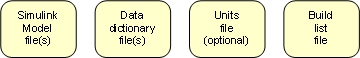
- Simulink model file(s)
One or more Simulink model file which use Simulink and OpenECU (and possibly custom) blocks to detail the functionality of the application. The model files are covered in Section 4.2.2.1, “Model”.
- Data dictionary file(s)
One or more text files or Simulink data dictionary files which detail each of the named block parameters and named signals in the Simulink model. Details include units, range, description, and more. The data dictionary files are covered in Section 4.2.2.2, “Data dictionary files”.
- Units file
An optional text file which lists the allowable units used to describe named parameters and signals in the model. The units file is covered in Section 4.2.2.3, “Units file”.
- Build list file
One MATLAB file which lists the data dictionary files used by the model. The build list file is read when the Simulink model is loaded into Simulink and the workspace is populated with data dictionary information. The build list file is covered in Section 4.2.2.4, “Build list file”.
Note
Simulink Data Dictionaries are supported in R2015a and later.
An OpenECU model can be created by:
creating a new directory to store the model;
changing MATLAB's current path to the newly created directory;
issuing the following command at MATLAB's prompt:
oe_create_model '[model-name]' 'dd' '[dd-name]' 'part' '[part-number]' 'template' 'basic'Where the text
[model-name]is replaced by the name to be given to the model, the text[dd-name]is replaced by the name of the data dictionary and the text[part-number]is replaced by the part number of the target (e.g.,01T-068144-000for the M460-000). The command opens a new Simulink model, creates a basic build list and data dictionary file, adds put_Identification block to configure the ECU.The model parameters are important to the correct working of OpenECU models and are discussed in a little more detail in the following sections.
save the model.
The procedure above uses a default name for the data dictionary and a default version of hardware but these can be specified when creating the model.
oe_create_model('model-name', 'dd', '[dd_name]', 'part', '[part-number]')where [dd_name] is replaced by the name of the data dictionary (e.g., the step1 model from Section 3.3, “Exercise — Step 1” uses a data dictionary named stp) and where [part-number] is replaced by the part-number of the target (see Section 5.1.63, “Model identification (put_Identification)”). For more details, issue this command at MATLAB's command window:
help oe_create_model
The oe_create_model command will not be able
to create a new model when it cannot understand some of the parameters
given to it or if it cannot access the file system (e.g., if
the file cannot be written or the file system is full).
If an error does occur when creating the model, once the problem
that caused the error has been resolved, it is best to remove the
intermediate set of files that the oe_create_model
command generated, before issuing the command a second time.
A data dictionary can be either a text file, or a Simulink proprietary format file with the extension .sldd starting in R2015a. Prior to R2015a only text file based data dictionary files are supported.
A text file based data dictionary file is a simple tab delimited text file format and must contain at minimum: the name, default value and type for calibratables and the name and type only for displayables. When a model is loaded, the data dictionary files are read into MATLAB's workspace to support simulation or building. Optionally, these can be used to generate ASAP2 files at build time. See Section 4.3.4, “Configuration options” for details.
Note that non-ASCII characters appearing in the data dictionary may not be interpreted correctly by the calibration tool reading the resultant ASAP2 files, since different calibration tools use different extended encoding conventions. It is best therefore to stick to ASCII characters within the data dictionary.
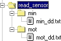
Each data dictionary file is stored in a directory of the same name.
Given the example of the model read_sensor above, then
there would be two directories named min and
mot:

Each data dictionary file stored in each of those directories must be
named data dictionary name_dd.txt.
Given the example of the model read_sensor above, then
there would be two files named min_dd.txt and
mot_dd.txt in the corresponding directories:
Each data dictionary follows a simple format, separated into columns and will look something like:
Name            Value  Units  Type    Accuracy  Min  Max  Description
moi_pressure           kPa    real_T  0.01      20   80   Pressure reading
moi_temperature        degC   real_T  0.01      -40  150  Temperature reading
To help readability, comment lines can be inserted into a data dictionary file.
Comment lines are ignored and start with either a **
or the -- character sequence. For example:
Name            Value  Units  Type    Accuracy  Min  Max  Description
** A comment line
moi_pressure           kPa    real_T  0.01      20   80   Pressure reading

-- Another comment line
moi_temperature        degC   real_T  0.01      -40  150  Temperature reading
Each column has a heading, followed by as many data dictionary entries
as necessary. Each column is separated by a TAB character
and because of this, Excel is a very useful tool for editing the
files (in Excel, save the file as Text (tab delimited) *.txt).
Each column has a use:
Table 4.2. Data dictionary columns
| Column | Description |
|---|---|
| Name | The name of the data dictionary entry. The name must conform to the naming convention detailed in Section 8.2.5, “Naming rules”. |
| Value | The value of a calibration constant, 1d or 2d map. A value should not be created for a Simulink signal. |
| Units | The engineering units for this entry (can be restricted to a set of possibilities with a units file (Section 4.2.2.3, “Units file”)). |
| Description | A description of the data dictionary entry. Must not contain single or double quotes. |
| Type | Any one of int8_T, uint8_T,
int16_T, uint16_T, int32_T
uint32_T, real_T or bool.
The type must match the type assigned to the signal by Simulink. |
| Accuracy | The number of decimal digits to display when viewing the
data dictionary entry with a calibration tool. For instance,
1 shows no digits after the decimal point,
0.01 shows two digits after the decimal point. |
| Min | The minimum expected value for this data dictionary entry. |
| Max | The maximum expected value for this data dictionary entry. |
| Scale | This column is optional. It specifies the amount by which the displayed value will be scaled from the raw value read from the ECU. |
| Offset | This column is optional. It specifies the amount by which the displayed value will be offset from the raw value read from the ECU. |
| Enums | A comma separated list of data dictionary entries which provide the possible values this data dictionary entry can be. This column is optional. |
| Defn | This column is optional. It specifies the file in which the equivalent C variable for the DDE will be defined. Only applicable when using RTW Embedded Coder, the column is ignored for other auto-coders. |
| Decl | This column is optional. It specifies the file in which the equivalent C variable for the DDE will be declared. Only applicable when using RTW Embedded Coder, the column is ignored for other auto-coders. |
| Lookup | Reserved for future use, do not use. |
| Group | Reserved for future use, do not use. |
| Rate | Reserved for future use, do not use. |
An example of how the data dictionary can be used to name model signals, model constants and map look-ups is given below. Each entry follows the naming convention laid out in (Section 8.2.5, “Naming rules”). Explore the OpenECU demos for more examples (Section 3.2, “Installed examples”).
Name           Value               Units  Type    Min Max  Description

** Example of a signal DDE
moi_pressure                       kPa    real_T  20  80   Example of a named signal

** Example of a constant look-up DDE
moic_constant  50                  kPa    real_T  20  80   Example of a calibration constant

** Example of set of a 1D table/map look-up DDEs
moim_1d_map_x  [20 40 80]          kPa    real_T  20  80   Example of a x-axis for a 1d map
moim_1d_map_z  [0  0  1]           state  bool    0   1    Example of a z-data for a 1d map

** Example of set of a 2D table/map look-up DDEs
moim_2d_map_x  [20 40]             kPa    real_T  20  80   Example of a x-axis for a 2d map
moim_2d_map_y  [1  5  10]          sec    real_T  0   25   Example of a y-axis for a 2d map
moim_2d_map_z  [0  1; 4  5; 8  9]  steps  real_T  0   100  Example of a z-data for a 2d map

** Example of set of an array DDE
moiv           [1 2 3 5 8 13]      counts real_T  0   100  Example of an array
Instead of using values to represent discrete states, enumerations
can be used instead. These represent the discrete states using
a textual name rather than a number. For instance, in the following
example, moi_state can have two enumerations:
MOI_RUNNING which represents the value 0 and
MOI_STOPPED which represents the value 1.
It is easier to understand and interpret the enumerations than the
values.
Name         Value  Units  Type    Min  Max  Enums                     Description

moi_state           state  real_T  0    1    MOI_RUNNING, MOI_STOPPED  Example of a st ...

MOI_RUNNING  0      enum   real_T                                      Enumeration for ...
MOI_STOPPED  1      enum   real_T                                      Enumeration for ...
When a model is loaded, each data dictionary entry is checked for errors. A complete list of checks is given in Appendix 8, Data dictionary tool errors. If any errors or warnings are displayed, go back and edit the file to remove the errors.
Note
When a data dictionary is changed OpenECU does not automatically read the file. Instead, the user must read the data dictionaries by running the command:
oe_read_build_list
at MATLAB's prompt.
In R2015a and later, a Simulink based data dictionary file with an extension of .sldd
can be used with OpenECU. This type of data dictionary holds the same information
as a text based data dictionary, only the data is stored in oe.Parameter
and oe.Signal objects in the data dictionary file from within Simulink,
instead of externally in text files. This file can be edited manually from within
Simulink using the Model Explorer interface, or programmatically in Simulink using the
Simulink.data.dictionary class and API.
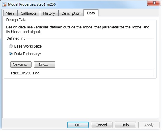
The data dictionary file is specified in the Model Properties dialog box of the model File-> Model Properties-> Model Properties under the Data tab, as shown in the image below.
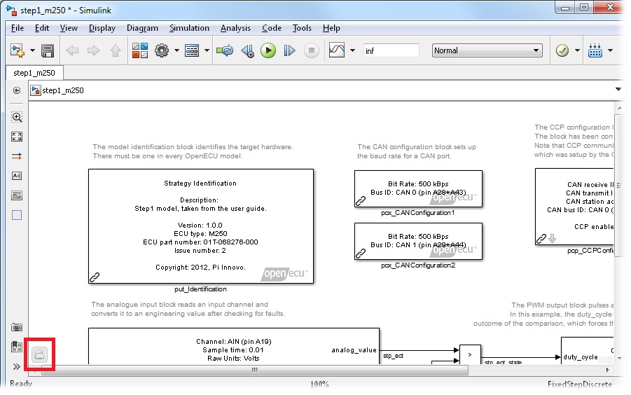
The data dictionary file can be viewed or edited by clicking the icon in the bottom left hand corner of the model once it has been configured to use a data dictionary, as shown below.
The data dictionary file is then edited in Model Explorer Tools-> Model Explorer, as shown below.
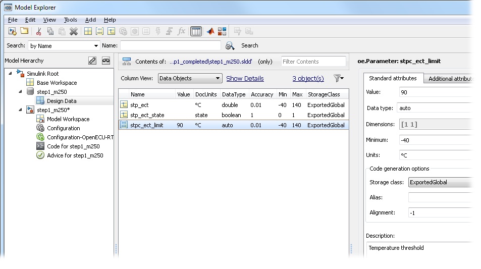
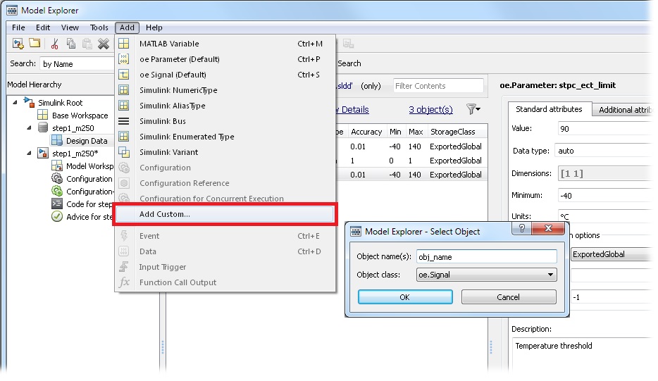
To add a new oe.Parameter or oe.Signal object to the data dictionary
select Add-> Add Custom... from the Model Explorer menu, and in the dialog box, specify
the name of the variable and the class of the variable (either oe.Parameter or
oe.Signal), as shown below.
OpenECU uses the following properties for each signal object:
Table 4.3. Simulink data dictionary object properties
oe.Parameter property | oe.Signal property | Text based column equivalent | Description |
|---|---|---|---|
| Object name | Object name | Name | The name of the object in the data dictionary. The name does not need to conform to the naming convention if the model is configured to use oe objects, and to disable the naming convention. |
| name.Value | Value | The value of a paramter constant, 1d or 2d map.
Only valid for oe.Parameter objects. | |
| name.DocUnits | name.DocUnits | Units | The engineering units for this entry. Units file is not supported. |
| name.Description | name.Description | Description | A description of the data dictionary entry. |
| name.DataType | name.DataType | Type | A Simulink supported data type. |
| name.Accuracy | name.Accuracy | Accuracy | The number of decimal digits to display when viewing the
data dictionary entry with a calibration tool. For instance,
1 shows no digits after the decimal point,
0.01 shows two digits after the decimal point. |
| name.Scale | name.Scale | Scale | The amount by which the displayed value will be scaled from the raw value read from the ECU. |
| name.Offset | name.Offset | Offset | The amount by which the displayed value will be offset from the raw value read from the ECU. |
| name.Min | name.Min | Min | The minimum expected value for this data dictionary entry. |
| name.Max | name.Max | Max | The maximum expected value for this data dictionary entry. |
| name.Enums | name.Enums | Enums | A comma separated list of oe.Parameter objects which provide the possible values this data dictionary entry can be. This property can be left blank. |
|
name .CoderInfo .CustomAttributes .DefinitionFile |
name .CoderInfo .CustomAttributes .DefinitionFile | Defn | This property is optional. It specifies the file in which the equivalent C variable for the DDE will be defined. Only applicable when using Embedded Coder, the property is ignored for other auto-coders. |
|
name .CoderInfo .CustomAttributes .HeaderFile |
name .CoderInfo .CustomAttributes .HeaderFile | Decl | This property is optional. It specifies the file in which the equivalent C variable for the DDE will be declared. Only applicable when using Embedded Coder, the property is ignored for other auto-coders. |
With a Simulink data dictionary, in order to make each variable available in a calibration tool, the variable must have certain properties set in order to control the storage of that variable. The properties must be set differently depending on the auto-coder used (see Section 4.3.2, “Auto-coders” for more details about auto-coders), and the desired type and scope of the variable.
The following table details the desired variable type in the model or calibration tool, and the data object and properties required for each auto-coder which must be set to generate that variable in the model and make available in the calibration tool:
Table 4.4. Simulink data dictionary object storage classes
| Variable type | Auto coder | Data object | Properties |
|---|---|---|---|
| Constant scalars | any | oe.Parameter |
name .CoderInfo .StorageClass = 'Auto' |
|
Calibration scalars Calibration maps (1d or 2d), or Arrays | GRT RTMODEL | oe.Parameter |
name .CoderInfo .StorageClass = 'ExportedGlobal' |
| Displayable signals | GRT RTMODEL | oe.Signal |
name .CoderInfo .StorageClass = 'ExportedGlobal' |
|
Calibration scalars Calibration maps (1d or 2d), or Arrays | EC | oe.Parameter |
name .CoderInfo .StorageClass = 'Custom' name .CoderInfo .CustomStorageClass = 'Global' name .CoderInfo .CustomAttributes .MemorySection = 'Calibration' |
| Displayable signals | EC | oe.Signal |
name .CoderInfo .StorageClass = 'Custom' name .CoderInfo .CustomStorageClass = 'Global' name .CoderInfo .CustomAttributes .MemorySection = 'Displayable' |
Note
In the Model Explorer interface, the name.CoderInfo.StorageClass, and name.CoderInfo.CustomStorageClass, properties are normally merged into the same drop down selection field. The 'Global (Custom)' selection will select both name.CoderInfo.StorageClass = 'Custom' and name.CoderInfo.CustomStorageClass = 'Global' at the same time.
Note
The oe.Signal and oe.Parameter object classes are
derived from the native Simulink.Signal and Simulink.Parameter
classes and are designed to better integrate with OpenECU projects. It is highly recommended
to use the OpenECU specific object whenever possible, as the Simulink native object classes
are not officially supported by OpenECU.
A model configured to use a text based data dictionary can be automatically converted to use a Simulink data dictionary with all of the existing data dictionary entries imported into the .sldd file by calling the following command:
oe_config_using_sim_dd
at MATLAB's command prompt.
By default, the script will convert the currently active model, using the data dictionary file name
model-name.sldd. If the data dictionary file already exists
it can be overwritten with additional parameters. See details at oe_config_using_sim_dd.
In addition to the previously mentioned data dictionary variables, additional data can also be stored in a Simulink data dictionary file, such as Simulink.Bus objects, Simulink enum type definitions, Configuration Sets, and other built-in Simulink types. Please refer to the Simulink documentation for further details on the data that can be stored in a Simulink data dictionary file.
A units file is a simple text file format, where each line represents a single allowable unit. When a model is loaded, the data dictionary entries and unit entries are read, and any data dictionary that does not use one of the unit entries raises a warning.
A units file is only supported with text based data dictionaries.
A units file is stored in the same directory as the model.
A units file for a model must have the file-name
model-name_units.txt where
model-name is replaced by the name of the model. An
example units file for a model named read_sensor
would be named read_sensor_units.txt and might look like:
degC
kPa
In this example, only two units: degC or kPa, can be used for each data dictionary entry.
To help readability, comment lines can be inserted into the units file.
Comment lines are ignored and start with either a **
or the -- character sequence. For example:
** Allowable units for the read_sensor model
degC
kPa
A build list file is a simple m-script that specifies what the data dictionary files are called. When a model is loaded, the build list is read to determine which data dictionaries are to be read into MATLAB's workspace.
A build list file for a model must have the file-name
model-name_bl.m where
model-name is replaced by the name of the model. An
example build list file for a model named read_sensor
would be named read_sensor_bl.m and would like very
similar to:
feature_list = [{'min',
                 'mot'}];
In this example, the build list defines two data dictionary files, named
min and mot. Further data dictionary
files can be added by extending the vector feature_list.
It is important to use three characters for each data dictionary name.
If a model is configured to use a Simulink data dictionary, the build list file will only list the feature directories which are to be added to the MATLAB path. The data dictionary files are specified within the model properties.