The update model stage adds or adjusts the functionality of the model. It's important to keep the data dictionary files up to date with changes to the model. It's easy to leave changes to the data dictionary until later, but that often leads to multiple build and update cycles as missing data dictionary elements are found during the testing stage.
Before Simulink starts to simulate a model on the host PC, or builds a model
to run on an ECU, Simulink attempts to solve the model and applies consistency
checks during the solving. This process is called a diagram update.
A diagram update can be performed at any point by pressing CTRL+D
in a model window, or by selecting the Edit -> Update diagram.
Note
It is useful to periodically update the model diagram to check that everything has been accounted for. However, Simulink does not provide a mechanism for OpenECU to ensure the text based data dictionary files have been incorporated into the model. Therefore, if the data dictionary files have been updated, prior to a diagram update, the user must issue the following command:
oe_read_build_list
at MATLAB's command prompt to ask OpenECU to read the data dictionary files.
If you are unfamiliar with Simulink models then note that it is worth the extra effort up front to partition your application into smaller blocks of functionality. Each block of functionality is placed in a subsystem. With complex areas of functionality, breaking those areas of functionality into less complex interrelated blocks, each within a subsystem, can help readability.
Simulink provides a Model Explorer tool which makes it easy to navigate between parts of the model based on the hierarchy of the subsystems. And OpenECU can incorporate the model hierarchy into the files used to communicate with the ECU while the ECU is running the model.
For instance, at a top level, a useful pattern to follow breaks the model into an input, output and application subsystem.
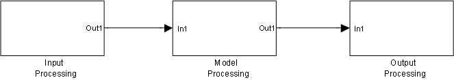
- Input processing
The input subsystem reads sensor and actuator feedback signals and decodes communication messages, transforming raw sensor information into engineering units (possibly applying filters and other validation techniques to ensure the input data is usable). The input subsystem can be broken down into further subsystems, perhaps one to read the raw sensor information, one to process into engineering units, and one to validate the inputs (perhaps against other sensor inputs or against a plant model of the system under control).
- Application processing
The model subsystem processes the input subsystem data, determining how the system it is controlling should react. The model subsystem would be further broken down into smaller subsystems, each performing a small portion of the overall functionality. The model subsystem creates the data in engineering units necessary to drive the output subsystem.
- Output processing
The output subsystem drives the actuators connected to the ECU to achieve the demands of the model subsystem.
By breaking the model into these subsystems, the input and output subsystems can easily be replaced when targeting another ECU. For instance, when moving to a more powerful ECU because the application has grown, or when moving to a less powerful ECU because the production needs for the prototyped application mean a cheaper ECU can be used.