Before we can run the model simulation, each Simulink block requires a number of parameters that define initial conditions, sample rates, and various other dynamic properties of the model.
Block parameters are set by double-clicking on the block and entering appropriate values in the various parameter fields that are displayed. Some parameters may only take on certain values, in which case the text field is replaced by a drop-down list, from which you can select the appropriate value.
The parameters dialogue box for the Model Identification looks like this:
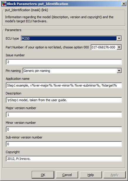
Set the block mask parameters as the figure shows. A full description of the block mask parameters is given later on Section 5.1.63, “Model identification (put_Identification)”, but a summary of the items and their meaning is given here for this example.
Table 3.1. Step1 - model identification block parameters
| Parameter | Description | Set to |
|---|---|---|
| ECU type | Identifies the name of the type of ECU. | (already set by running the oe_create_model
command) |
| Part Number | Identifies the hardware part number of the ECU. | (already set by running the oe_create_model
command) |
| Issue number | Identifies the issue number of the ECU. | (already set by running the oe_create_model
command) |
| Pin naming | Specifies the naming given to each blocks channel or pin selection. | Generic pin naming |
| Application name | Specifies a name for the application/model. Although this parameter has no functional effect on the model, it is used when generating the model ASAP2 file and can be retrieved over CCP using the EXCHANGE-ID message. | Step1 example, v%ver-major%.%ver-minor%.%ver-subminor%, %target% |
| Description | Specifies a description of the model (this parameter has no functional effect on the model). | Step1 model from OpenECU manual. |
| Major version number | Specifies the major version number of the model. This value can be read over CCP by a ASAP2 compliant tool and is useful to determine if the target hardware is running the correct version of the model. | 1 |
| Minor version number | Specifies the minor version number of the model. This value can be read over CCP by a ASAP2 compliant tool and is useful to determine if the target hardware is running the correct version of the model. | 0 |
| Sub-minor version number | Specifies the minor version number of the model. This value can be read over CCP by a ASAP2 compliant tool and is useful to determine if the target hardware is running the correct version of the model. | 0 |
| Copyright | Specifies a copyright for the model (this parameter has no functional effect on the model). | 2012. |
Note
It is essential to include a put_Identification block in all OpenECU top level models. If this block is not present, the model will not work as documented.
The parameters dialogue box for the CAN Configuration looks like this:
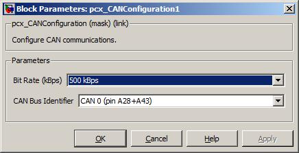
Set the block mask parameters as the figure shows. A full description of the block mask parameters is given later in Section 5.1.13, “CAN configuration (pcx_CANConfiguration)”, but a summary of the items and their meaning is given here for this example.
Table 3.2. Step1 - CAN configuration block parameters
| Parameter | Description | Set to |
|---|---|---|
| Bit rate | The bit rate (or baud rate) of the CAN bus. | 500 kBps |
| CAN bus identifier | Which CAN bus the configuration applies to. | CAN 0 |
The parameters dialogue box for the CCP Configuration looks like this:
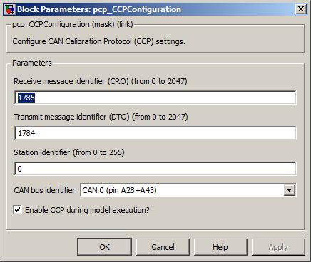
Set the block mask parameters as the figure shows. A full description of the block mask parameters is given later in Section 5.1.19, “CCP configuration (pcp_CCPConfiguration)”, but a summary of the items and their meaning is given here for this example.
Table 3.3. Step1 - CCP configuration block parameters
| Parameter | Description | Set to |
|---|---|---|
| Receive message identifier | A unique standard CAN message identifier for CCP CRO messages. This is the CAN identifier used to talk to the OpenECU device. For this example, we'll use the default value. | 1785 |
| Transmit message identifier | A unique standard CAN message identifier for CCP DTO messages. This is the CAN identifier used to talk from the OpenECU device. For this example, we'll use the default value. | 1784 |
| Station address | The station address for CCP sessions. OpenECU will only communicate using CCP if a session is opened using this station address. For this example, we'll use the default value. | 0 |
| CAN bus identifier | Which CAN bus CCP communications will occur on. Previously, we configured CAN 0 to run at 500 kBps, so we'll use CAN 0 for CCP communications. | CAN 0 |
| Enable CCP during model execution? | Whether to communicate using CCP when the model is
executing or whether it will only communicate using CCP when
programming. We will want to view signals
stp_ect and stp_ect_state when
the model is running (and possibly change calibrations as well) so
this should be ticked. | (tick) |
| Use CRO extended ID? (29 bit) | As the model has been configured with 11 bit CAN identifiers for CCP i.e., CRO set to 1785, so this should be unticked. | (untick) |
| Use DTO extended ID? (29 bit) | As the model has been configured with 11 bit CAN identifiers for CCP i.e., DTO set to 1784, so this should be unticked. | (untick) |
The parameters dialogue box for the Analogue Input looks like this:
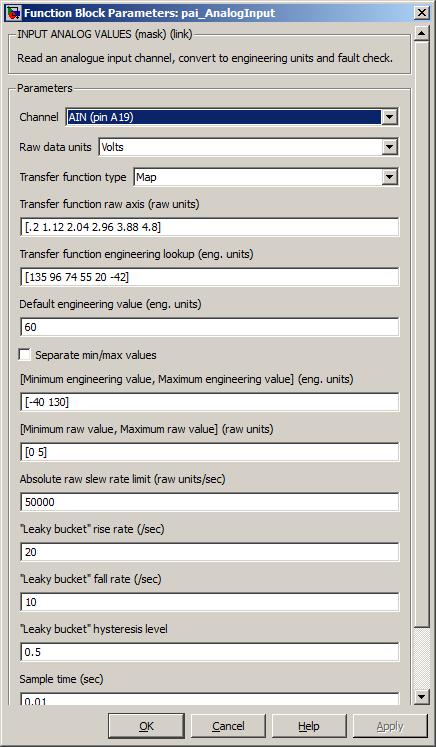
Set the block mask parameters as the figure shows. A full description of the block mask parameters is given later on Section 5.1.6, “Analogue input — processed (pai_AnalogInput)”, but a summary of the items and their meaning is given here for this example.
Table 3.4. Step1 - analogue input block parameters
| Parameter | Description | Set to |
|---|---|---|
| Channel | Which channel will be used for the raw input from the temperature sensor. | AIN (pin A19) for M220, AIN (pin A19) for M250, AIN (pin A28) for M460 and M461, or AIN (pin Y31) for M670 |
| Raw data units | Units in which the raw analogue values for this block are interpreted. | Volts |
| Transfer function type | The type of tranfer function to use when converting from raw values to engineering values. In this example we set it to use an interpolating lookup map. | Map |
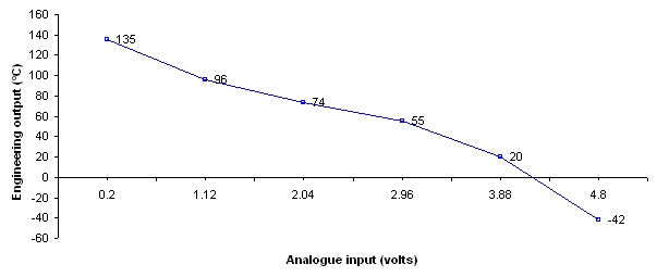
| Transfer function raw axis | The values of this and the engineering lookup define a
transfer function that is characteristic of the particular
temperature sensor we're using. The raw axis defines some
arbitrary inputs to the sensor, and the eng lookup defines the
corresponding output behaviour. Note that the number here represents
the analogue pin voltage because Raw data units is
set to Volts. | [.2 1.12 2.04 2.96 3.88 4.8] |
| Transfer function engineering lookup | (see above) | [135 96 74 55 20 -42] |
| Default engineering value | The default starting value for the parameter (in °C). | 60 |
| Separate min/max values | Option to separate the Minimum/maximum engineering value and Minimum/maximum raw value into four separate parameters. Not used in this example. | unchecked |
| Minimum/maximum engineering value | The minimum and maximum values that are to be expected for this value (in °C). | [-40 130] |
| Minimum/maximum raw value | The minimum and maximum raw values that are expected at the input to
the block's transfer function. These units correspond to the setting of Raw data units,
hence the range for Volts. | [0 5] |
| Absolute raw slew rate limit | The maximum rate at which the signal is expected to rise or fall. By setting this to a large number, we can ensure that the block will never detect a slew rate limit fault. | 10000000 |
| Leaky bucket rise rate | This is the threshold rate above which incoming fault data will trigger a permanent fault. Setup for this example so that a fault is never detected. | 20 |
| Leaky bucket fall rate | This is the threshold rate below which incoming fault data will cease to trigger a fault indication. Setup for this example so that a fault is never detected. | 10 |
| Leaky bucket hysteresis | This is the amount of hysteresis in the leaky bucket fault filter system. Setup for this example so that a fault is never detected. | 0.5 |
| Sample time | The time (in seconds) between samples, i.e., how often this block will be integrated. | 0.01 |
The transfer function allows for non-linear conversion but must adhere to the same restrictions as the put_Calmap1d block (e.g., regarding axis monotonicity). The transfer function from the analogue input block data above in Figure 3.4, “Analogue input transfer function”.
The parameters dialogue box for the PWM Output looks like this:
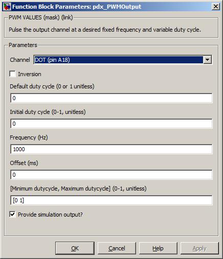
Set the block mask parameters as the figure shows. A full description of the block mask parameters is given later on Section 5.1.84, “PWM output — fixed frequency (pdx_PWMOutput)”, but a summary of the items and their meaning is given here for this example.
Table 3.5. Step1 - PWM output block parameters
| Parameter | Description | Set to |
|---|---|---|
| Channel | Which channel will be used for the PWM output signal. | DOT (pin A37) for M220, DOT (pin A18) for M250, DOT (pin A15) for M460 and M461, or DOT (pin Y29) for M670 |
| Inversion | Whether the logical function of the block will be inverted (ticked) or not (unticked). | (unticked) |
| Default duty cycle | The default output duty cycle used when a fault is specified. In this example, the fault inport is always force to zero, so this condition never arises. | 1 |
| Initial duty cycle | The initial duty cycle before the model starts to run. | |
| Frequency | The frequency of the signal. Although this example always uses a 0% or 100% duty cycle, i.e., always on or off, the frequency must still be specified. | 1000 |
| Offset | The offset of the signal relative to other PWM signals of the same frequency. An advanced feature that can be ignored in this case. | 0 |
| Minimum/maximum duty cycle | The minimum and maximum duty cycle range for this input. | [0 1] |
| Sample time | The time (in seconds) between block iterations. | 0.01 |
This example uses a PWM output to drive an output either fully on (100% duty-cycle) or fully off (0% duty-cycle). A digital output block Section 5.1.43, “Digital output (pdx_DigitalOutput)” could have been used instead and is the more logical choice for this example. However, the example uses a PWM output block to show that different outputs can be used in equivalent ways.
Your model should now look like Figure 3.5, “Configured quick start model”.
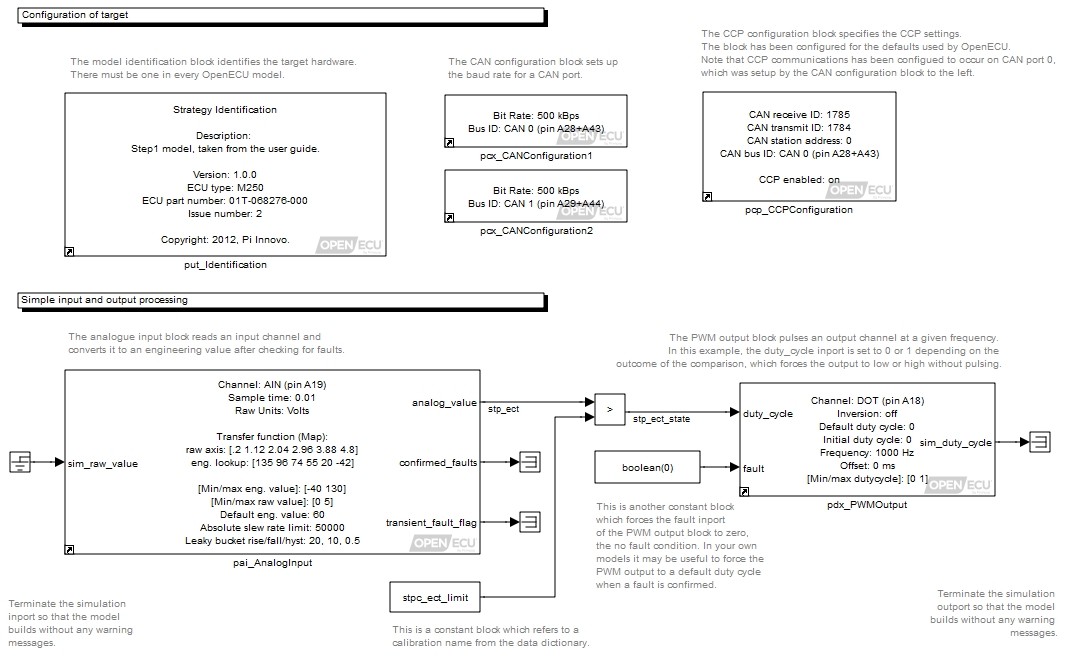
So far, you have populated the model with a number of Simulink and OpenECU blocks, defined some behaviour by linking the blocks together to interact and now need to provide the framework around the model to allow it to be built and run on an OpenECU device.