While designing and running the model, and later testing it with the calibration tool, it is very useful to be able to interactively display and set the values that are present on parts of the model. You can do this by assigning names to a signal or input at the modelling stage, and then display or set the value associated with that variable as the model simulation is running.
Variables must be named according to a system described in full in Section 8.2.5, “Naming rules”. This system helps you to identify what type of information the variable holds, and where it is initialised and used — very helpful in tracking down any design faults. Note that calibratable variables of this type can only be changed on-the-fly with the development ECU (i.e. not with the fleet ECU, which requires programming of its memory to change any variable values).
We will use two signal variables in our design:
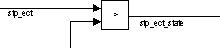
stp_ectThis is the value of the temperature that is output from the Analogue Input block, representing the temperature of the engine in degrees Centigrade;
stp_ect_stateThis is the result of the relational operator that calculates whether the engine temperature is greater than the threshold temperature. It is 1 when the threshold is breached, and 0 otherwise.
Label the signals on either side of the Relational Operator block as follows:
To assign a name to a signal:
double-click on the appropriate signal and a text box will open beneath it;
type in the variable name, then click outside the box to complete.
We will also use a variable so that we can change the threshold temperature while the simulation is running. Note that calibratable variables of this type can only be changed on-the-fly in the ECU with the development ECU (i.e. not with the fleet ECU, which requires programming of its memory to change any variable values).
The variable to set up is stpc_ect_limit
— the threshold temperature (in degrees Centigrade) which
defines the temperature above which our warning light will switch on.
To set this variable:
double-click on the Constant block that leads into the lower of the two Relational Operator inputs. A dialogue box appears.
click in the Value box, and instead of entering a numerical value, enter the variable name
stpc_ect_limit. This now references a MATLAB workspace variable (which we will create further on).
You will also need to set a single constant used in the model:
double-click the Constant block that leads into the fault_value inport of the PWM Output block. A dialogue box appears.
click in the Value box and enter
boolean(0). This instructs the PWM Output block that there are no faults in the system.