Before any engineering project reaches the design and modelling stage, several detailed planning stages should be carried out to define suitable functional requirements and specifications. Once you have a detailed target for your design, you can then start to create and model it. Many engineers prefer to use pen and paper, but it's equally acceptable these days to develop your design directly in modelling packages such as MATLAB and Simulink.
In this example, we have designed and partially modelled the system for you — you need only finish the modelling process as described below.
To create the model:
Create an empty model
Create an empty directory somewhere to store the step1 model. Start up MATLAB/Simulink and change to that directory. Read off the part and issue numbers from the label on your ECU. The part number is the text string beginning '01T-'. The issue number appears immediately afterwards: it is the number before the 'm'. For example, the label on an M250 module might read:
Part No. 01T-068276-000 2m1In this example, the part number is '01T-068276-000' and the issue number is 2. Note that some part do not include the last three characters. Issue the following command at MATLAB's command prompt:
oe_create_model('step1',
                'dd',       'stp',
                'template', 'minimal',
                'part',     '01T-068276-000',
                'issue',    2)
This will create an OpenECU model named 'step1' with appropriate model settings as well as a basic build list and a data dictionary using the prefix 'stp'. Replace the text string '01T-068276-000' with the part number for your ECU, and the number 2 with the issue number for your ECU. For more information issue the following command at MATLAB's command prompt:
help oe_create_model
If your ECU part number does not have the final three characters, just enter what is there, for example:
oe_create_model('step1',
                'dd',       'stp',
                'template', 'minimal',
                'part',     '01T-068276',
                'issue',    2)
A new model with 'minimal' template has opened containing a single block called put_Identification and while the model was opening, some additional text was printed to the MATLAB command window.
Obtaining workspace data from each feature data dictionary...
Workspace variables loaded
Populate the model
Open the Library browser window and select the blocks that you will use in your model. These blocks are:
from the Source list: Ground;
from the Sink list: Terminator;
from the Math list: Constant, Relational Operator;
from the Pi OpenECU, Input Drivers list: Analogue Input;
from the Pi OpenECU, Output Drivers list: PWM Output;
from the Pi OpenECU, CAN Drivers list: CAN Configuration;
from the Pi OpenECU, Utilities list: Identification, CCP Configuration.
Change the operation of the Relational Operator block to greater-than (>).
Connect the blocks
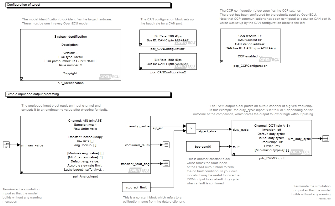
Connect the blocks together as shown in Figure 3.3, “Connected quick start model” (note that the text in gray is commentary for this manual and need not be entered in your model):
Note
The analogue input needs to be connected to ground and the PWM output needs to be terminated to prevent Simulink from reporting an Unconnected Input error when the simulation is run. The grounded inputs and outputs to and from your system only provide simulated inputs and outputs when running in Simulink. When running on the target ECU, these grounded inputs and outputs are ignored and the blocks read sensors and drive actuators.
Save the model
Save the model. You now have a partially complete graphical model of your design.
We still need to incorporate some design variables and parameters in some of the blocks and interconnecting wires or signals in our model. By naming things, we can use the calibration tool to set or inspect their values when we test the working system running on the ECU.