Read an analogue input channel, convert to engineering units and fault check.
None (Main library). (See Section 2.3, “Licensed Features”.)
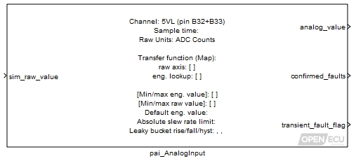
This block reads a physical analogue channel identified to obtain a raw input value when run on target hardware. When run in simulation, the block instead takes the value on its input as its raw value.
Depending on the block's configuration, a raw value is either a measure of the voltage on the processor's analog-input pin or the number obtained from the analogue-to-digital converter in the ECU device scaled as if it had 10-bit resolution, such that 0 indicates the reference ground (usually 0 volts) and 1023 indicates the upper reference voltage (usually 5 volts).
Note
The worst case conversion time for all analogue-to-digital values is ~500μs. Thus, when the software asks for an analogue-to-digital conversion, the analogue-to-digital value may be up to 500μs old.
When the Transfer function type is set to “Map”, the block converts the raw value into an engineering value through a 1-d table look-up. When set to “Linear”, the block uses a linear equation with a specified scale and offset to convert the raw value to engineering value.
An engineering value is the value which takes the physical units appropriate for a particular input device, e.g. kPa for a pressure sensor. This is obtained from the raw value through some appropriate transformation. As the user specifies the transformation in the mask, it is the responsibility of the user to choose appropriate and consistent units.
This block provides range and slew fault checking for analogue inputs. Range checking is performed for raw values as well as engineering values.
When any range or slew error is detected, the block initially yields the last good value held. If the leaky bucket confirms a fault however, the default value is output instead.
Filtering of faults is achieved using a leaky bucket algorithm. A leaky bucket integrator is used to decide when an input is confirmed as faulty as a function of its current state, which may be only transiently in error. Here the bucket always has a total volume or depth of unity (1.0). When the input is deemed to be in error (e.g. out of range), water is poured into the bucket at some rise rate. At all times water flows out of a leak in the bottom of the bucket with some fall rate until it is empty. If the bucket should ever fill to the brim by reaching a depth greater than or equal to 1.0, the input is confirmed as faulty. Should the bucket subsequently empty to below its hysteresis depth, it is no longer confirmed as faulty.
Engineering value of the analogue input conversion (see Transfer function for the conversion), possibly clamped to the default value if any faults are active.
Value type: Real Calibratable: No A vector of 5 outputs. if any are set, a confirmed fault condition is set.
Element Description Range 1 Raw output is below lower range limit. 0 or 1 2 Raw output is above upper range limit. 0 or 1 3 Slew rate fault for raw value. 0 or 1 4 Engineering output is below lower range limit. 0 or 1 5 Engineering output is above upper range limit. 0 or 1 Value type: Boolean Calibratable: No Whether the input value is currently faulty (e.g. out of range). A scalar flag.
Range: 0 or 1
Value type: Boolean Calibratable: No
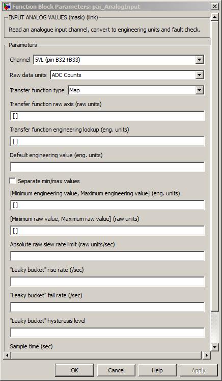
The channel pin for this analogue input.
Value type: List Calibratable: No The units in which the raw analogue input data is read. Either 'ADC Counts' (default) or 'Volts'.
Value type: List Calibratable: No The type of transfer function to use when converting from raw units to engineering units. Either 'Map' (default) or 'Linear'.
This enables or disables the following parameters:
Parameter Map Linear Transfer function raw axis Enabled Disabled Transfer function engineering look-up Enabled Disabled Transfer function scale Disabled Enabled Transfer function x offset Disabled Enabled Transfer function z offset Disabled Enabled Value type: List Calibratable: No Vector of breakpoints for z = f(x) raw value to engineering value look-up when Transfer function type is set to Map.
Range: [-1023, 1023] A/D counts, [-5, 5] Volts
Value type: Real Calibratable: Yes, offline and online Transfer function engineering look-up
Vector of data points for engineering value look-up when Transfer function type is set to Map.
Value type: Real Calibratable: Yes, offline and online Scale of transfer function when Transfer function type is set to Linear. 'm' for z = m*(x + a) + b
Value type: Real Calibratable: Yes, offline and online Offset of transfer function when Transfer function type is set to Linear. 'a' for z = m*(x + a) + b
Range: [-1023, 1023] A/D counts, [-5, 5] Volts
Value type: Real Calibratable: Yes, offline and online Offset of transfer function when Transfer function type is set to Linear. 'b' for z = m*(x + a) + b
Value type: Real Calibratable: Yes, offline and online Engineering value to be output if a fault condition is confirmed for this input.
Value type: Real Calibratable: Yes, offline and online Tick to separate min and max values into separate values, or combine into a vector.
This is accomplished by enabling or disabling the following parameters:
Parameter Unchecked Checked Minimum engineering value, Maximum engineering value Enabled Disabled Minimum raw value, Maximum raw value Enabled Disabled Minimum engineering value Disabled Enabled Maximum engineering value Disabled Enabled Minimum raw value Disabled Enabled Maximum raw value Disabled Enabled Value type: Boolean Calibratable: No Minimum engineering value, Maximum engineering value
Vector of minimum and maximum permissible engineering values before input considered faulty when Separate min/max values? is unchecked.
Value type: Real Calibratable: Yes, offline and online Minimum raw value, Maximum raw value
Vector of minimum and maximum permissible raw values before input considered faulty when Separate min/max values? is unchecked.
Range: [-1023, 1023] A/D counts, [-5, 5] Volts
Value type: Integer Calibratable: Yes, offline and online Minimum permissible engineering values before input considered faulty when Separate min/max values? is checked.
Value type: Real Calibratable: Yes, offline and online Maximum permissible engineering values before input considered faulty when Separate min/max values? is checked.
Value type: Real Calibratable: Yes, offline and online Minimum permissible raw values before input considered faulty when Separate min/max values? is checked.
Range: [-1023, 1023] A/D counts, [-5, 5] Volts
Value type: Integer Calibratable: Yes, offline and online Maximum permissible raw values before input considered faulty when Separate min/max values? is checked.
Range: [-1023, 1023] A/D counts, [-5, 5] Volts
Value type: Integer Calibratable: Yes, offline and online Maximum absolute rate of change of input calculated over one model iteration before input considered faulty.
Range: [-inf, inf] A/D counts/sec, [-inf, inf] Volts/sec,
Value type: Real Calibratable: Yes, offline and online Rate at which leaky bucket is filled when input is faulty in some respect.
Range: [0, 1000] /sec
Value type: Integer Calibratable: Yes, offline and online Rate at which leaky bucket is emptied if it is not already empty.
Range: [0, 1000] /sec
Value type: Integer Calibratable: Yes, offline and online Level below which bucket depth must fall before fault is no longer considered faulty. If set to a negative value, fault remains latched. As a special case, if the hysteresis depth is set negative, should the input ever reach a confirmed fault state it remains "latched" there until the ECU device is powered down.
Range: [-1, 1] unitless
Value type: Real Calibratable: Yes, offline and online The periodicity of the block execution.
Range: [0.001, 3600] seconds
Value type: Real Calibratable: No Tick to enable inport sim_raw_value.
Value type: Boolean Calibratable: No