Monitor the response of a digital output.
None (Main library). (See Section 2.3, “Licensed Features”.)
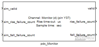
This block allows an application to determine whether or not the state of a digital output has changed as requested within the expected response time. It works by recording the time at which the output function requests a change of state, and then reading the actual state observed on the feedback input at a specific time later. If the actual state does not match the expected state, then a failure is noted. Independent counts of failures to fall and failures to rise are maintained and made available to the application via the outputs from this block.
The block is only available for certain low-side outputs and there are important differences between the falling edge and rising edge cases.
Falling edge: When a low-side output is activated, it is connected to ground within the ECU, and the potential on the pin should drop rapidly to ground potential. Under normal conditions, the time for the potential to fall is largely independent of the load on the pin. Failure of the potential to drop within the expected time indicates a low resistance path to a higher potential on the pin. This will result in a large current draw, causing the output device to get hot and turn off. If the platform software detects that the monitor feedback has not gone low within the expected time, it deactivates the output. The time threshold for the output to go low is hard-coded within the platform software. (See the technical specification of the target ECU for details.) The application can re-enable any disabled outputs using the pss_OvercurTripReset block.
Rising edge: When a low-side output is de-activated, it is disconnected within the ECU, and the potential on the pin should move in the direction of the high-side potential. How fast it does so will depend on the resistance between the pin and the high-side potential, i.e. the resistance of the load. Therefore the time threshold must be specified by the application via the Rise time-out mask parameter of this block. If the potential fails to rise within the expected time, this may indicate an open circuit on the pin, or a short-circuit to ground. Advice on what thresholds to set for different loads is given in the technical specification of the target ECU. The platform software takes no independent action in the case of such a fault being detected beyond reporting the fault count to the application.
Support for this block is restricted to certain types of output. Currently only spark outputs (using the pan_Spark block) and PWM outputs (using the pdx_PWMOutput or pdx_PWMVariableFrequencyOutput blocks) support monitoring (and only on those channels that have the necessary internal feedback signals). If the block is used with some other function on the corresponding output channel, then the valid outport will return 0 (FALSE).
Note that output monitoring will occur on those channels that support it, where possible, regardless of whether or not the application includes a pdx_Monitor block. This means that outputs will be disabled if the corresponding monitor channels fail to go low within the expected time. The only case where such intervention will not take place is if the output function used does not support monitoring.
Only used under simulation. Under simulation, the value of this inport is passed through to the valid outport.
Range: 0 or 1
Value type: Boolean Calibratable: No Only used under simulation. Under simulation, the value of this inport is passed through to the rise_failure_count outport.
Range: [0, 16777215]
Value type: Integer Calibratable: No Only used under simulation. Under simulation, the value of this inport is passed through to the fall_failure_count outport.
Range: [0, 16777215]
Value type: Integer Calibratable: No
Set to 0 when there is a configuration error, most probably due to an output function being used on this channel that does not support monitoring.
Range: 0 or 1
Value type: Boolean Calibratable: No A count of the number of times that the output state did not go high within the time specified by the Rise time-out mask parameter, since the ECU was powered on or reset.
Range: [0, 16777215]
Value type: Integer Calibratable: No A count of the number of times that the output state did not go low within the allowed time, since the ECU was powered on or reset.
Range: [0, 16777215]
Value type: Integer Calibratable: No
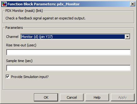
The channel pin to monitor.
Value type: List Calibratable: No The time within which the potential on the output pin is expected to go high after the output is deactivated.
Range: [0, 2000000] microseconds
Value type: Real Calibratable: Yes, offline and online The periodicity of the block execution.
Range: [0.001, 3600] seconds
Value type: Real Calibratable: No Tick to enable simulation inports sim_valid, sim_rise_failure_count and sim_fall_failure_count.
Value type: Boolean Calibratable: No