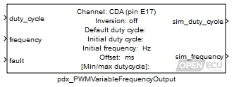
Pulse the output channel pin at a variable frequency and duty cycle.
None (Main library). (See Section 2.3, “Licensed Features”.)
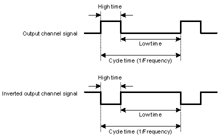
The PWM output block causes the channel output pin to oscillate at a desired frequency and duty cycle. A duty cycle is the High time divided by the Cycle time.
This block calculates the output duty cycle as:
output duty cycle = Minimum duty cycle + (Maximum duty cycle - Minimum duty cycle) * duty_cycle
If the Minimum duty cycle is 0 and the inport duty_cycle is 0, the output channel state is set low and does not oscillate. When the Maximum duty cycle is 1 and the inport Duty_cycle is 1, the output channel state is set high and does not oscillate.
The block supports 0% and 100% duty cycles, where the output signal no longer pulses. A 0% duty cycle is defined as High time equals zero and 100% duty cycle is defined as Low time equals zero.
The channel output pin state can be inverted in order to achieve the desired logical output state.
If the inport fault input is nonzero, then the output is set to the default duty cycle mask parameter (the default duty cycle is never inverted).
Ratio of the high time to the signal cycle time.
Range: [0, 1] duty-cycle
Value type: Real Frequency of the signal.
Range: [0.5, 10000] Hz
Value type: Real Place a 1 here to force the block to use the default frequency and duty cycle for the output, 0 otherwise.
Range: 0 or 1
Value type: Real
Only used in simulation. this outport is set to the processed duty cycle (i.e., duty_cycle or Initial duty cycle).
Value type: Real Only used in simulation. This outport is set to the processed frequency.
Value type: Real
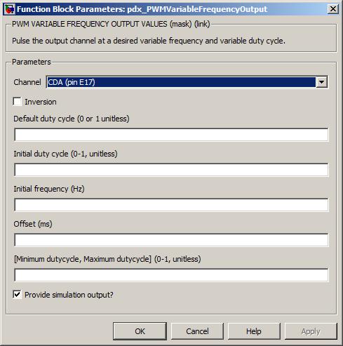
The channel pin for this pwm output.
Value type: List Calibratable: No Inverts the mapping of the input value to the channel pin. If inversion is set to 1 then a logical NOT operation is applied to the output state.
Value type: Boolean Calibratable: No This is the duty cycle of the channel when inport fault is set. The duty cycle is mapped directly to the output channel and is not inverted by parameter Inversion.
Range: [0, 1] duty-cycle
Value type: Real Calibratable: Yes, offline and online The duty cycle of the channel signal before the block has first been executed. This duty cycle is inverted if the mask parameter Inversion is set to 1.
Range: [0, 1] duty-cycle
Value type: Real Calibratable: Yes, offline The frequency of the PWM signal before the block first iterates.
Range: [0.5, 10000] Hz
Value type: Real Calibratable: Yes, offline The desired phase offset, in milliseconds, of the PWM output, relative to other PWM output channels that have been configured with the same frequency.
Range: Target dependent
Target Range M110 Not supported M220 Not supported M221 Not supported M250 [0, 2000] ms M460 [0, 2000] ms M461 Not supported M670 Not supported Value type: Real Calibratable: Yes, offline Must be in the range 0 to (Maximum duty cycle - 0.1).
Range: [0, 0.9] duty-cycle
Value type: Real Calibratable: Yes, offline and online Must be in the range (Minimum duty cycle + 0.1) to 1.0.
Range: [0.1, 1] duty-cycle
Value type: Real Calibratable: Yes, offline and online Tick to enable outport sim_duty_cycle and sim_frequency.
Value type: Boolean Calibratable: No
The resolution of the PWM channels depends on the output device (specified in the hardware target tables in Section 1.1, “ECU hardware reference documentation”). Some channels have better resolution that others, notably the MIOS channels.
Some of the PWM output channels do not produce an accurate wave form when the duty cycle is either very small (e.g., 0.5%) or very large (e.g., 99.5%). All PWM output channels cope with 0% and 100% duty cycles correctly.
For the M250 target specifically, in order to avoid shoot-through and damage to the ECU when the mode switches, a 100us dead-time is inserted in the PWM signal for one task cycle at the beginning of mode-transition. Additionally, this dead-time insertion will only occur if the duty cycle that is commanded has a low time of less than 100us. For this reason, it will not be possible to command a 100% duty cycle during mode-transition for one task period.