The blockset library provides the mechanism for Simulink I/O blocks to access real hardware pins. There are a variety of general input blocks:
The functions work at the level of the micro-processor pin but the input and output circuitry of the ECU may change the characteristics of the signal. For instance, the input circuitry may include filtering or inversion. See the technical specification in Section 1.1, “ECU hardware reference documentation” for a description of how the input and output circuitry works for an ECU.
There are two types of I/O on OpenECU hardware: direct and indirect I/O.
- Direct I/O
Direct I/O takes place on demand. The application calls the necessary function and the function takes a measurement or sets a driver accordingly.
- Indirect I/O
Indirect I/O is delayed.
For an input, the application calls the necessary function and the data to be read is taken from a buffer of data that was sampled some time ago. Once the model has completed each model rate once, the data is buffered at the quickest rate which requests the data. Thus indirect inputs are delayed by at most one iteration of the quickest rate which requests the input.
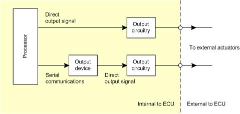
For an output, the application calls the necessary function and the data to be written is buffered and actioned some time later. Once the model has completed each model rate once, the buffered data is actioned at the quickest rate which writes the indirect output.
Indirect I/O always occurs when there is an device between the processor and the pin. The device communicates to the processor across a serial link and it is this communication which introduces the delay. Only I/O channels noted as serial in the technical specification (see Section 1.1, “ECU hardware reference documentation”) are affected.
Each target ECU provides some measure of feedback for a subset of the output pins. For instance, measuring the reference voltage for A/D conversions to determine if the reference voltage generator has failed. A complete list of the monitors can be found in the technical specifications (see Section 1.1, “ECU hardware reference documentation”). Each monitor is read by using one of the blocks, e.g., using the Section 5.1.5, “Analogue input — basic (pai_BasicAnalogInput)” block to read the analogue voltage of a monitor.