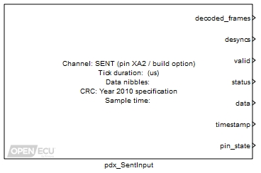
The SENT input block (Single Edge Nibble Transmission) decodes a SENT sensor's transmission pulses according to SAE J2716 Jan 2010, making available the sensor's status and data information.
None (Main library). (See Section 2.3, “Licensed Features”.)
The SENT input block decodes a sensor's transmission pulses according to SAE J2716 Jan 2010, making available the sensor's status and data information. SAE J2716 describes SENT as:
The Single Edge Nibble Transmission encoding scheme (SENT) is intended for use in applications where high resolution sensor data needs to be communicated from a sensor to an Engine Control Unit (ECU). It is intended as a replacement for the lower resolution methods of 10 bit A/D converters and PWM and as a simpler low cost alternative to CAN or LIN. The implementation assumes that the sensor is a smart sensor containing a microprocessor or dedicated logic device (ASIC) to create the signal.
SENT is a unidirectional communications scheme from sensor (transmitting) device to controller (receiving) device which does not include a coordination signal from the controller/receiving device. The sensor signal is transmitted as a series of pulses with data encoded as falling to falling edge periods.
The SENT input block:
- decodes the SENT transmission into status and fast data nibbles;
- stores the last received, decoded and verified status and data nibbles;
- allows for a transmitter clock tick variance of ± 25% for the calibration and synchronisation pulse;
- allows for a transmitter clock tick between [3, 90] microseconds;
- allows for an optional pause pulse between transmissions;
- uses the calibration and sychronisation pulse to ratiometrically adjust the status, data and CRC pulses;
- verifies the frame size (checks the expected number of nibbles, or frame edges);
- verifies the frame CRC, either the 2008 or 2010 version;
- verifies that successive calibration pulses differ by no more than ± 1.5625%.
For short or enhanced serial message reception over 16 or 18 consecutive SENT frames, see the pdx_SentSerialInput block.
Available when Provide simulation input? is ticked. The value of this inport is copied to the corresponding outport during model simulation.
Value type: Integer Available when Provide simulation input? is ticked. The value of this inport is copied to the corresponding outport during model simulation.
Value type: Integer Available when Provide simulation input? is ticked. The value of this inport is copied to the corresponding outport during model simulation.
Value type: Integer Available when Provide simulation input? is ticked. The value of this inport is copied to the corresponding outport during model simulation.
Value type: Integer Available when Provide simulation input? is ticked. The value of this inport is copied to the corresponding outport during model simulation.
Value type: Integer Available when Provide simulation input? is ticked. The value of this inport is copied to the corresponding outport during model simulation.
Value type: Integer Available when Provide simulation input? is ticked. The value of this inport is copied to the corresponding outport during model simulation.
Value type: Integer
A counter incremented for each frame that is successfully received, decoded and verified.
Range: [0, inf] frames, modulo 256
Value type: Integer A counter incremented for each loss of synchronisation with the SENT sensor pulse stream. Loss of synchronisation occurs when the block pulse decoder has not seen a valid pulse for more than 125% of a calibration pulse duration (where a calibration pulse is 56 SENT ticks, Tick length); or a calibration, status, nibble or CRC pulse is too short; or the frame CRC verification fails.
Range: [0, inf] frames, modulo 256
Value type: Integer 1 if at least one SENT frame has been successfully received, decoded and verified, 0 otherwise. If 1, then the status and data outports provide the status and data received from the last frame, and the timestamp outport provides the time when the frame was received.
Range: 0 or 1
Value type: Boolean The status nibble of the last SENT frame that was successfully received, decoded and verified. Set to zero when a SENT frame has not been successfully received.
Range: 0 or 1
Value type: Integer The data nibbles of the last SENT frame that was successfully received, decoded and verified. Set to zero when a SENT frame has not been successfully received. The data nibbles are packed into the integer right aligned.
Range: [0, 16777215] unitless
Value type: Integer A timestamp taken when the last SENT frame was fully received, decoded and verified. The timestamp increments in counts of 256, wrapping approximately every 4 seconds. The timestamp can be used by the application to determine whether the SENT sensor is transmitting data at the expected period.
Range: [0, inf] counts, modulo 4294967296
Value type: Integer 1 if the channel pin voltage is above the detection threshold, 0 otherwise. Can be used by the application for electrical diagnostics.
Range: 0 or 1
Value type: Boolean
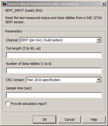
The channel pin for this SENT input.
Value type: List Calibratable: No The length of the SENT sensor's transmission clock tick connected to this channel.
Range: [3, 90] microseconds Resolution: 0.1 microseconds
Value type: Real Calibratable: Yes, offline The number of data nibbles transmitted by the SENT sensor in each frame.
Range: [1, 6] nibbles
Value type: Integer Calibratable: Yes, offline The version of CRC algorithm used by the SENT sensor.
Value type: List Calibratable: Yes, offline The periodicity of the block execution.
Range: [0.001, 3600] seconds
Value type: Real Calibratable: No If selected then the block creates simulation inports for each of the outports.
Value type: Boolean Calibratable: No