Measure a PWM signal and derive the frequency and duty cycle.
None (Main library). (See Section 2.3, “Licensed Features”.)
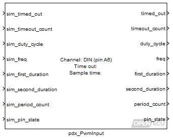
The input block measures a PWM signal and performs a number of operations:
- Frequency measurement
The block measures the time of each high and low (or low and high) pulse to determine the frequency of the input signal.

Whether the block measures a low pulse followed by a high pulse, or a high pulse followed by a low pulse is determined by the Invert block parameter.
- Pulse measurement
The block measures the durations of the first and second pulses and derives the duty cycle (first pulse time divided by the cycle time). Very small duty cycles (less than 1% or greater than 99%) will not be measured accurately or at all.
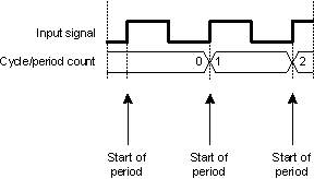
- Period count
The block accumulates the count of complete periods modulo 16777216. The application calculated difference of counts between iterations of the block could be used to diagnose unexpected changes in the signal.
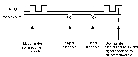
- Timeout check
The block measures the period duration and determines whether the signal has taken longer than the Time out duration. The block accumulates the count of time out events, and provides an outport to indicate if the signal is timed out when the block iterates.
Only used in simulation. Place 1 here to simulate a time out, zero otherwise.
Range: 0 or 1
Value type: Boolean Only used in simulation. Place a count here to simulate the count of time outs in the input signal.
Range: [0, 16777215]
Value type: Integer Only used in simulation. Place a duty cycle here to simulate the duty cycle of the last measured period.
Range: [0, 1] duty-cycle
Value type: Real Only used in simulation. Place a frequency in Hz here to simulate the frequency of the last measured period.
Value type: Real Only used in simulation. Place a duration in microseconds here to simulate the first pulse from the last measured period.
Range: [0, 2000000] microseconds
Value type: Integer Only used in simulation. Place a duration in microseconds here to simulate the second pulse from the last measured period.
Range: [0, 2000000] microseconds
Value type: Integer Only used in simulation. Place a count here to simulate the count of periods seen in the input signal.
Range: [0, 16777215]
Value type: Integer Only used in simulation. Place a zero or 1 here to simulate the pin state sample.
Range: 0 or 1
Value type: Boolean
1 if a complete period has not been measured for the timeout given by the mask parameter Time out, zero otherwise.
Range: 0 or 1
Value type: Boolean A count of the time outs, wrapped modulo 16777216.
Range: [0, 16777215]
Value type: Integer Ratio of the first pulse duration to the period, or zero if no measurement has been taken.
Range: [0, 1] duty-cycle
Value type: Real Calibratable: No Frequency of the last measured period, or zero if no measurement has been taken. The range of the frequency is limited in various ways.
The range of the frequency that can be measured is limited by the filter circuitry of the input pin.
The lowest measurable frequency is limited by the filter circuitry and the size of the corresponding processor timer for a channel. Any input frequency below the documented limit, is reported as timed-out.
The highest measurable frequency is limited by the filter circuitry and the resolution of the corresponding processor timer for a channel. In general, the block reports the frequency of the filtered signal and the input filtering forms an upper limit. However, as the frequency increases, the resolution of measurement decreases.
Details of the input pin's filtering and processor timing can be found in an ECU's technical specification.
Range: [0.5, ...] Hz
Value type: Real The duration of the first pulse from the last measured period, or zero if no measurement has been taken.
Range: [0, 2000000] microseconds
Value type: Integer The duration of the second pulse from the last measured period, or zero if no measurement has been taken.
Range: [0, 2000000] microseconds
Value type: Integer A count of the periods, wrapped modulo 16777216.
Range: [0, 16777215]
Value type: Integer Calibratable: No Set to 1 if the input signal is high when the block iterates, set to zero if the input signal is low when the block iterates.
Range: 0 or 1
Value type: Boolean Calibratable: No
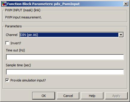
The input pin sourcing the signal to measure.
Value type: List Calibratable: No Whether the first pulse in the period will be high (option unticked) or low (option ticked). This option does not consider any inversion performed by the hardware, the user must do so.
Value type: Boolean Calibratable: No The period of time after which if no complete period has been measured, the outport timed_out is set to 1.
Range: [0.5, 10000] Hz
Value type: Real Calibratable: Yes, offline and online The periodicity of the block execution.
Range: [0.001, 3600] seconds
Value type: Real Calibratable: No If selected then create simulation inports for each of the outport message signals.
Value type: Boolean Calibratable: No