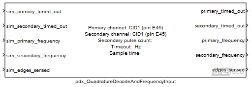
Output the number of edges sensed from the quadrature encoder since the last time the block iterated. Output the last measured frequency of the primary and secondary channels.
None (Main library). (See Section 2.3, “Licensed Features”.)
This block decodes the signals from a quadrature encoder. A quadrature encoder generates a pulse train from two sensors which pick up markings on the encoder disk.
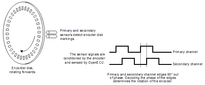
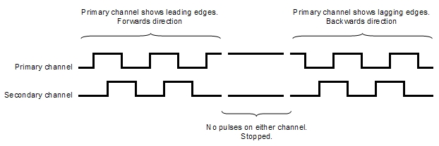
The sensors and markings are arranged so that when the encoder is turning, the sensor signals generate two pulse trains 90° out of phase. If the disk is turning in a forwards direction, the primary channel edges will lead the secondary channel edges. If the disk is turning in a backwards direction then the primary channel edges will lag the secondary channel edges. If there are no signal edges on either channel after a period of time, then the encoder has stopped turning (or is turning slowly enough to be considered stationary).
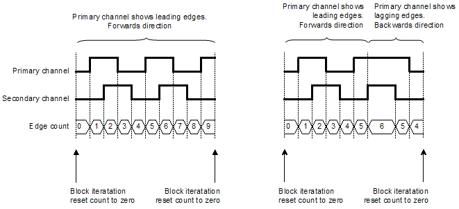
The quadrature decode block measures the primary and secondary channels, determines the direction at each pulse and counts the pulses. If the encoder is turning forwards then for each edge on the primary and secondary channels, the block increments the count. If the encoder is turning backwards then for each edge on the primary and secondary channels, the block decrements the count. When the block iterates, it outputs the count of pulses and resets the count to zero.
For instance, if the encoder turns forwards for nine edges between iterations of the block, the block output will be nine. If the encoder turns forwards for six edges and then backwards for two edges between executions of the block, the block output will be four.
Note
Some encoders provide an index signal and some encoders provide complement signals of the primary and secondary signals, both for the purposes of improving reliability. This block does not decode these signals.
The block also measures the duration of each pulse from the encoder primary and secondary channels and outputs the last measured frequency of each channel. If the frequency of a channel has not been measured (because a complete signal pulse has not yet occurred), then the corresponding frequency outport is set to zero.
If the primary or secondary channel does not complete a pulse for longer than the block's timeout value, then the corresponding primary_timed_out and secondary_timed_out outports of the block are set. When a timeout occurs, the frequency outport for that channel remains at its last known frequency measurement (or zero if a measurement has not been completed).
Only used in simulation. Place 1 here to simulate a time out for the primary channel frequency measurement, 0 otherwise.
Range: 0 or 1
Only used in simulation. Place 1 here to simulate a time out for the secondary channel frequency measurement, 0 otherwise.
Range: 0 or 1
Only used in simulation. Place the frequency in hertz here to simulate the last measured primary channel frequency. A measurement of zero hertz indicates that no measurement is available.
Only used in simulation. Place the frequency in hertz here to simulate the last measured secondary channel frequency. A measurement of zero hertz indicates that no measurement is available.
Only used in simulation. Place the count of edges here to simulate the number of edges sensed since the last execution of this block. A value of zero indicates that the encoder position is at the same place as it was when the block was last iterated.
Range: [-8388608, 8388607] edges (for M221, M250, M460, M461, and M670 targets)
1 if the primary channel input signal has not completed a pulse within the mask parameter timeout period at the point of sampling (see the mask parameter section below), 0 otherwise.
Range: 0 or 1
1 if the secondary channel input signal has not completed a pulse within the mask parameter timeout period at the point of sampling (see the mask parameter section below), 0 otherwise.
Range: 0 or 1
The last measured primary channel frequency in hertz, or 0 if no measurement has been taken (regardless of the state of outport primary_timed_out). The range of the frequency is limited in various ways.
The range of the frequency that can be measured is limited by the filter circuitry of the input pin.
The lowest measurable frequency is limited by the filter circuitry and the size of the corresponding processor timer for a channel. Any input frequency below the documented limit, is reported as timed-out.
The highest measurable frequency is limited by the filter circuitry and the resolution of the corresponding processor timer for a channel. In general, the block reports the frequency of the filtered signal and the input filtering forms an upper limit. However, as the frequency increases, the resolution of measurement decreases.
Details of the input pin's filtering and processor timing can be found in an ECU's technical specification.
Range: [0.5, ...] Hz (for M221, M250, M460, M461 and M670 targets)
The last measured secondary channel frequency in hertz, or 0 if no measurement has been taken (regardless of the state of outport secondary_timed_out).
Range: [0.5, ...] Hz (for M221, M250, M460, M461 and M670 targets)
The count of edges sensed since the last time the block was iterated. A value of zero indicates that the the encoder position is at the same place as it was when the block was last iterated.
Range: [-8388608, 8388607] edges (for M221, M250, M460, M461 and M670 targets)
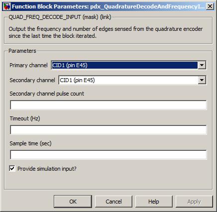
The input pin sourcing the primary signal to measure. The relationship between the primary and secondary channels is explained above.
The input pin sourcing the secondary signal to measure. The relationship between the primary and secondary channels is explained above.
The number of pulses to accumulate when calculating the frequency for the secondary input channel. The primary channel frequency is always calculated by measuring one complete pulse.
Range: [1, 255] pulses
The period of time in hertz after which if no complete pulse has been measured for the primary or secondary channel, the corresponding outports primary_timed_out and secondary_timed_out are set to 1.
Range: [0.5, 10000] Hz (for M221, M250, M460, M461 and M670 targets)
The periodicity of the block iteration.
Range: [0.001, 3600] seconds
If the edges_sensed outport is zero, it means the encoder position is in the same position as it was when the block was last iterated. This can occur if the encoder position has not moved, or if the encoder position has moved and returned to its original position. This should be kept in mind if the block will be used to derive the encoder's velocity.
The block iteration period must be sufficient to ensure that the sum of leading and lagging edges is no more than 8388607 (for M221, M250, M460, M461 and M670 targets) between iterations of the block. If the sum of edges is greater then the edges_sensed outport will wrap with modulo arithmetic, (24-bit for M221, M250, M460, M461 and M670 targets).
The primary and secondary frequency outports may differ in value due to hardware filtering. A specific example of this would be where the two channels have differing low pass filters such that the input signals are cut off at different frequencies.