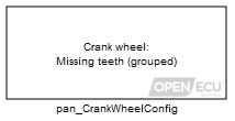
Configure a crankshaft wheel encoder input channel.
None (Main library). (See Section 2.3, “Licensed Features”.)

The application must use a pan_CrankWheelConfig block for each input channel to be attached to a crankshaft encoder wheel. A pan_CrankWheelConfig block must be present in the model for other crankshaft related blocks to operate. The block identifies the teeth arrangement for one crankshaft sensor input, including the number of teeth, sync points and their type.
The block supports crank trigger wheels with missing teeth or an extra tooth. Common crank trigger wheels, such as 12+1 and 36-1 are supported:

As are less common wheel patterns, such as 24-1-1-1 or 36-1-2-3:

Where supported, the application can use the pan_CrankWheelConfigExt block to further define how the crankshaft signal is processed for electrical noise, sync point detection and more.
See Section 6.1.1, “Crankshaft position sensor processing” for a general description of how the ECU processes different crank sensor signals, and see the ECU's Technical Specification for details specific to an ECU. In particular, note that some ECUs (such as the M670) invert the crankshaft sensor signal in circuitry, which must be taken in to account with the Tooth edge polarity mask parameter. Please see the crank sensor input section of the ECU's Technical Specification to determine polarity settings. The ECU does not diagnose an inverted crank signal.
The block makes a distinction between primary and secondary crankshaft encoding wheels. A primary wheel can drive the angle clock, as described in Section 6.1.4, “Angle clock”. A secondary wheel cannot drive the angle clock but can be used to determine phasing between the primary wheel and itself.

A drop down to identify the crankshaft wheel to configure. The selection of wheel is dependent on the target ECU hardware selected in the put_Identification block.
Value type: List Calibratable: No Specifies the input channel for the crankshaft sensor input selected for this Wheel. The selection of channel is dependent on the target ECU selected in the put_Identification block.
Value type: List Calibratable: No Specifies the expected pattern of teeth on the crankshaft encoding Wheel. The selection of wheel type is dependent on the target ECU selected in the put_Identification block.
- Missing teeth (grouped)
A crankshaft wheel encoder with a series of equally spaced teeth followed by a gap equal in width to 1 or more teeth (the gap is often referred to as “missing teeth”).

- Extra teeth (grouped)
A crankshaft wheel encoder with a series of equally spaced teeth with an extra tooth placed equally between two others.

Value type: List Calibratable: No Specifies the algorithm to use when detecting crank synchronisation points (see Section 6.1.2.2, “Crank wheel sync points”. The selection of algorithm is dependent on the target ECU selected in the put_Identification block.
Value type: List Calibratable: No Specifies the number of teeth on the crankshaft encoding wheel, plus any missing teeth but ignoring an extra teeth. For example, use 60 for a 60-2 wheel, 36 for a 36-1-1 wheel, 12 for a 12+1 wheel, and 12 for a 12+1+1 wheel.
Range: [12, 60] teeth
Value type: Integer Calibratable: No Specifies the number of teeth involved in one of the sync points of the crankshaft wheel encoder. Negative integers indicate missing teeth, positive integers represent extra teeth.
Range: [-1, -3] or 1, crank teeth
Value type: Integer Calibratable: No Specifies the polarity of the input signal to be used as the tooth indication when decoding the crankshaft wheel. Note that this polarity refers to the processed signal to the microprocessor, and therefore its meaning with respect to the polarity on the external pin varies between target ECUs, as detailed below.
- Default
With this choice, for a Hall-effect signal, a falling edge is the tooth indication. For a VR signal, the tooth indication always corresponds to the zero crossing point where the positive signal falls below the negative signal. Note that for a VR signal, the default selection should always be preferred, since the other edge of the processed signal will correspond to the arming point (when the voltage rises above a threshold that depends on the previous peak values) and is less accurate as a reference point. Since a variable reluctance sensor typically has two output signals, one can always ensure that the positive-to-negative zero crossing point matches the desired tooth indication by swapping the connections if necessary.
- Falling
The interpretation of this field depends on the target ECU hardware selected in the put_Identification block. For the M221 and M250 targets, “Falling” is the same as “Default”.
- Rising
The interpretation of this field depends on the target ECU hardware selected in the put_Identification block. For the M220 and M670 targets, “Rising” is the same as “Default”.
Value type: List Calibratable: No