As outlined in Section 4.2.5, “Build model”, a model build creates the target ECU images which can be programmed onto an ECU and run in real-time. Figure 4.8, “Building an application (in outline)” gives an outline of the build process.
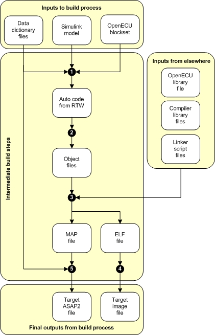
The build process has a number of inputs:
- Data dictionary files
The data dictionary files describe the data variables of the application code. Data variables are all C global variables, either RAM or ROM based. For each data variable which must be accessible from the calibration tool, there is a corresponding data dictionary element (DDE) which details attributes of the data variable, like description, type, units, and so on. See Section 4.2.2.2, “Data dictionary files”. for more.
The user must provide the data dictionaries.
- Simulink model
The application in model form. There are some restrictions on what the model can contain, see Section 4.3.1, “Block use restrictions”.
The user must provide the model.
- Simulink blockset
Supporting Simulink blocks which provide direct access to the ECU's functionality. OpenECU software provides the Simulink blockset. An overview of the blockset is given in Section 4.6, “OpenECU blockset features”.
- OpenECU library file
A compiler specific library file for OpenECU. The library file is linked with the application object files to create a binary image for execution on the target.
OpenECU software provides the library file.
- Compiler library file
The compiler's own support libraries (e.g., implementation of the C standard library or compiler specific extensions).
The compiler software provides the library file.
- Linker script files
The scripts tell the compiler how to combine the application object files, interface object files and libraries to create the binary image to run on the target ECU. This includes details about the layout of memory and how object file sections are allocated to memory.
OpenECU software provides the linker files.
The inputs are processed in a number of steps to create intermediate objects:
Runs RTW to generate C code from the Simulink model and DDEs. The generated C code includes the implementation of the model logic and any necessary code to bind the model with the OpenECU and compiler libraries.
Runs the compiler for the application code files. The compiler generates object files used in the link stage.
Runs the linker to combine the object files from the application and interface tool, as well as the compiler's library and OpenECU libraries, to generate an ELF file.
Runs support tools and scripts to extract a binary image of the application from the ELF file. At this stage, the binary image is modified with check-sums and auxiliary data to support robust operation on the ECU.
Runs support tools and scripts to generate an ASAP2 file from the target and DDE information. The ASAP2 file is used during reprogramming and calibration of the ECU.
From those intermediate steps, the final set of objects are created:
- Target ASAP2 file
An ASAP2 file details the memory areas used by the binary application image as well as how DDEs have been allocated to memory. The ASAP2 file is used by PC based tools to reprogram an ECU or to calibrate an ECU. See Section 4.5, “Programming an ECU” and Appendix 2, Supporting tools for more.
- Target image file
The target image file contains the binary image of the application code and data. Once an ECU is programmed with the image file, the application can be executed. See Section 4.5, “Programming an ECU” for more.
To build the executable code for the ECU, select the model window so
it becomes focused then press CTRL+B to start the RTW build.
Alternatively, place a prtw_Build block in
the model and double click the block.
The build process starts by re-reading the build list to ensure the latest DDE information is present when generating the ASAP2 file.
### Starting Real-Time Workshop build procedure (with modification for OpenECU) for model:
Clearing any previously loaded build list...
Obtaining workspace data from each feature data dictionary...
Workspace variables loaded
The build then continues with the standard RTW build mechanism with a few additions for OpenECU. In some earlier versions of RTW, if this is the first time the model has been built, the build creates the RTW library which can take some minutes to complete. Subsequent builds of the same model skip this part of the build.
During the build, MATLAB will display a series of diagnostic and status messages with respect to the build. In MATLAB versions prior to r2014b, all messages will be logged to the main MATLAB console.
In MATLAB versions r2014b and later messages will be logged to The Diagnostic viewer window. This window can be viewed by clicking the link at the bottom of the model window.

If the build is successful, a number of files will be created:
model_name_tool_generic.a2l — the generic ASAP2 file for the build model;
model_name_tool_inca.a2l — the ETAS INCA specific ASAP2 file for the build model;
model_name_tool_vision.a2l — the ATI Vision specific ASAP2 file for the build model;
model_name_tool_canape.a2l — the Vector CANape specific ASAP2 file for the build model;
model_name_tool_vision.vst — the ATI Vision Strategy file for the build model (combined ASAP2 and S-record file — only generated if a compatible version of ATI Vision is installed, see the image generation options in Section 4.3.4, “Configuration options”);
model_name.a2l.err — any errors that resulted from creating the ASAP2 file (if there are any errors, a short extract is displayed at the end of the build);
model_name_image_small.s37 — the image bytes to program into the OpenECU in Motorola S-record format (small representing the minimum amount of code and data bytes to program the OpenECU device) — suitable for the ATI Vision calibration tool;
model_name_image_small.hex — the image bytes to program into the OpenECU in Intel HEX format — suitable for the Vector CANape calibration tool;
model_name.elf — the compiler's version of some of the above files — suitable for the PiSnoop development tool;
model_name.snx — lists of variables PiSnoop will show or hide automatically — suitable for the PiSnoop development tool;
where the text model_name denotes the name of your .mdl model file. Each of these files can be found in the same directory as your model file.
Note
A subset of these files can be produced by altering the OpenECU RTW options
(accessed by opening an OpenECU model and selecting the menu option
Simulation -> Simulation parameters... then browsing
to the OpenECU options under Real-Time Workshop.
More details on these settings are given in Section 4.3.4, “Configuration options”.
One of the ASAP2 files and one of the image files can now be used with a calibration tool to program the ECU via CCP (or if you are using a recent version of ATI Vision, you can simply use the strategy file).
Also at the end of a successful build, a short summary of the memory used by the model is displayed. It looks a little like:
Strategy memory:
 142696 bytes of strategy/code memory used
 250519 bytes remaining
Calibration memory:
   3376 bytes of calibration memory used (rough indication, includes Simulink support data)
 258767 bytes remaining
Workspace memory:
  14040 bytes of workspace/displayable memory used, including
    176 bytes of adaptive data, and
      2 bytes of diagnostic trouble code data, and
   8192 bytes of model stack
  24008 bytes remaining
Built at: 2005, 08, 02 (year, month, day) 10:52:47 (hour:min:sec)
but the values will vary based on your model.
- Strategy memory
Shows the amount of model code used and remaining.
- Calibration memory
Shows the amount of calibration data (as well as Simulink support data) used and remaining.
- Workspace memory
Shows the amount of used and remaining RAM, where RAM is used for general model calculations and signals, adaptive data and overall program stack.
As your model develops, it is useful to take regular snap shots of the
memory usage to determine how quickly development is using up memory
(and the same can be done by taking regular snap shots of the ASAP2
variables mpl_cpu_loaded and mpl_max_used_stack
to determine how quickly development is using up CPU resources).
There are a couple of sources of long build times.
- Building the RTW library source code
It can take some time to build the RTW sources, increasing in duration with increasing versions of MATLAB.
The commands to compile the RTW sources are easily recognisable during a build, where each source file that belongs to the RTW library starts with
rt_.dcc -@mk_rtw_cc_opts.cfg -o rt_atan2.o [path]\rt_atan2.c ...Versions of MATLAB after R2008a (inclusive) do not require the RTW library source code to be built in full and do not suffer from the larger compile times when building a model for the first time.
- Building the model source code
With versions of Diab 5.5.1.0 and later, larger models can take a significant amount of time to compile. This is due to a buffer size issue with the compiler. See Section 1.5.9.3, “Known issues” for a description of the work around to be used with the pcomp_CompileOptions block.
There are a couple of warnings and errors that occur more often than others and its worth reviewing those here:
- Cannot find the Diab compiler
An error message, similar to the following, indicates that the Diab compiler could not be found.
dcc -@mk_rtw_cc_opts.cfg -o [file-name].o [path to file].c
'dcc' is not recognized as an internal or external command,
operable program or batch file.
In order for the Diab compiler to run, the compiler must be installed and the the path to the compiler must be specified in one of two environment variables. See the instructions provided in the installation guide, Section 1.5, “Integration notes for third party tools”.
- Cannot run the Diab compiler
An error message, similar to any of the following, indicates that the Diab compiler cannot find a license.
fatal error (dcc:1635): License error: FLEXlm error:
      Cannot find license file (-1,73:2 "No such file or directory")
fatal error (dcc:1635): License error: FLEXlm error:
      No such feature exists (-5,357)
In order for the Diab compiler to run, it must have access to a valid license. The Diab compiler license is created by WindRiver after you purchase the compiler. If you run into trouble with your Diab compiler license, please contact OpenECU technical support and we will try to help out.
- Model too large for ECU memory space
An error message, similar to any of the following, indicates that the model has become too large for the target ECU.
dld -@mk_model_link_opts.cfg -@O=[model-name].map -o [model-name].elf
dld: '.' (0x[string]) is assigned invalid value: 0x[string]
The ECU has various memory spaces of finite size. If the model becomes too large to fit into these memory spaces, then the Diab linker will raise an error. It may be possible to optimise the build to reduce the final model size. Please contact OpenECU technical support and we will try to help out.
- Model uses absolute time
A warning message, similar to the following, indicates that the model uses absolute time.
### RTW build information:
Warning: the RTW generated code was found to contain calls to
         functions that access absolute time. See the OpenECU,
         Simulink and RTW documentation about absolute time,
         including a list of blocks that depend on absolute time.
         After a period of time, Simulink's absolute time will
         eventually saturate and blocks that use absolute time
         will fail to work correctly (including some functionality
         of blocks in triggered subsystems).
As part of the build process, OpenECU checks the Simulink/RTW generated code to determine if the model uses absolute time. Absolute time has some limitations, see Section 5.1.112, “Time (Simulink) (ptm_SimulinkTime)” for more.