Discrete IO Troubleshooting
Troubleshooting discrete I/O
Discrete I/O refers to signals that have a dedicated connector pin for a given input or output function. This is in contrast to network or communication I/O such as CAN.
Digital outputs
My simple digital output doesn’t seem to be doing anything - what’s wrong?
1. We recommend using a boolean calibration to drive the digital output during troubleshooting. This allows you to easily control the output.
Confirm you have a correct external load on the digital output.
Most low-side outputs require a load pulled to battery or pulled to one of the ECU’s high-side supplies.
Without the external load, you’re unlikely to see the voltage of the digital output pin change since most outputs will be near ground voltage when not driven.
See the Technical Specification for details regarding the digital outputs.
Double-check the application to confirm you are controlling the correct boolean calibration.
Try moving to a different output pin.
This will determine if the ECU has a problem with a particular pin.
My PWM/frequency output doesn’t seem to be doing anything - what’s wrong?
We recommend using a real_T calibration to drive your PWM output during troubleshooting. This allows you to easily control the output.
Confirm you have a correct external load on your PWM output.
Most low-side outputs require a load pulled to battery or pulled to one of the ECU’s high-side supplies.
Without the external load, you’re unlikely to see the voltage of the output pin change since most outputs will be near ground voltage when not driven.
See the Technical Specification for details regarding digital outputs.
Double-check the application to confirm you are controlling the correct calibration.
Note that the PWM output takes a value from 0.0 - 1.0. Any input greater than 1.0 will result in outputting 100% duty cycle.
Try moving to a different output pin.
This will determine if the ECU has a problem with a particular pin.
My output seems inverted compared to what I thought it should be (or compared to other outputs)
Some outputs are inverted. See the “Digital outputs” section of the Technical Specification for details regarding digital outputs.
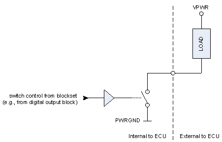
Low Side vs. High Side Digital Outputs
Most digital outputs like PWM and Frequency signals are Low Side Drive, as shown in the diagram below. In order to measure a change on the output pin, you must connect a load resistance between the output pin and a supply voltage.
Some OpenECU modules have 1 or more high side outputs, which have a High Side Drive circuit as shown in the diagram below. In order to measure a change on the output pin, you must connect a load resistance between the output pin and ground.

My M670 is indicating a fault on Monitor (Fault) - what’s wrong?
This signal, Monitor (Fault), is an active low fault reported by the pre-driver controlling the outputs. When it is low, it indicates at least one fault has been detected on one or more of the listed digital outputs:
Monitor (off ol)
Monitor (on ol)
Monitor (ov)
Monitor (sb)
Monitor (sb tested)
Monitor (sg)
Monitor (sg+ol tested)
See the Internal signals section of the Technical Specification for details.
Digital inputs
My digital input doesn’t seem to be doing anything - what’s wrong?
Check the voltage on the pin of the digital input when the input is driven high and low.
Open the Technical Specification for the ECU and find the Digital inputs section.
Compare the high and low voltages to confirm that the input is correctly crossing the switching thresholds.
Double-check the application and data dictionaries to confirm you are watching the correct signal.
Verify that the signal label and data type are correct in Simulink and the data dictionary.
Make sure the signal properties in Simulink are set to Exported Global in the Real-Time Workshop tab.
Try moving to a different input pin to identify if the ECU has an issue with a specific pin.
My input seems inverted
Some inputs are inverted. See the Digital inputs section of the Technical Specification for details.
Analog inputs
Follow the steps below for troubleshooting:
Measure the voltage at the analog input pin.
Double-check the application and data dictionaries to confirm you are watching the correct signal.
Verify that the signal label and data type are correct in Simulink and the data dictionary.
Make sure the signal properties in Simulink are set to Exported Global in the Real-Time Workshop tab.
Try moving to a different output pin to determine if there’s an issue with a specific pin.