Define a diagnostic trouble code, and provide the platform with information relating to its fault conditions.
EXT_DIAG (Extended diagnostics library). (See Section 2.3, “Licensed Features”.)
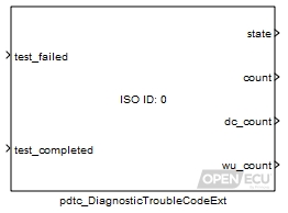
A diagnostic trouble code (DTC) is a unique indicator used to remember the state of a fault. This block supports platform-controlled fault handling for emissions-related and non-emissions-related faults. The model determines if the conditions for progressing the platform's fault handling state machine are satisfied or not, and passes this information to the pdtc_DiagnosticTroubleCodeExt block. The state of any fault can be maintained by the block while the model is running, and also across power cycles (see the pdtc_Memory block for more details).
There are two types of DTC currently supported - J1939 and ISO-15765 - although more may be added in the future. Each DTC can be defined as either a single type, or a combination of both J1939 and ISO types.
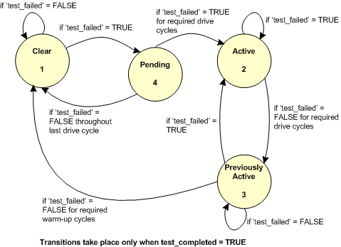
Each DTC can be in one of four states. Its state is Clear if its fault conditions have never been present, or if a previously active fault has healed itself (its fault conditions have not been present for a sufficient amount of time). Its state is Pending if its fault conditions are present, but have not been present for long enough to confirm the fault. Its state becomes Active if a Pending DTC's fault conditions persist long enough for it to be confirmed, or if a Previously Active DTC's fault conditions return. Its state becomes Previously Active if an Active DTC's fault conditions have been not been present for a sufficient amount of time.
The library will transition through the different states, Clear, Pending, Active and Previously Active based upon the inputs from the application, test_failed and test_completed as well as information regarding current drive cycle and warm up cycle count.
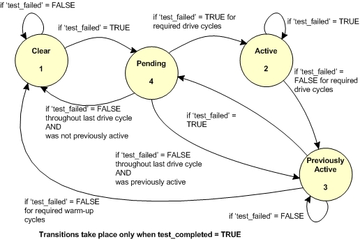
State transitions are also affected by the action selected when a DTC reaches Previously Active but the test then fails again. Behaviour in this situation is not specified by CARB (and therefore not by other OBD specifications deriving from CARB), so behaviour is manufacturer-specific. One possible interpretation is that the DTC should simply return immediately to Active. The other possible interpretation is that the DTC should return to Pending: in this case, if the test continues to fail then the DTC transitions to Active; or if the test passes for the duration of another drive cycle then the DTC returns back to Previously Active (instead of returning to Clear as a DTC would usually do from Pending state). Selection of the desired behaviour is configurable at the C-API level, but this has not yet been implemented in Simulink; Simulink models will currently always select the latter interpretation (transition to Pending) for DTC.
If transitions between Previously Active and Pending states are disabled, the following diagram describes the DTC state transitions.
If transitions between Previously Active and Pending states are enabled, the following diagram describes the DTC state transitions.
The library keeps track of drive cycles and warm-up cycles based on calls by the application to the pdtc_Control block.
Detection of warm-up and DTC ageing in the Previously Active state is not as straightforward as it might at first appear. OBD regulations (in particular CARB and European regulations) define "drive cycles" unambiguously, but are less clear on the definition of a "warm-up cycle". It has therefore been necessary to adopt an interpretation which is believed to be the most stringent possible interpretation, so that regulatory compliance can be assured. Regulations
The OpenECU interpretation of a warm-up cycle is "an ignition cycle in which a warm-up (as reported by the customer) occurs". The test causing a DTC to be raised must also run and pass during the same ignition cycle in which the warm-up occurs, in order for the DTC to be aged by one warm-up count. The following diagram describes scenarios which illustrate how this will work in an application.
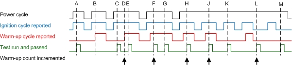
At points A and B a test has not been run and passed in the same warm-up cycle, so the warm-up count is not incremented.
At point C the warm-up has not yet occurred when the test is run and passed, so the warm-up count is not incremented. At point D the warm-up occurs, and as a result of the test having been previously run and passed, the warm-up count is incremented. Further instances of the test running and passing during this ignition cycle (E) do not affect the warm-up count, because this is required to count warm-ups and not test executions.
At point F the test is run and passed when the warm-up has already occurred, so the warm-up count is incremented immediately. Further instances of the test running and passing during this ignition cycle (G) again do not affect the warm-up count.
Due to power-hold relays, capacitors or other system behaviour, the ECU may not lose power when the ignition is cycled. Points H and J illustrate that tests carried out on subsequent ignition cycles with warm-ups will increment the warm-up count, even if the ECU has not been powered off. Point K illustrates that the requirement for test run and warm-up remains.
Tests may also be required to take place during the power-hold period. Point L illustrates that the warm-up count will be incremented during the power-hold period if a warm-up cycle has previously taken place this ignition cycle. Point M illustrates that the requirement for warm-up still exists during the power-hold period.
Note that this diagram does not mention drive cycles, as these are calculated independently and do not affect warm-up (except insofar as they are based on conditions arising in the same vehicle). Note also that the diagram does not mention warm-ups reported with the ignition off, because the regulatory definition of a warm-up requires the engine to be on (and hence the ignition to be on).
Changes to DTC states are written to non-volatile storage when block Section 5.1.40, “DTC memory update (pdtc_Memory)” is invoked with a request for commit to storage. This will typically occur on shutdown and at periodic intervals during execution. If DTCs have not changed since the last write to non-volatile storage, invocation of the block Section 5.1.40, “DTC memory update (pdtc_Memory)” has no effect, maximising the lifespan of non-volatile storage.
If the DTC cannot be recalled from non-volatile memory (which includes the first time the ECU is powered up), then the library initialises the DTC as follows:
Table 7.3. DTC initialisation values
| DTC information | Initial value |
|---|---|
| State | Clear |
| Number of Times Set Active Count | 0 |
| Drive Cycle Count | 0 |
| Warm-up Cycle Count | 0 |
| Test Run This Drive Cycle | No |
| Test Not Complete | Yes |
Set to the value of the current DTC state (see the DTC states descriptions for a list of states and values).
Value type: Integer Calibratable: No A count of the number of times a J1939 DTC has changed to the active state. Available only if the parameter DTC type is J1939 DTC, and currently not supported by the platform-controlled fault handling.
Range: [0, 127] counts - 0 to 126 (The value 127 is reserved for indicating not available).
Value type: Integer Calibratable: No Drive cycle count. The number of drive cycles to 'debounce' the DTC state before setting it to active. This is exported for information only, as the platform is responsible for progressing the state machine.
Range: [0, 127]
Value type: Integer Calibratable: No Warm-up cycle count. The number of warm-up cycles in which the DTC has not failed - used to 'heal' faults that are no longer present. This is exported for information only, as the platform is responsible for progressing the state machine.
Range: [0, 127]
Value type: Integer Calibratable: No
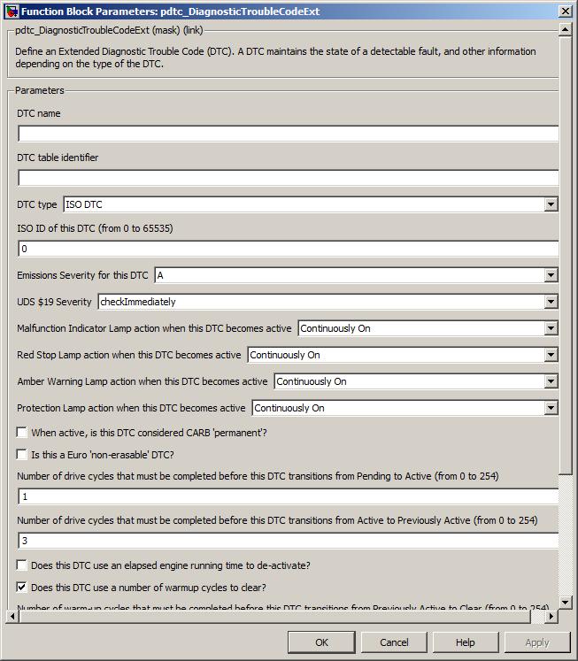
An optional name can be given to a DTC to identify it for calibrating the ID parameters. If no name is given, it will be allocated a name when the model is built. Note that this allocated name can change between builds, so should not be use for calibration. If a DTC will need to be calibrated, it should be explicitly named.
Generation of DDE entries for DTCs needs to be enabled. See Configuration options for more details.
Value type: String Calibratable: No The name of the DTC table to store this DTC in (there must be a corresponding named table specified in a pdtc_Table block in the model).
Value type: String Calibratable: No A drop-down selection of the type of the DTC.
Value type: List Calibratable: Yes, offline The value of the SPN for this DTC. The parameters Suspect parameter number, Failure mode indicator and Conversion method uniquely identify the DTC. Available only if the parameter DTC type includes J1939 DTC.
Range: [0, 524287]
Value type: Integer Calibratable: No The value of the FMI for this DTC. The parameters Suspect parameter number, Failure mode indicator and Conversion method uniquely identify the DTC. Available only if the parameter DTC type includes J1939 DTC.
Range: [0, 31]
Value type: Integer Calibratable: Yes, offline The value of the CM for this DTC. The parameters Suspect parameter number, Failure mode indicator and Conversion method uniquely identify the DTC. Available only if the parameter DTC type includes J1939 DTC.
Range: 0 or 1
Value type: Integer Calibratable: Yes, offline The value of the ID for this DTC. This ID uniquely identifies the DTC. Available only if the parameter DTC type includes ISO DTC.
Range: [0, 65535]
Value type: Integer Calibratable: Yes, offline A drop-down selection of the emissions severity level at which a DTC fits. This allows the modeller to combine "emissions related" and other DTCs within the same system.
Value type: List Calibratable: Yes, offline A drop-down selection of the UDS service $19 severity level for the DTC. Available only if the parameter DTC type includes ISO DTC.
Value type: List Calibratable: Yes, offline The action for the Malfunction Indicator Lamp when this DTC is active.
Range: [0, 3] (0 is Slow Flash, 1 is Fast Flash, 2 is On, 3 is Off)
Value type: Integer Calibratable: Yes, offline The action for the Red Stop Lamp when this DTC is active.
Range: [0, 3] (0 is Slow Flash, 1 is Fast Flash, 2 is On, 3 is Off)
Value type: Integer Calibratable: Yes, offline The action for the Amber Warning Lamp when this DTC is active.
Range: [0, 3] (0 is Slow Flash, 1 is Fast Flash, 2 is On, 3 is Off)
Value type: Integer Calibratable: Yes, offline The action for the Protection Lamp when this DTC is active.
Range: [0, 3] (0 is Slow Flash, 1 is Fast Flash, 2 is On, 3 is Off)
Value type: Integer Calibratable: Yes, offline Whether or not this DTC is considered 'permanent' (as defined by CARB/EPA) when the DTC is active. If the ECU is intended to comply with CARB, this should be selected for all DTCs that light the MIL.
Value type: Boolean Calibratable: Yes, offline Requires vehicle/operating conditions for OBD clear request
Available only if the parameter Permanent is true. CARB requires that for permanent DTCs, an OBD clear request does not immediately clear the DTC; instead the DTC may only be cleared when the ECU has verified that the fault is no longer present.
If this option is selected, vehicle/operating conditions as specified by CARB must have been met during a drive cycle since an OBD clear request was received, ensuring that the vehicle has been exercised over a range of behaviour which would be likely to detect any fault that still exists. The test for this DTC must then have been completed (during the same drive cycle or a later one) and report no fault existing. At the end of the drive cycle in which the test for this DTC is run, the DTC is cleared as per a normal OBD clear request.
If this option is unselected, vehicle/operating conditions are not required. The test for this DTC must have been completed and report no fault existing since the OBD clear request was received. At the end of the drive cycle in which the test for this DTC is run, the DTC is cleared as per a normal OBD clear request.
Vehicle/operating conditions met is indicated by the inport ok_to_clr_perm to the block pdtc_Control.
CARB requires that this option is selected for DTCs relating to specific monitors, and optionally may be selected for DTCs relating to other monitors.
Value type: Boolean Calibratable: Yes, offline Whether or not this DTC is non-erasable (as defined by Euro regulations).
Value type: Boolean Calibratable: Yes, offline The number of drive cycles for which the fault condition must be present before this DTC automatically transitions from Pending to Active. By default, this parameter is set to 1 (as recommended by the CARB regulations).
Range: [0, 255]
Value type: Integer Calibratable: Yes, offline Previously active drive cycles
The number of drive cycles for which the fault condition must be absent before this DTC automatically transitions from Active to Previously Active. By default, this parameter is set to 3 (as recommended by the CARB regulations).
Range: [0, 255]
Value type: Integer Calibratable: Yes, offline DTC de-activate using engine running time
Whether or not this DTC uses elapsed engine running time for it to transition from Active to Previously Active.
Value type: Boolean Calibratable: Yes, offline Elapsed engine running time for de-activation
The value of the elapsed engine running time for the DTC to transition from Active to Previously Active Available only if the parameter DTC de-activate using engine running time is checked.
Range: [0, 47185920] seconds
Value type: Integer Calibratable: Yes, offline Whether or not this DTC uses warmup cycles for it to transition from Previously Active to Clear.
Value type: Boolean Calibratable: Yes, offline The number of warm-up cycles for which the fault condition must be absent before this DTC automatically transitions from Previously Active to Clear. By default, this parameter is set to 40 (as recommended by the CARB regulations). Available only if the parameter DTC clear using warmup cycles is checked.
Range: [0, 255]
Value type: Integer Calibratable: Yes, offline DTC clear using engine running time
Whether or not this DTC uses elapsed engine running time for it to transition from Previously Active to Clear.
Value type: Boolean Calibratable: Yes, offline Elapsed engine running time for clear
The value of the elapsed engine running time for the DTC to transition from Previously Active to Clear. Available only if the parameter DTC clear using engine running time is checked.
Range: [0, 47185920] seconds
Value type: Integer Calibratable: Yes, offline Regulated exhaust level exceedance DTC
Whether or not regulated exhaust level exceedance applies to this DTC.
Value type: Boolean Calibratable: Yes, offline Whether or not this DTC has torque derate.
Value type: Boolean Calibratable: Yes, offline The amount of time until the derate will occur, should this DTC become active. Available only if the parameter Has torque derate is checked.
Range: [0, 225000] seconds
Value type: Integer Calibratable: Yes, offline Freeze frame associated with this DTC
A reference to the name of the frame frame to capture is entered here (see pff_FreezeFrame for specifics).
Value type: String Calibratable: No