Receive a CAN message and unpack the message contents.
None (Main library). (See Section 2.3, “Licensed Features”.)
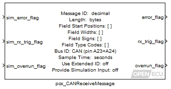
When a matching CAN message to this block is received, the block unpacks the message contents into individual signals, as specified by the block mask parameters, and provides them as outports. It is up to the application to provide an appropriate response (if one is required).
The block can provide a time stamp of when the message was received (see block mask parameter Provide Timestamp). The time stamp is a low accuracy time stamp, taken a short period of time after the message is received. That period of time is variable depending on the load of the processor and will therefore suffer jitter.
The pcx_CANdb_ReceiveMessage block provides a more convenient mechanism for specifying CAN information.
Warning
The PCX feature takes precedence over the PJ1939 feature. If you configure the PCX feature to receive a J1939 frame, the PJ1939 feature will not see the frame, and it will not be processed by the platform. This especially causes problems when receiving J1939 DM14 'Boot Load' commands.
A dummy input for simulation purposes only; may be grounded if not required. The value of outport error_flag in simulation.
Value type: Boolean Calibratable: No A dummy input for simulation purposes only; may be grounded if not required. The value of outport rx_trig_flag in simulation.
Value type: Boolean Calibratable: No A dummy input for simulation purposes only; may be grounded if not required. The value of outport overrun_flag in simulation.
Value type: Boolean Calibratable: No A dummy input for simulation purposes only; may be grounded if not required. The value of the output timestamp in simulation. Only available if the mask parameter Provide Timestamp is selected.
Value type: Integer
Set to 1 if some error has occurred which prevents CAN reception, or 0 otherwise.
Type Conditions setting outport error_flag to 1 run time the size of the most recently received message differs from the one used in configuration configuration message not configured, because too many receive messages Value type: Boolean Calibratable: No Set to 1 if this message has been received at this iteration, or 0 otherwise. This flag will be set even if the received message length differs from the expected length.
Value type: Boolean Calibratable: No Set to 1 if more than one message with the same CAN message identifier has been received in one model iteration, or 0 otherwise. If more than one message has been received, the data from the latest message is used.
Value type: Boolean Calibratable: No A low accuracy time stamp of when the message was last received as indicated by rx_trig_flag, or zero if the message has never been received. The time stamp is a free running microsecond timer, which wraps to zero at its maximum (rather than saturating). Only available if the mask parameter Provide Timestamp is selected.
Value type: Integer
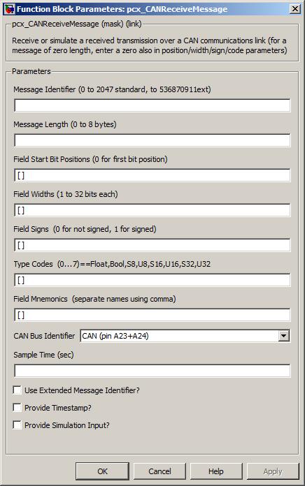
The unique can identifier of the message to be received.
Range: [0, 2047] if standard identifier
Range: [0, 536870911] if extended identifier
Value type: Integer Calibratable: No The number of data bytes to be received.
Range: [0, 8] bytes
Value type: Integer Calibratable: No A vector of bit numbers indicating the position at which each input Item begins in the CAN message. 0 corresponds to the least significant bit of data byte 0 of the message and 63 to the most significant byte of data byte 7 of the message, assuming these exist. For items whose bit length entry exceeds 7, the bit length must be one of: 0, 8, 16, 24, 32, 40, 48, 56.
Size: [1, 64] elements
Range: [0, 8], 16, 24, 32, 40, 48, 56 bit positions
Value type: Integer Calibratable: No A vector of bit lengths indicating the number of bits used to transmit each input Item. The following values are allowed: 1, 2, 3, 4, 5, 6, 7, 8, 9, 10, 11, 12, 13, 14, 15, 16, 24 and 32. Items of 8 bits or fewer may not be defined so as to straddle CAN byte boundaries.
Size: [1, 64] elements
Range: [1, 16], 24 or 32 bit width
Value type: Integer Calibratable: No A vector of 1 or 0 values. Corresponding data items for which this is set 1 are received as twos-complement signed numbers, or unsigned numbers otherwise.
Size: [1, 64] elements
Range: 0 or 1
Value type: Integer Calibratable: No This block provides one data field input for each element in Field Start Positions, as follows:
Table 5.2. CAN block type codes
Type code Simulink data type 0 real_T (single floating point type) 1 default boolean (boolean or real_T depending on current setting of Simulink Boolean logic signals setting) 2 signed 8 bit integer (int8_T) 3 unsigned 8 bit integer (uint8_T) 4 signed 16 bit integer (int16_T) 5 unsigned 16 bit integer (uint16_T) 6 signed 32 bit integer (int32_T) 7 unsigned 32 bit integer (uint32_T)
Value type: Integer Calibratable: No A string containing a comma-separated list of names with which to label the simulation input and CAN data output ports.
Value type: String Calibratable: No Which can bus the message will be received on.
Value type: Integer Calibratable: No The periodicity of the block execution.
Range: [0.001, 3600] seconds
Value type: Real Calibratable: No Use Extended Message Identifier?
If box is checked the 29 bit identifier is to be used, otherwise the 11 bit standard identifier is to be used.
Value type: Boolean Calibratable: No If selected then inport sim_timestamp and outport timestamp are made available.
Value type: Boolean Calibratable: No If selected then dummy inputs for each of the outport can message signals, such as
sim_signal_name, are provided by the block.Value type: Boolean Calibratable: No
Unused signals in a CAN message need not be specified in the Field Start Bit Positions parameter.
Not all OpenECU modules have both CAN buses populated (see Section 1.1, “ECU hardware reference documentation” for details about each device).
The signal data outports are updated any time a message is received as indicated by rx_trig_flag. If the error_flag outport is asserted due to a mismatch in message size, the data outports will contain potentially erroneous data from the incorrectly sized message. It is recommended that the application software latch the values of all CAN signals only when rx_trig_flag is set and error_flag is not set.
If the block shows unnamed outports, it is likely that one or more of the block fields is incorrect. Check the fields for mistakes and correct them.
The restrictions involving alignment of data items with 8 or more bits can be overcome by combining the smaller data items from the CAN message into larger data items using some Simulink math blocks, or by using the pcx_CANdb_ReceiveMessage block.
All data is unpacked in Motorola byte ordering (MS byte first, LS byte last). The order of byte unpacking can be overcome by combining the smaller data items from the CAN message into larger data items using some Simulink math blocks, or by using the pcx_CANdb_ReceiveMessage block.
Providing fewer than 8 entries in the Field Mnemonics parameter will result in some ports not being named. Providing greater than 8 entries in the Field Mnemonics parameter will result in corruption in the mask displayed on the block. This is a display artifact only and in both cases the port signals will still function as normal.