Configure a TLE8242-2 constant current output channel.
None (Main library). (See Section 2.3, “Licensed Features”.)
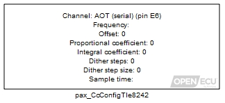
The current level is established with the pax_CcOutput block. Additional configuration specific to the TLE8242-2 is provided by this block. The configuration is applied at every block iteration.
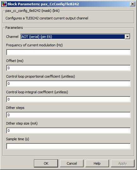
The channel pin for this constant current output.
Value type: List Calibratable: No Frequency of current modulation (Hz)
The desired frequency of the output. If the software cannot match the desired frequency, the frequency will be adjusted to as close a match as is possible.
Range: [10.5, 4000] Hz
Value type: Real Calibratable: Yes, offline and online The desired phase offset of the output relative to the TLE8242-2 phase sync signal. If the offset is initialised to a non zero value, then the outputs will hold until the phase sync signal is pulsed. The phase sync signal may be pulsed during runtime to syncronise outputs. If the software cannot match the desired pulse offset, the offset will be adjusted to as close a match as possible within 1/32 increments of the pulse period.
Range: [0, 31/32 of pulse period] ms
Value type: Real Calibratable: Yes, offline and online Control loop proportional coefficient (unitless)
The desired proportional coefficient of the PI control loop that determines the duty cycle of the constant current output. The supplied value is passed directly to the TLE8242-2 KP register without scaling applied.
Range: [0, 4095] unitless
Value type: Integer Calibratable: Yes, offline and online Control loop integral coefficient (unitless)
The desired integral coefficient of the PI control loop that determines the duty cycle of the constant current output. The supplied value is passed directly to the TLE8242-2 KI register without scaling applied.
Range: [0, 4095] unitless
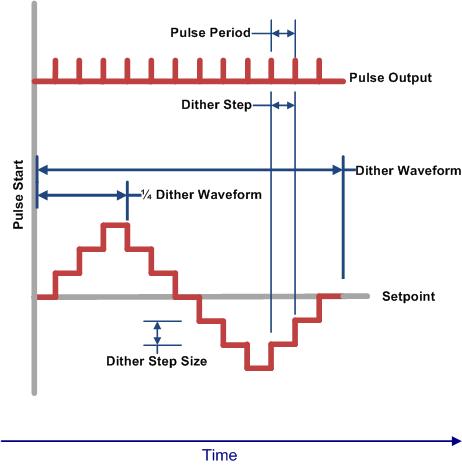
Value type: Integer Calibratable: Yes, offline and online The desired number of dither steps per 1/4 waveform. If the software cannot match the number of dither steps, the number of steps will be adjusted to as close a match as possible.
Range: [0, 31] steps per 1/4 dither cycle
Value type: Integer Calibratable: Yes, offline and online The desired dither step size. If the software cannot match the desired dither step size, the step size will be adjusted to as close a match as possible.
Range: [0, 500] mA
Value type: Integer Calibratable: Yes, offline and online The periodicity of the block execution.
Range: [0.001, 3600] seconds
Value type: Real Calibratable: No
The current level and configuration for a channel should be set in the same task to ensure data coherence.
The dither waveform is specified by the number of dither steps and the size of each step. Each output pulse advances the dither waveform by one step. The following diagram demonstrates the relationship between the pulse period, number of dither steps, and the dither step size.
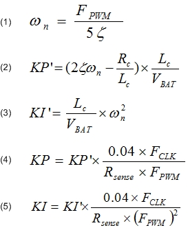
Each channel of the TLE8242-2 device includes a separate PI controller with programmable gain values KP and KI. The Infineon TLE7242 KI KP Application note describes a method to determine acceptable KP and KI values. A summary is included here; Please refer the the Infineon application note for additional details.
Acceptable KP and KI values may be determined by modeling the control system with a linear continuous time model.
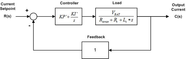
- Parameters required to calculate KP and KI
- VBAT
Supply voltage of the load.
- Rc
Resistance of the load.
- Lc
Inductance of the load measured at the pulse frequency.
- Rsense
Sense resistance value. This value is determined by the OpenECU hardware. It is 100 mR for all outputs.
- Fclk
Master clock frequency of the TLE8242-2 device. The frequency is set to 22 MHz by the OpenECU platform.
- FPWM
Pulse frequency of the output channel.
- Procedure to calculate KP and KI
- Determine Pulse Frequency
Set pulse frequency to the upper limit unless some constraint of the load requires it to be lower.
- Determine the damping ratio of the system
Start with 0.707. Increase toward 1 to reduce overshoot. Decrease to improve rise time. The damping ratio is denoted by zeta in the supplied equations.
- Determine the undamped natural frequency
Calculate according to equation 1. Decreasing will result in longer settling time and increased dither amplitude attenuation. Increasing will lead to poor matching of the linear model to the system.
- Calculate KP' and KI'
Calculate according to equations 2 and 3. If KP' is less than zero, then the pulse frequency is too low.
- Calculate KP and KI
Calculate according to equations 4 and 5. If KP or KI is greater than 4095, then the undamped natural frequency must be decreased.