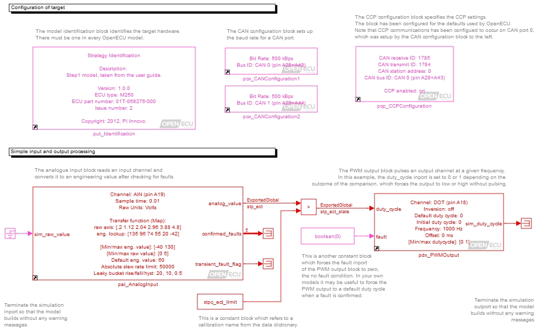
The model is now complete, but before its built, we can check it by updating the model. This also activates a number of visual indicators which help the user read the model, including library links and rate colouring.
To update the model (right click on the background and select the Update diagram menu item). Your model should now look like Figure 3.6, “Updated quick start model”.
- Library links
Each of the OpenECU blocks has a small icon of an arrow in the bottom left hand corner of the block display. This indicates that the block on the screen is a reference to the OpenECU library.
It is possible to break the library links but its very important that OpenECU blocks remain as library links. When they remain as library links, when the OpenECU software is updated, linked blocks are updated as well. If the link were broken, then the OpenECU software is updated, the unlinked block remains at the older version of OpenECU.
Warning
Mixing versions of OpenECU blocks in a model may lead to undefined results when the model is simulated or run on the target.
- Block and signal colouring
All of the blocks and signals have been coloured red (or magenta). This means that all the blocks run at the same rate and that the rate is the fastest in the model. If other rates were present in the model, Simulink would colour blocks and signals that run at those rates different colours.
Table 3.6. Simulink model colouring
Colour Description Red Fastest discrete sample time Green Second fastest discrete sample time Blue Third fastest discrete sample time Light blue Fourth fastest discrete sample time Dark green Fifth fastest discrete sample time Orange Sixth fastest discrete sample time Black Continuous blocks — these cannot be used with OpenECU. Cyan Blocks in triggered sub-systems — triggered sub-systems do not have a defined periodic rate and run sporadically when the trigger activates. Yellow A mixed or hybrid system which contains more than one rate. Purple/Magenta An invariant or constant — something which does not change during the run of the model. Simulink will try to optimise these items. The colouring is a very useful indicator of related tasks and helps the model designer break up the functionality between rates. As much as possible, functionality should be placed at the slowest rate possible to ensure that as much computing power on the ECU is made available.
- Exported global indication
Signals that need to be viewed while the model is running on the target must be defined as Exported Global. When the model is updated, Simulink explicitly shows the Exported Global item on the diagram and its a useful indicator in case you forgot to set the type.
- Vectors of signals
The analogue input block shows a vector of outputs as a thick line with the number 5 written beside it. This means the vector contains 5 elements. More information about each of those elements can be found in Section 5.1.6, “Analogue input — processed (pai_AnalogInput)”.
