Contents
System Modes
The ECU can run in one of two system modes: reprogramming mode and application mode. In reprogramming mode, processor(s) of the ECU can be reprogrammed with application software from a CCP calibration tool. In application mode, the ECU runs the programmed application software.
What is FEPS?
The Flash and EEPROM Programming Signal (FEPS) is used to signal the OpenECU firmware to enter reprogram mode instead of application mode during startup. FEPS is signaled by applying a voltage to the FEPS pin of the ECU. Most OpenECU targets support FEPS. Please refer to the technical specification to determine which pin is used for FEPS and which FEPS modes are supported.
Positive FEPS Mode
Positive FEPS mode is entered during start-up when the voltage on the FEPS pin exceeds the positive FEPS threshold. Positive FEPS mode attempts to use the CCP settings that are specified in the application that is programmed on the ECU. If these settings are not known, then it may be necessary to use Negative FEPS Mode instead.
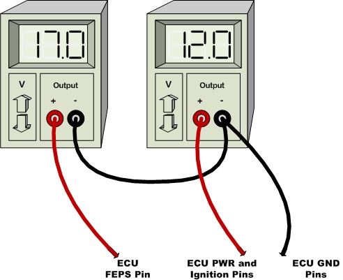
Reprogramming with positive FEPS using two power supplies
- Connect the ECU power, ground, and ignition wires to a power supply and set it to a voltage that is within the operating range of the ECU. Turn the power supply off.
- Connect the FEPS wire to another power supply and set it to a voltage that is greater than the positive FEPS threshold. Turn this supply on.
- Turn on the supply that is powering the ECU. Then, verify that the module is in positive
FEPS mode with the Flash Code Output
- Reprogram the ECU using the CCP settings that were specified in the application.
This diagram demonstrates the positive FEPS for an M220 ECU using two supplies.
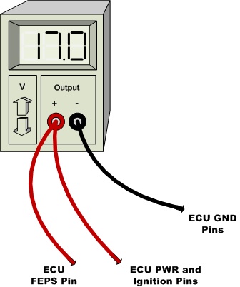
Reprogramming with positive FEPS using one power supply
If the positive FEPS threshold is within the operating range of the ECU, then it is possible to use a single supply. The following diagram demonstrates positive FEPS for an M220 ecu using one supply.
Negative FEPS Mode
Negative FEPS mode is entered during start-up when the voltage on the FEPS pin is less than the negative FEPS threshold. Negative FEPS mode will always use the default CCP settings.
Default Negative FEPS Mode CCP Settings:
CCP setting |
Default value |
CRO message identifier |
1785 |
DTO message identifier |
1784 |
Station address |
0 |
CAN bus identifier |
CAN 0 |
CAN bus baud-rate |
250kBps or 500kBps* |
* Refer to the User Guide to determine the default CAN baud-rate
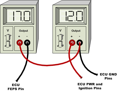
Reprogramming with negative FEPS using two power supplies:
- Arrange two power supplies such that the positive terminal of power supply (a) is connected to the negative terminal of power supply (b).
- Set the voltage of power supply (b) to the minimum operating voltage of the ECU and then connect the ECU power, ground, and ignition to the terminals of power supply (b)
- Set the voltage of power supply (a) such that the voltage between the positive and negative terminals is sufficient to provide the negative FEPS voltage at the negative terminal. Connect the FEPS wire to the negative terminal of power supply (a).
- Reset the ECU by turning power supply (b) off for a few seconds and then turning it
back on. Then, verify that the module is in positive FEPS mode with the Flash Code Output
- Connect the FEPS wire to the negative terminal of another power supply and set it to a voltage that is greater than the than the positive FEPS threshold. Turn this supply on.
- Turn on the supply that is powering the ECU. Then, verify that the module is in positive
FEPS mode with the Flash Code Output
- Reprogram the ECU using the default CCP settings
This diagram demonstrates the negative FEPS for an M220 ECU using two supplies.
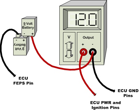
Reprogramming with negative FEPS using batteries:
Batteries can be substituted to produce the FEPS voltage at the FEPS pin. This diagram demonstrates the use of batteries to produce the negative FEPS voltage for an M220 ECU.


