CANape by Vector Informatik GmbH is a calibration tool that can communicate to a CCP compliant device. It provides facilities for calibration, data logging and display and can be used with OpenECU.
The following instructions are for version 8.0. Other versions may differ.
The instructions also assume that CANcaseXL is used. If another communications device is used, the user may need to deviate from these instructions.
Start CANape and you will be asked to accept a disclaimer. After this you will see the following:
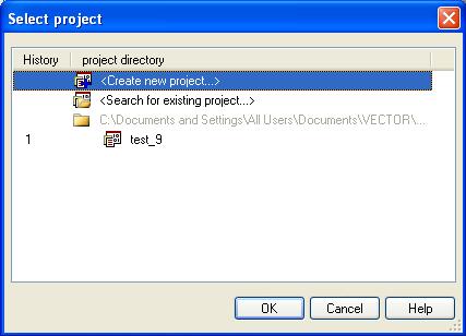
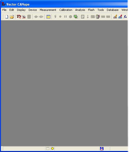
Select 'Create new project' and press 'OK'. You will then be asked for a project name. Enter a suitable name, click 'Next' and then browse to a suitable directory to save the project, click 'Next' and then 'Finish'. You should now see the following:
Select the menu option Device->New from database... and browse to where your model_name_canape.a2l file is located and select Open. If the device is connected correctly and configured with the appropriate baud rate then you should see no errors or warning. The a2l file contains the CAN configuration as set by the model. It also has the relevant information for the flash, cal and RAM locations. CANape will use these values with no further configuration input required from the user.
If CCP seed/key security is required for an operation, the DLL implementing the appropriate key-generation algorithm must be placed in the same directory as the CANape project. Note that CCP seed/key security is disabled by default in the model_name_canape.a2l file.
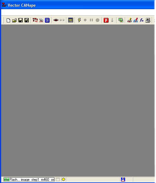
Having set up the project (and CCP security if required), select the menu option Flash->Download file to flash... and browse to your built application, e.g.,
step1_m460_image_small.hex. Depending on the size of the memory region to be flashed, it may be necessary to increase the flash clear timeout parameter in CANape.At the bottom left of the window the progress bar should be seen to advance until programming is complete.
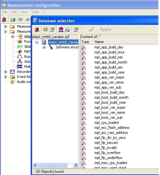
Next, select the menu option Measurement->Measurement configuration... and the following window will appear:
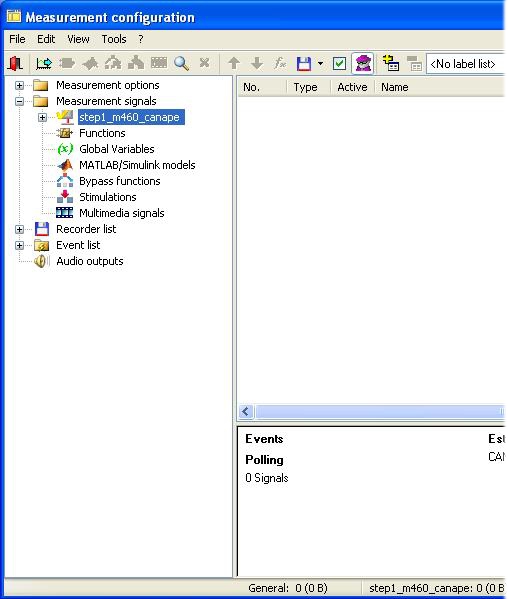
The Simulink model name should be visible in the left hand pane under 'Measurement signals'. Right click on the model name and select 'Insert signal' from the menu that appears. The Database selection window should then appear, listing all of the model signals and calibrateable values.
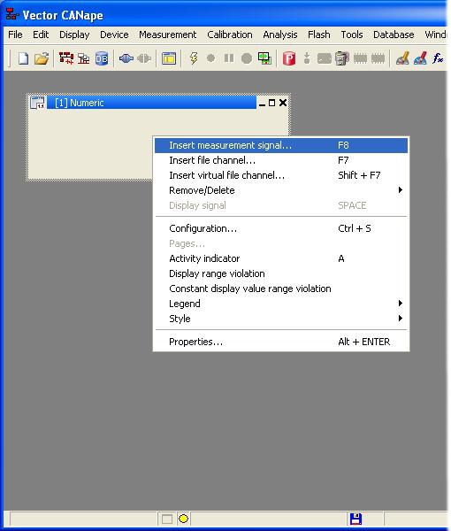
Double click on each signal of interest so that their text colour changes to blue. Close both windows and accept changes and you will return to the main window. Now select the menu option Display->Display windows->Numeric window, an empty numeric display will appear. Right click on this numeric display and select 'Insert measurement signal...' the following appears:
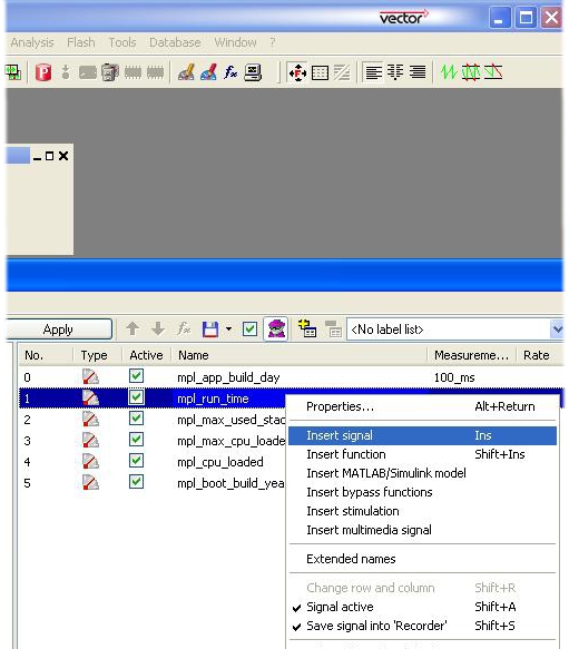
Next, right click and select 'Insert signal' on each parameter that you want to monitor in the numeric window
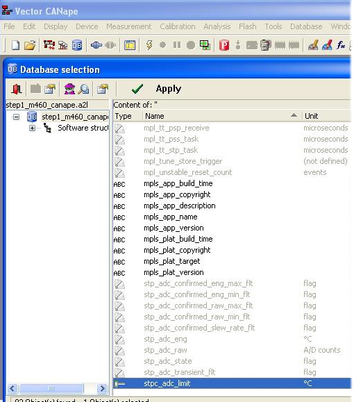
To access calibration values select the menu option Display->Calibration windows->Calibration window, then scroll down to find calibration parameters and select the ones that are required.
At this point, you have managed to connect Vector CANape to OpenECU,
downloaded the step1 application and viewed some signals in
real-time. Please refer to the Vector CANape user manual for more details
about how to use CANape.