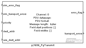
Construct the contents of a J1939 message, and attempt to transmit it.
None (Main library). (See Section 2.3, “Licensed Features”.)

When a J1939 message is to be transmitted, the block packs each of the signal inports into the message, as specified by the block mask parameters, and transmits the message.
Simulation value of the outport error_flag.
Value type: Boolean Calibratable: No Simulation value of the outport transport_errors.
Value type: Integer Calibratable: No The priority of the J1939 message to transmit.
Range: [0, 7]
Value type: Integer Calibratable: No

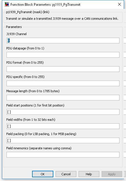
The logical J1939 channel on which to transmit. Must be a channel declared with a pj1939_ChannelConfiguration block.
Value type: Integer Calibratable: No The pdu datapage value of the PGN of the J1939 message to transmit.
Range: 0 or 1
Value type: Integer Calibratable: No The pdu format value of the PGN of the J1939 message to transmit.
Range: [0, 255]
Value type: Integer Calibratable: No The pdu specific value of the PGN of the J1939 message to transmit. If the PDU format parameter is less than 240, then this parameter is not available for editing and does not form part of the PGN.
Range: [0, 255]
Value type: Integer Calibratable: No The length of the data bytes in the message to transmit. Maximum size is the smaller of maximum range or buffer size.
Range: [0, 1785]
Value type: Integer Calibratable: No A vector of bit numbers indicating the start position of each field in the CAN message.
Field start positions correspond to the message data bytes as follows:
Data byte Bit number LS MS LS 1 8 7 6 5 4 3 2 1 2 16 15 14 13 12 11 10 9 ... ... 1785 14279 14278 14277 14276 14275 14274 14273 14272 MS MS LS where byte 1 corresponds to the first received data byte in the first CAN message for the J1939 message. This numbering scheme matches the J1939 specification but differs from the existing CAN blocks. Although this may cause some confusion when both blocks are used in the same model, it will help reduce mistakes when using the J1939 blockset with the J1939 specification of message contents.
Value type: Integer Calibratable: No A vector of bit lengths indicating the number of bits allocated to each field.
Range: [1, 32] bits
A field which starts at bit 5 and has 10 bits of width is identified as follows:
Data byte Bit number 1 8 7 6 5 - - - - 2 - - 14 13 12 11 10 9 Value type: Integer Calibratable: No A vector of zero or one values, corresponding to each field. Fields for which this is set 1 are transmitted as MS packing, or LS packing otherwise.
Range: 0 or 1
J1939 message fields are generally packed LS byte first, so the field which starts at bit 5 and has 10 bits of width, would be interpreted as:
MS LS Data byte 2 Data byte 1 - - - - - - 14 13 12 11 10 9 8 7 6 5 s s s s s s x x x x x x x x x x where 'x' is the corresponding bit taken from the J1939 message data bytes, and 's' is the sign extension of the data. In this case, bit 14 may be considered the sign bit, if the data in the J1939 message data is signed.
However, if the J1939 message field was packed MS byte first, the bits would be interpreted as:
MS LS Data byte 1 Data byte 2 - - - - - - 6 5 14 13 12 11 10 9 8 7 s s s s s s x x x x x x x x x x where 'x' is the corresponding bit taken from the J1939 message data bytes, and 's' is the sign extension of the data. In this case, bit 6 may be considered the sign bit, if the data in the J1939 message data is signed.
Value type: Integer Calibratable: No A string containing a comma-separated list of names with which to label the message field inports.
Range: 0 or 1
Value type: String Calibratable: No
Unused fields in a J1939 message need not be specified in the Field start positions parameter (bits in unused fields are set to 1 for transmission).
If the block shows unnamed inports, or if the field inports are not shown, it is likely that one or more of the block's parameter fields is incorrect. Check the parameter fields for mistakes and correct them.
The following example illustrates the least significant (LS) and most significant (MS) byte ordering in J1939 messages. Given two parameters:
MS LS Byte 1 2 Parameter 1 (hex) 10 11 Parameter 2 (hex) 20 21 the first parameter is packed into the J1939 message in LS byte format, starting at bit 0, is 16 bits wide and unsigned, and the second parameter is packed in MS byte format, starting at bit 32, and is also 16 bit wide and unsigned.
MS LS Byte 1 2 3 4 5 6 Message (hex) 11 10 FF FF 20 21 Parameter 1 has been packed using LS byte formatting. The LS byte of 0x1011 (0x11) has been packed into the LS byte of its position within the message (byte 1), and the MS byte of 0x1011 (0x10) has been packed into the MS byte of its position within the message (byte 2).
Parameter 2 is packed using MS byte formatting. The LS byte of 0x2021 (0x21) has been packed into the MS byte of its position within the message (byte 6), and the MS byte of 0x2021 (0x20) has been packed into the MS byte of its position within the message (byte 5).
Bytes 2 and 3 are not used and are therefore set with all bits at 1.