Extract the data contents from a received J1939 message.
None (Main library). (See Section 2.3, “Licensed Features”.)
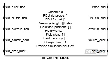
When a matching J1939 message to this block is received, the block unpacks the message contents into individual signals, as specified by the block mask parameters, and provides them as outports.
Warning
The PCX feature takes precedence over the PJ1939 feature. If you configure the PCX feature to receive a J1939 frame, the PJ1939 feature will not see the frame, and it will not be processed by the platform. This especially causes problems when receiving J1939 DM14 'Boot Load' commands.
Simulation value for the outport error_flag.
Value type: Boolean Calibratable: No Simulation value for the outport rx_trig_flag.
Value type: Boolean Calibratable: No Simulation value for the outport overrun_flag.
Value type: Boolean Calibratable: No Simulation value for the outport source_addr.
Value type: Integer Calibratable: No Simulation value for the outport dest_addr.
Value type: Integer Calibratable: No The simulation value for the outport timestamp. Available only if the mask parameter Provide timestamp is selected.
Value type: Integer A set of simulation inports for the corresponding outports fields. Available if there is at least one field and the parameter Provide simulation input? is selected.
Value type: Integer Calibratable: No
Set to 1 if some error has occurred which prevents CAN reception, or 0 otherwise. Errors which prevent reception are: CAN bus detected as bus-off, or the length of the received J1939 message does not match the Message length parameter.
Range: 0 or 1
Value type: Boolean Calibratable: No Set to 1 if the block has detected reception of the J1939 message since the last iteration of this block, set to zero otherwise.
Range: 0 or 1
Value type: Boolean Calibratable: No Set to 1 if the block has detected reception of the same J1939 message more than once between iterations of this block.
Range: 0 or 1
Value type: Boolean Calibratable: No The source J1939 network address of the message.
Range: [0, 253] or 255
Value type: Integer Calibratable: No The destination J1939 network address of the message.
Range: [0, 253] or 255
Value type: Integer Calibratable: No The time when the last valid message was received. Strictly this gives the time when the message was assembled from the possibly multiple CAN packets, and has a resolution of 50 ms. The timestamp is a free-running microsecond timer that wraps to zero approximately every 70 minutes. Available only if the mask parameter Provide timestamp is selected.
Range: [0, 4294967295] us
Value type: Integer An outport for each field specified in the block.
Value type: Real Calibratable: No
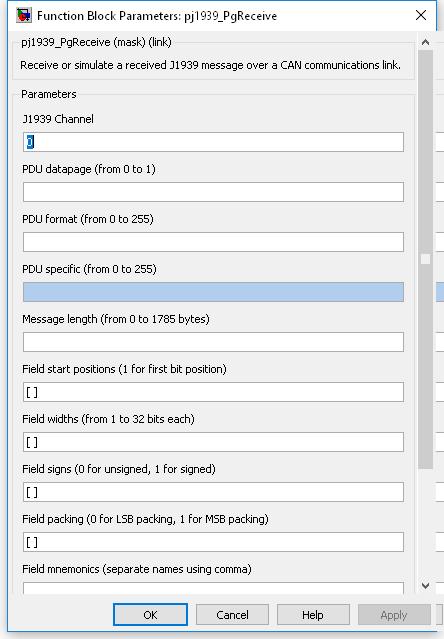
The logical J1939 channel on which the message will arrive. Must be a channel declared with a pj1939_ChannelConfiguration block.
Value type: Integer Calibratable: No The pdu datapage value of the PGN of the J1939 message to receive.
Range: 0 or 1
Value type: Integer Calibratable: No The pdu format value of the PGN of the J1939 message to receive.
Range: [0, 255]
Value type: Integer Calibratable: No The pdu specific value of the PGN of the J1939 message to receive. If the PDU format parameter is less than 240, then this parameter is not available for editing and does not form part of the PGN.
Range: [0, 255]
Value type: Integer Calibratable: No The length of the data bytes in the message to be received.
Range: [0, 1785]
Value type: Integer Calibratable: No A vector of bit numbers indicating the start position of each field in the CAN message.
Field start positions correspond to the message data bytes as follows:
Data byte Bit number LS MS LS 1 8 7 6 5 4 3 2 1 2 16 15 14 13 12 11 10 9 ... ... 1785 14280 14279 14278 14277 14276 14275 14274 14273 MS MS LS where byte 1 corresponds to the first received data byte in the first CAN message for the J1939 message. This numbering scheme matches the J1939 specification but differs from the existing CAN blocks. Although this may cause some confusion when both blocks are used in the same model, it will help reduce mistakes when using the J1939 blockset with the J1939 specification of message contents.
Value type: Integer Calibratable: No A vector of bit lengths indicating the number of bits allocated to each field.
Range: [1, 32] bits
A field which starts at bit 5 and has 10 bits of width is identified as follows:
Data byte Bit number 1 8 7 6 5 - - - - 2 - - 14 13 12 11 10 9 Value type: Integer Calibratable: No A vector of zero or one values, corresponding to each field. Fields for which this is set 1 are received as twos-complement signed numbers, or unsigned numbers otherwise.
Range: 0 or 1
Value type: Integer Calibratable: No A vector of zero or one values, corresponding to each field. Fields for which this is set 1 are received as MS packing, or LS packing otherwise.
Range: 0 or 1
J1939 message fields are generally packed LS byte first, so the field which starts at bit 5 and has 10 bits of width, would be interpreted as:
MS LS Data byte 2 Data byte 1 - - - - - - 14 13 12 11 10 9 8 7 6 5 s s s s s s x x x x x x x x x x where 'x' is the corresponding bit taken from the J1939 message data bytes, and 's' is the sign extension of the data. In this case, bit 14 may be considered the sign bit, if the data in the J1939 message data is signed.
However, if the J1939 message field was packed MS byte first, the bits would be interpreted as:
MS LS Data byte 1 Data byte 2 - - - - - - 6 5 14 13 12 11 10 9 8 7 s s s s s s x x x x x x x x x x where 'x' is the corresponding bit taken from the J1939 message data bytes, and 's' is the sign extension of the data. In this case, bit 6 may be considered the sign bit, if the data in the J1939 message data is signed.
Value type: Integer Calibratable: No A string containing a comma-separated list of names with which to label the simulation field inports and message field outports.
Range: 0 or 1
Value type: String Calibratable: No If selected then create simulation inports (sim_fields) for each of the outport message signals (fields).
Value type: Boolean Calibratable: No If selected then inport sim_timestamp and outport timestamp are made available.
Value type: Boolean Calibratable: No The periodicity of the block execution.
Range: [0.001, 3600] seconds
Value type: Real Calibratable: No
Unused fields in a J1939 message need not be specified in the Field start positions parameter.
If the block shows unnamed outports, or if the field outports are not shown, it is likely that one or more of the block's parameter fields is incorrect. Check the parameter fields for mistakes and correct them.
The following example illustrates the least significant (LS) and most significant (MS) byte ordering in J1939 messages. The message is received as follows:
MS LS Byte 1 2 3 4 5 6 Message (hex) 11 10 FF FF 20 21 where the first parameter is in LS byte format, starts at bit 0, is 16 bits wide and unsigned, and the second parameter is in MS byte format, starts at bit 32, and is also 16 bit wide and unsigned.
Parameter 1 is unpacked using LS byte formatting giving 0x1011. The LS byte is unpacked from the LS byte of its position within the message (byte 1) giving 0x11, and the MS byte is unpacked from the MS byte of its position within the message (byte 2) giving 0x10.
Parameter 2 is unpacked using MS byte formatting giving 0x2021. The LS byte is unpacked from the MS byte of its position within the message (byte 6) giving 0x21, and the MS byte is unpacked from the MS byte of its position within the message (byte 5) giving 0x20.