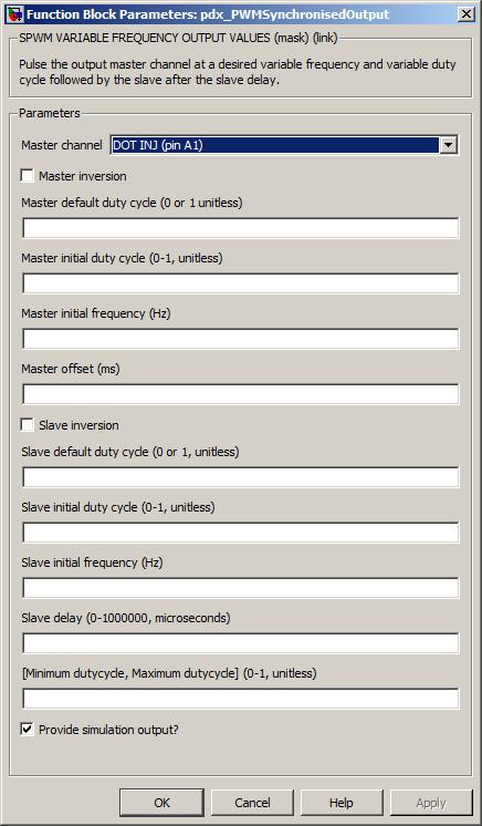
Pulse two output channel pins at a variable frequency and variable duty cycle. The second output channel is synchronised to the first.
None (Main library). (See Section 2.3, “Licensed Features”.)
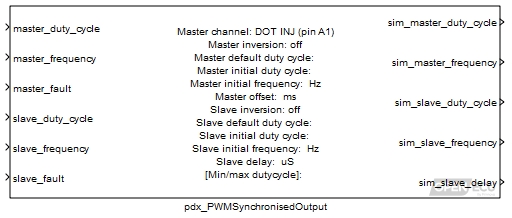
The synchronised PWM output block causes two channel output pins to oscillate with independent frequency and duty cycle. The duty cycle is the High time divided by the Cycle time for a given channel.
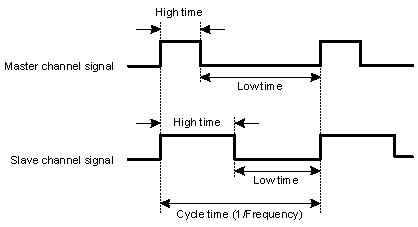
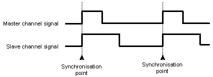
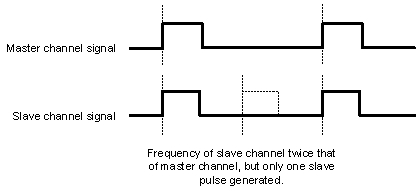
The slave channel is generated relative to the master channel pulse (in this instance, both the master and slave channels are generated with the same frequency).
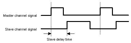
The slave pulse can be delayed relative to the master pulse by setting the parameter Slave delay to a non-zero value.
In all cases, only one pulse per cycle is generated by both the master and slave channels. For instance, if the frequency of the slave channel was twice that of the master channel, only one pulse would be generated by the slave channel.
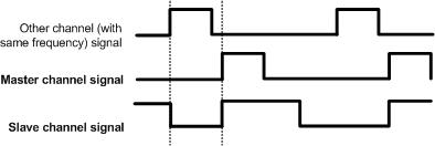
The Master channel output (and thus the slave) can be offset from other PWM channels of the same frequency. The Master offset parameter is used to delay the start of the PWM cycle, so that the PWM pulse will not occur at the same time as other PWM signals of the same frequency.
This block calculates the master output duty cycle as:
output master duty cycle = Minimum duty cycle + (Maximum duty cycle - Minimum duty cycle) * master_duty_cycle
and the slave output duty cycle as:
output slave duty cycle = Minimum duty cycle + (Maximum duty cycle - Minimum duty cycle) * slave_duty_cycle
For a given channel, if the output duty cycle is 0, the output channel state is set low and does not oscillate. If the output duty cycle is 1, the output channel state is set high and does not oscillate.
If the inport master_fault input is non-zero, then the output master duty cycle is set to the mask parameter Master default duty cycle. Similarly for the output slave duty cycle.
Ratio of the high time to the signal cycle time for the master channel.
Range: [0, 1] duty-cycle
Frequency of the master channel signal.
Range: [1, 10000] Hz (for M250, M460 targets)
Set to 1 to force the block to use the default master frequency and master duty cycle for the master channel, 0 otherwise.
Range: 0 or 1
Ratio of the high time to the signal cycle time for the slave channel.
Range: [0, 1] duty-cycle
Frequency of the slave channel signal.
Range: [1, 10000] Hz (for M250, M460 targets)
Set to 1 to force the block to use the default slave frequency and slave duty cycle for the slave channel, 0 otherwise.
Range: 0 or 1
Only used in simulation. this outport is set to the calculated duty cycle for the master channel.
Range: [0, 1] duty-cycle
Only used in simulation. this outport is set to the calculated frequency for the master channel.
Range: [1, 10000] Hz (for M250, M460 targets)
Only used in simulation. this outport is set to the calculated duty cycle for the slave channel.
Range: [0, 1] duty-cycle
Only used in simulation. this outport is set to the calculated frequency for the slave channel.
Range: [1, 10000] Hz (for M250, M460 targets)
Only used in simulation. this outport is set to the calculated frequency for the slave channel.
Range: [0, 1000000] microseconds
The master channel for this block. The slave channel is automatically assigned.
If selected, the final master duty cycle is set to 1 minus the output master duty cycle, otherwise the final master duty cycle is the same as the output master duty cycle.
This is the final duty cycle of the channel when inport master_fault is set. The duty cycle is mapped directly to the output channel and is not inverted by parameter Master inversion.
Range: 0 or 1 duty-cycle
The duty cycle of the channel signal before the block has first been executed. This duty cycle is inverted if the mask parameter Master inversion is set to 1.
Range: [0, 1] duty-cycle
The frequency of the channel signal before the block first iterates.
Range: [1, 10000] Hz (for M250, M460 targets)
The offset of the master (and hence the slave) channel output.
Range: Target dependent
Target Range M110 Not supported M220 Not supported M221 Not supported M250 [0, 2000] ms M460 [0, 2000] ms M461 Not supported M670 Not supported Value type: Real Calibratable: No If selected, the final slave duty cycle is set to 1 minus the output slave duty cycle, otherwise the final slave duty cycle is the same as the output slave duty cycle.
This is the final duty cycle of the channel when inport slave_fault is set. The duty cycle is mapped directly to the output channel and is not inverted by parameter Slave inversion.
Range: 0 or 1 duty-cycle
The duty cycle of the channel signal before the block has first been executed. This duty cycle is inverted if the mask parameter Slave inversion is set to 1.
Range: [0, 1] duty-cycle
The frequency of the channel signal before the block first iterates.
Range: [1, 10000] Hz (for M250, M460 targets)
The time delay between synchronisation of the master and slave channel. The slave pulse is started Slave delay microseconds after the master pulse starts.
Range: [0, 1000000] microseconds
Must be in the range 0 to (Maximum duty cycle - 0.1).
Range: [0, 0.9] duty-cycle
Must be in the range (Minimum duty cycle + 0.1) to 1.0.
Range: [0.1, 1] duty-cycle
Tick to enable outports sim_master_duty_cycle, sim_master_frequency, sim_slave_duty_cycle, sim_slave_frequency and sim_slave_delay.
Value type: Boolean Calibratable: No
If the pulse for the slave channel extends through the synchronisation point, then the master and slave channel signals become undefined. Most likely is that the master channel continues to generate a PWM signal and the slave channel goes low, but this is not guaranteed under all conditions.
To avoid an inconsistent update to the output, the low-lying driver (based on code from the silicon manufacturer) buffers new parameters before applying them. This results in a delay of two or three PWM cycles between the model updating the frequency or duty cycle and the effect being seen in the output waveform.