Drives the H-Bridge channel pins according to a mode at a variable frequency and duty-cycle.
None (Main library). (See Section 2.3, “Licensed Features”.)
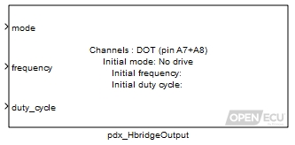
The H-Bridge output block drives a load connected between the two ECU pins in the desired mode. Four modes are provided allowing the H-Bridge output to have no drive (all switches open), brake (high-side switches closed), forward or reverse (one side is connected to high-side while the other is PWM'ed to ground at a programmable frequency and duty-cycle).
Warning
To avoid unexpected behavior, H-bridges should be set to NO DRIVE mode before flashing the ECU. This can be done by commanding the actuators to NO DRIVE any time the engine is not turning.
The duty-cycle used in forward and reverse mode is defined as the proportion of time where the load is driven (low-side switch is grounded).
The block supports 0% and 100% duty cycles.
Note
Some of the PWM output channels do not produce an accurate waveform when the duty cycle is either very small (e.g., 0.5%) or very large (e.g., 99.5%). All H-bridge output channels cope with 0% and 100% duty cycles correctly.
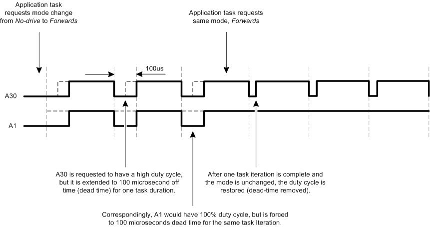
For the M250 target specifically, in order to avoid shoot-through and damage to the ECU when the mode switches, a 100us dead-time is inserted in the PWM signal for one task cycle at the beginning of mode-transition. Additionally, this dead-time insertion will only occur if the duty cycle that is commanded has a low time of less than 100us. For this reason, it will not be possible to command a 100% duty cycle during mode-transition for one task period. See diagram below for further detail.
Mode in which the H-bridge will operate.
Range: [0, 3] respectively for No Drive / Brake / Forward / Reverse.
Value type: Integer Frequency of the PWM signal
Range: [0.5, 10000] Hz (for M220, M250 and M670 targets)
Value type: Real Ratio of the drive time to the signal cycle time.
Range: [0, 1] duty-cycle
Value type: Real Calibratable: No
The pair of input pins sourcing the signal to measure.
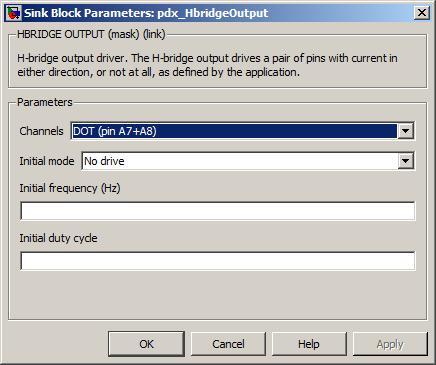
Value type: List Calibratable: No The initial mode of operation used whilst the application is initialising.
Range: [No Drive, Brake, Forward, Reverse] (for M220, M250 and M670 targets)
Value type: List Calibratable: No The initial frequency used whilst the application is initialising.
Range: [0.5, 10000] Hz (for M220, M250 and M670 targets)
Value type: Real Calibratable: Yes, offline The initial duty cycle used whilst the appplication is initialising.
Range: [0, 1] duty-cycle
Value type: Real Calibratable: Yes, offline