Control an angular digital output.
None (Main library). (See Section 2.3, “Licensed Features”.)
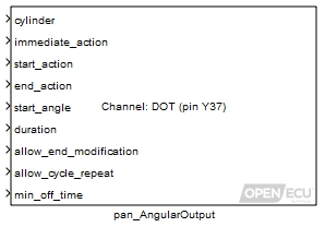
The pan_AngularOutput block allows an application to control an output in the angular domain in a fairly generic way by specifying start and end actions on a digital output pin state. The start actions are always specified to occur at a start angle, while the end actions are specified to occur at some duration after the start angle. The duration can be either an angle or a time depending on the output mode selected. Note that the output mode is a fixed property of the output that is specified by the corresponding pan_AngularOutputConfig block. Possible actions are setting the pin-state to active or inactive, toggling the state or leaving the state unchanged.
In addition to controlling the output in the angular domain, the block allows an immediate action to be specified. This allows a relatively crude level of purely time-based control to occur at the resolution of the block task time. An example application might be to control an output using this immediate action before crank synchronisation, and then use the angular control once crank sync had been attained.
Some illustrations of the block in action are given below.


Multiple instances of the pan_AngularOutput block associated with a given channel are allowed, to allow the output to be controlled more easily both in the angular and time domain. However a single instance of the pan_AngularOutputConfig block must exist for each channel used.
Note
Care must be taken when using multiple instances of the pan_AngularOutput block on the same channel, since they will potentially be in competition.
The start angle is interpreted either relative to crank-zero, or relative to the TDC-firing angle of a specified cylinder number. The specified start event will then occur at the next such start angle to occur. For a two-stroke engine (as specified by the pan_EngineConfig block), the start angle is interpreted modulo 360 degrees. For a four-stroke engine, the start angle is interpreted modulo 360 degrees in half engine synchronisation mode, and modulo 720 degrees in full engine synchronisation mode.
When the ECU is in neither half or full engine synchronisation mode, the output can be scheduled but will not be driven as the engine position will be unknown. If engine synchronisation is lost, then the output pin state is set to the value specified in the Stall action) mask parameter of the corresponding pan_AngularOutputConfig block. This also determines the initial output state before the current block has ever run.
The pan_AngularOutput supports the scheduling of a sequence of up to six events at a time. Each event has a different start action, end action, start angle, and duration, specified as a mux of values to the block inports. The sequence of events can be modified at any time during the engine cycle, to add, remove, or modify existing events. The updated values will take effect on the current engine cycle if the start angle of the next scheduled pulse has not been reached when the block is iterated, or on the next engine cycle if the start angle has already been reached for the current engine cycle. If the duration of an event is set to zero, then it will be skipped.
The sequence of events specified by the pan_AngularOutput can be repeated automatically every engine cycle by setting the allow_cycle_repeat inport to one. If the allow_cycle_repeat inport is set to zero then a single sequence of events will be scheduled, and a further block iteration is required to generate further events. If the pan_AngularOutput iterates before the next scheduled event has started, and the start angle of the new data is still in the future, then the new data will supersede the previous data. If the start angle of the new data is in the past, and the previous data is in the future, then the previous data will be used for only the next event instead of scheduling the event for the next engine cycle. The preference being that it is better to keep the previously scheduled event, than to skip the event for the current engine cycle.
Each index in the mux of values is treated as a separate event. If the block iterates while an event is underway and the data for the current event in the mux of values is modified, then the behaviour is determined by the allow_end_modification inport value. If this is zero, then the data will be buffered and take effect on the next instance of that event. On the other hand, if the allow_end_modification inport value is one, then the end of the event will be updated according to the newly provided duration and end_action values (and the start_action and start_angle values are ignored). If the newly provided duration has already elapsed, then the end_action is applied immediately. (Note that in this case it will be applied immediately after any immediate_action that has been specified.)


If the duration for an event is zero, then that event will be skipped for the schedule of events. If the duration for all events in the schedule are set to zero, then at the start_angle of the event in the first index of the schedule, a single action will be performed corresponding to the result of applying the start_action followed by the end_action. For example, if both actions specify that the output pin state should be toggled, then no change to the pin state will occur. If an update occurs when an event is underway with duration of zero and allow_end_modification set to one, then the newly specified end_action is applied immediately.
The possible values for the inports immediate_action, start_action, and end_action are:
Table 6.3. Angular digital output pin actions
| Value | Description |
|---|---|
| 0 | Turn-off - the output pin will be modified to the non-driven state. |
| 1 | Turn-on - the output pin will be modified to the driven state. |
| 2 | Toggle - the output pin will be toggled. |
| 3 | No-action - the output pin will not change driven state. |
If two events in a schedule overlap, the first pulse will be terminated at the start angle of the next pulse with a single action corresponding to the result of applying the end_action of the first event followed by the start_action of the next event. The schedule will then continue normally with the duration of the next event, resulting in the correct timing of the next event from that event's start_angle.

If an event start_action occurs within the min_off_time after the end_action of a previous event, the second event will be delayed to ensure the min_off_time is maintained between the two events. The min_off_time can be set to zero to prevent the subsequent pulse from being delayed.

This determines how the start_angle is to be interpreted. If zero is passed, then the start_angle inport is interpreted relative to crank zero degrees. If a number between 1 and the number of cylinders is passed, then the start_angle is interpreted relative to that cylinder's TDC-firing angle.
Range: 0 or [1, n] where n is the number of cylinders specified by the pan_EngineConfig block.
Value type: Integer The action to apply immediately (i.e. when the block iterates) to the output state, as specified by Table 6.3, “Angular digital output pin actions”.
Value type: Integer A vector of actions to apply to the output state at the angle specified by start_angle, as specified by Table 6.3, “Angular digital output pin actions”. This vector may contain up to six elements and must be the same width and have the same ordering as the end_action, start_angle, and duration vectors.
Value type: Integer A vector of actions to apply to the output state after the specified duration has elapsed since the start_angle, as specified by Table 6.3, “Angular digital output pin actions”. This vector may contain up to six elements and must be the same width and have the same ordering as the start_action, start_angle, and duration vectors.
Value type: Integer A vector of requested start angles for the beginning of the output event. The interpretation of this angle is determined by the value passed to the cylinder inport. The value of the angle is folded to the range modulo 360° or 720° as appropriate as explained above. This vector may contain up to six elements and must be the same width and have the same ordering as the start_action, end_action, and duration vectors.
Range: [-720, 720] ° Resolution: at least 0.1 degrees
Value type: Real A vector of either angles or times depending on the Mode specified in the instance of the pan_AngularOutputConfig block that exists for this channel. When the Mode is Angle-Angle, then the durations are angles in degrees; if it is Angle-Time then the durations are times in milliseconds. The duration specifies when after the start_angle to apply the pin action specified by the end_action. This vector may contain up to six elements and must be the same width and have the same ordering as the start_action, end_action, and start_angle vectors.
Range: [0, 360000] ° or [0, 2000] milliseconds
Value type: Real A flag that applies only when an event is currently underway. Set to one to update the duration and end_action information immediately. Set to zero to buffer the data to be used on the next instance of the event.
Value type: Boolean Set to one to repeat the schedule of events, set to zero to schedule events once only.
Value type: Boolean The minimum time between events, delaying the start of subsequent events if necessary.
Range: [0, 5] milliseconds
Value type: Real