The following instructions assume the user is using a supported version. These instructions were transcribed against a supported version but it may be that these instructions match other versions of the tool.
They also assume that an ATI Vision Hub is used. If another communications device is used, the user will need to deviate from these instructions.
Install ATI vision, the installer may reboot your machine. Once windows is restarted, it will detect new USB hardware (assuming the hub is plugged in: if not, plug it in).
Ask windows to install the USB hardware software from the "device software" directory located where you just installed ATI vision, e.g., c:\program files\Accurate Technologies\ati vision\device software.
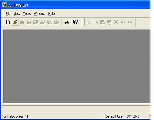
Start Vision and you will be presented with a window similar to the following:
Next, you must create a project to details how ATI Vision will communicate with the OpenECU device.
Create a new project using the menu option File->New, then select Project.
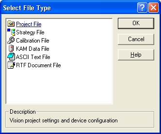
and save it somewhere on your hard-disk (here, it has been saved using the name "example_project").
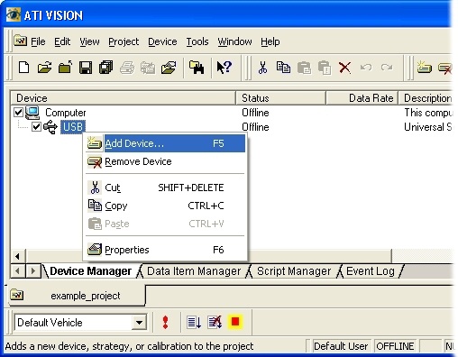
Next, add a device by right clicking on the Computer item and selecting "Add Device..."
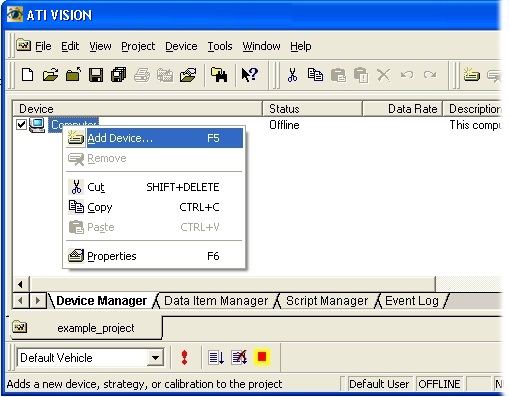
Select USB port and in the subsequent dialog, accept all the defaults and select OK.
Next, add a device by right clicking on the USB item and selecting "Add Device..."
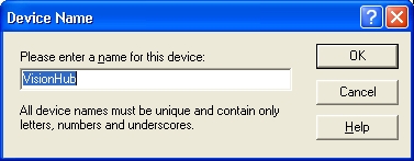
Select VISION Network Hub in the subsequent dialog and select OK.
Accept the default hub name and in the subsequent dialog properties defaults by selecting OK.
Next, add another device by right clicking on the VisionHub item and selecting "Add Device..."
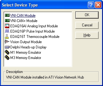
Select a VNI CAN device type, accept the default name and in the subsequent dialog, accept the defaults by selecting OK.
Next, add another device by right clicking on the VNICAN item and selecting "Add Device..."
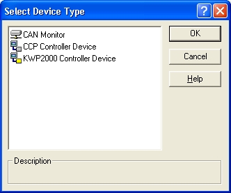
Select the CCP Controller Device, accept the default name and in the subsequent dialog, accept the defaults by selecting OK. This has told the Vision tool that you will be communicating to a CCP compatible device over CAN via the Vision Hub connected to the PC via a USB cable.
Next, you must create a strategy file to hold both the calibration data and program data. Select File->New, then Strategy File.
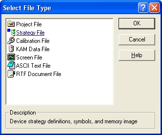
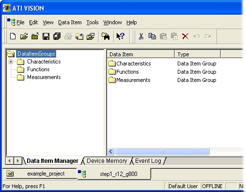
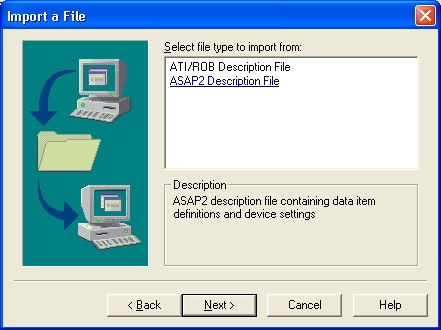
The main Vision window will change and you will be presented with the import wizard. Select the ASAP2 description file item.
For the
step1example, select thestep1_tool_vision.a2lfile from the location where you built it (note that the following diagrams show an older version of the step1 application calledstep1_r12_g800).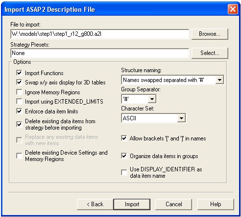
It is important to keep the "Strategy Presets" text box clear and to tick the "Delete existing data items from before importing" check-box. This ensures that the memory and CCP settings are taken from the ASAP2 file and that subsequent imports of the same strategy will clear out previous ASAP entries before loading the latest.
Click Import to read in the ASAP2 file, then click on the More button.
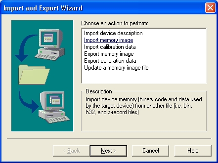
Select import memory image, then select Motorola S-record File, then browse and select the
step1_image_small.s37file from the place where you built it.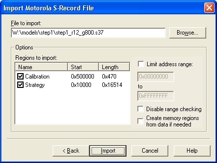
Select Import, then Finish. The Wizard dialog box now closes.
Note
You must now save this strategy (menu option File->Save) and change back to the project file by clicking on the "example_project" tab at the bottom of the Vision window.