When connecting to a single OpenECU for the first time, the tool and OpenECU settings will probably use the default CCP settings (as described in Table 5.3, “CCP defaults”). The example which follows assumes the default CCP settings.
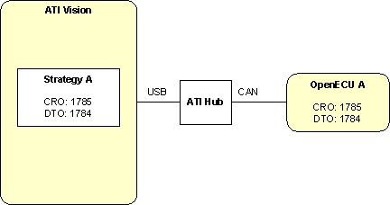
The above diagram shows ATI Vision with a single strategy using the default CCP settings. A similarly configured OpenECU is connected to ATI Vision via the CAN bus to the Vision Hub, and from the Hub to the PC via a USB cable. Your setup may vary depending on what equipment you have (for instance, you may have two ATI Hubs but the overall concept of configuring the additional OpenECU's remains).
When a second OpenECU is first required, a second application will be built into a second strategy which must use different CCP settings from the first strategy. The tool settings may follow the example default settings for two OpenECUs.
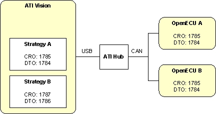
The diagram shows ATI Vision with two strategies: strategy A using the default CCP settings (as in the single OpenECU example above); strategy B using different CCP settings. The CCP settings distinguish between the two OpenECUs. Two OpenECUs are connected to the Hub allowing ATI Vision to communicate with both.
As this is the first time the second OpenECU has been connected to the CAN bus, it uses the default CCP settings. When the user selects strategy B in Vision, Vision uses the strategy B CCP CAN identifiers but there is no OpenECU with matching CCP settings. Without any response Vision shows the OpenECU for strategy B as offline.
Follow this procedure to program OpenECU B with strategy B for the first time:
Disconnect OpenECU A from the CAN bus. This prevents OpenECU A from interfering with communications to OpenECU B.
Right click on strategy B and select Open File. The screen will change.
Select File -> Properties and change to the Device Settings tab in the new dialog.
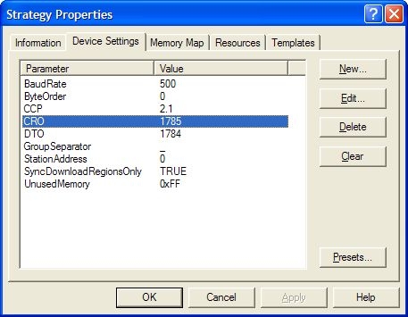
Change the CRO CAN identifier to 1785 and the DTO CAN identifier to 1784, then select File -> Save.
Change back to the Project tab (so you can see both strategy A and strategy B), right click on strategy B and select Reload File. This brings the CRO and DTO changes into strategy B.
Your setup is now configured as:
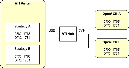
If strategy B is selected, ATI Vision will show OpenECU B as online.
Reprogram OpenECU B with strategy B (see Section 2.3, “ATI Vision” and Section 4.5, “Programming an ECU” for more).
Once reprogrammed, power cycle OpenECU B. ATI Vision will show OpenECU B as offline.
Right click on strategy B and select Open File. Select File -> Properties, change to the Device Settings tab in the new dialog, change the CRO CAN identifier to 1787 and the DTO CAN identifier to 1786, then select File -> Save.
Change back to the Project tab (so you can see both strategy A and strategy B), right click on strategy B and select Reload File.
Your setup is now configured as:
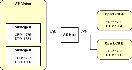
Reconnect OpenECU A to the CAN bus. Select strategy A to communicate with OpenECU A, or select strategy B to communicate with OpenECU B.
Note
The above procedure is equally applicable when reprogramming a single OpenECU to new CCP settings. Ensure there is only one OpenECU connected to the CAN bus, build the application with the new CCP settings, import into Vision, adjust the CCP settings in Vision to that of the connected OpenECU, reprogram the OpenECU and reset it, then adjust the CCP settings in Vision to that of the application.