How should I use the ECU pin electrical current monitors?

The output circuit current monitors, such as M670 “Monitor (c) (pin XL4)” are analog inputs to the microprocessor, which are sampled at a fast periodic rate which is fixed by the OpenECU Platform. The important point to note is the sampling of the analog input is not synchronized in any way with the activity of the related output pin. So, if you have Pin XL4 configured in your application as a PWM output with variable frequency and duty, the current through the pin will be measured at fast but unsynchronized moments in time, relative to the PWM pulses happening on the pin. Therefore, we expect some samples to correspond to moments when the output was being driven, and other samples may have been taken while the output was inactive.
Because of this periodic, asynchronous sampling which is inherent to these monitors, many customers choose to implement peak-detector logic on the current monitor signal, in order to reveal the peak current observed during PWM activation. For instance, you can read the current monitor in a 1ms application task, and hold the maximum observed sample value, clearing the result every 500ms (or whatever interval you choose) to permit decreases in current to be updated.
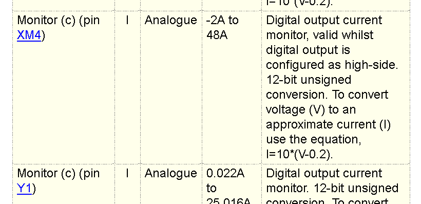
There is a transfer function to convert the analog voltage of the current monitor input into units of ampere, as described in the ECU’s Technical Specification document. For M670 Pin XL4, the nominal current is defined as I=10*(V-0.2).

There is also a small bias voltage expected in current monitor hardware circuits- this is the same principle as the DC offset observed while using inductive current probes with oscilloscopes, where the offset must be manually trimmed when no current is flowing, before an accurate measurement can be performed. So for the current monitors in the ECU, you should include logic in your application to sample and save the steady-state value of each current monitor, storing the result at a moment when your application is not driving the output pin. This becomes an additional zero-offset you should then always apply to the current monitor transfer function.
Finally, current monitors for outputs that can be put in inactive states (such as H-bridge outputs) will report invalid values (such as zero volts) when the corresponding output is disabled. So for the H-bridge example, current monitor values should be ignored when the H-bridge output is in “no-drive” mode. Also for H-bridge, during “Forward” or “Reverse” drive modes, only the current monitor result from the low-side of the H-bridge will be valid, and the current monitor for the side being driven to battery should be ignored.
So in summary, to use the current monitor for an output pin such as an H-bridge for peak current detection in your app, you will want to include the following types of logic:
- Analog input from the pin current monitor
- Nominal transfer function (from Tech Spec)
- Output-commanded-off (ie: 0% duty in Forward Drive mode) current value zero-point learning
- Time-windowed peak value detector
- Result switch-to-zero when the output is being commanded inactive (ie: No-Drive)
