Release 2.9.0 (r2020-1)
Copyright © 2020 Pi Innovo
13-Apr-2020
Table of Contents
- Overview
- 1. Blockset summary
- 1.1. Target ECU identification and configuration
- 1.2. Input/output signal processing — time based
- 1.3. Input/output signal processing — engine/angular based
- 1.4. Communications — CAN
- 1.5. Communications — CCP
- 1.6. Communications — ISO 15765 (J1979, KWP-2000, UDS)
- 1.7. Communications — SAE J1939
- 1.8. Communications — SPI
- 1.9. OBD Infrastructure — Fault support
- 1.10. OBD Infrastructure — PID support
- 1.11. OBD Infrastructure — Freeze Frame support
- 1.12. OBD Infrastructure — In-Use Performance Ratio support
- 1.13. Adaptive parameters
- 1.14. Utilities
- 1.15. Versioning
- 1.16. Operating system
- 1.17. Operating system — Memory checks
- 1.18. Operating system — Timing
- 1.19. Tool support — MATLAB and Simulink Coder
- 1.20. Tool support — C compilers
- 2. Blockset target support
- A. Contact information
This document provides an overview of the 203 blocks and related functionality that make up the OpenECU blockset.
- Target ECU identification and configuration [more details on 5 blocks]
All applications start by identifying the target ECU. Once identified, the application can configure the behaviour of the ECU using the blocks provided with OpenECU.
- Input/output signal processing — time based [more details on 25 blocks]
OpenECU provides Simulink blocks to access time based electrical signals on the ECU connector pins, and electrical signals internal the ECU. Input blocks range from simple analogue input measurement to more complex quadrature decoding, and output blocks range from simple digital outputs to more complex stepper motor signal generation.
- Input/output signal processing — engine/angular based [more details on 52 blocks]
OpenECU provides Simulink blocks to access engine based electrical signals on the ECU connector pins. Support is provided for two and four stroke engines, crank and cam trigger wheel decoding, overall engine position information including analogue input measurement relative to the engine position, port and direct injection, coil spark generation, knock signal processing and angular digital output control.
- Communications
OpenECU provides Simulink blocks to receive and transmit individual CAN frames, and Simulink blocks to handle higher level protocols including CCP (for reprogramming, data logging and real-time calibration on the fly), SAE J1939 (for heavy duty and off road applications) and ISO 15765 (for light duty applications utilising J1979, KWP2000 and UDS). The blockset also provides support for Vector CANdb files (which describe networks, CAN messages and CAN signals in detail).
- Communications — CAN [more details on 9 blocks]
OpenECU provides Simulink blocks to configure and query the status of CAN buses, as well as blocks to receive and transmit CAN frames.
- Communications — CCP [more details on 5 blocks]
The CAN Calibration Protocol (CCP) is a CAN based messaging system specified by ASAM and designed to work with calibration tools for application development purposes. At the end of a successful model build, OpenECU will generate an ASAP-2 file which describes the variables and calibratable data from the model. A compliant calibration tool reads the ASAP-2 file and communicates to the ECU using CAN messages to access or change the model data using the CCP protocol (ASAP-1b) in real-time.
- Communications — ISO 15765 (J1979, KWP-2000, UDS) [more details on 4 blocks]
The ISO messaging protocol is a CAN based messaging system designed to pass information between vehicle network ECUs in real-time. OpenECU is designed to communicate with an external diagnostic scan or test tool using a subset of ISO 15765-2 based protocols, including SAE J1979 (ISO 15031-5, “OBD2”), KeyWord Protocol 2000-3 (KWP2000, ISO 14230-3), and Unified Diagnostic Services (UDS, ISO 14229-1).
- Communications — SAE J1939 [more details on 34 blocks]
The J1939 messaging protocol is a CAN based messaging system designed to pass information between vehicle network ECUs in real-time. OpenECU is designed to communicate with an external diagnostic scan or test tool using a subset of SAE J1939 protocols, including part 21 for single and multi-packet messages, part 73 for diagnostics requirements, part 71 for vehicle application messages, and part 81 for network management.
- Communications — SPI [more details on 1 block]
The platform uses the SPI protocol to communicate between the main microprocessor and various other peripheral devices on the ECU. This is all handled internally by the OpeECU platform; however, it does provide an interface to report faulty communications with such devices to the application.
- OBD Infrastructure
OpenECU's diagnostic support has been designed to meet both CARB and EURO diagnostics requirements and communicate with diagnostic scan tools according to both heavy duty (SAE J1939) and passenger car (ISO 15765) protocols. Diagnostic support is aimed at vehicles which have to comply with 2010 and beyond legislation (e.g. EURO6).
- OBD Infrastructure — Fault support [more details on 13 blocks]
OpenECU provides blocks to support Diagnostic Trouble Codes (DTCs). DTCs are the basic building blocks of OpenECU's diagnostic support. There are multiple standards for the fault information to follow as well as choices for its life-cycle depending on whether it is emissions-related or permanent and the legislation being followed. These details are selected within the Simulink definition block for each DTC and allow the user to configure the system for various aspects of diagnostic legislation.
- OBD Infrastructure — PID support [more details on 2 blocks]
OpenECU provides Simulink blocks to support Parameter Identifiers (PID). A PID is used to access the current value of an application parameter by a diagnostic scan tool. The access includes reading the parameter and if enabled over-riding the parameter. If the parameter is a non-volatile PID, this value can be written to non-volatile memory and retained across power cycles.
- OBD Infrastructure — Freeze Frame support [more details on 3 blocks]
OpenECU provides Simulink blocks to support freeze frames. DTCs can have an associated freeze frame that is stored when the fault occurs. The application may specify several different types of freeze frame for use with different DTCs. The various freeze frame definitions may include more or less data to be captured when a fault occurs.
- OBD Infrastructure — In-Use Performance Ratio support [more details on 6 blocks]
OpenECU provides Simulink blocks to support diagnostic monitors, tests and performance ratios. A complete emissions related diagnostic system will have a have a set of diagnostic monitors to check the performance of each of the various components on a vehicle. These diagnostic monitors are in turn made of a series of diagnostic tests. The individual tests may be performed continuously, for example checking the range of an analogue input or the state of an output signal. Alternatively the tests may be classed as non-continuous which means that they can only be performed when the vehicle is in a certain operating state, for example checking the performance of a catalyst or the EGR sub-system.
- Adaptive parameters [more details on 4 blocks]
OpenECU provides Simulink blocks that allow the application to adjust scalars, 1-d and 2-d maps while the application runs on the target ECU. An example might be learning the range of a component as mechanical wear changes the dimensions of the component, such as a throttle body.
The adaptive data defined by these blocks can be stored in non-volatile memory across power cycles.
- Utilities [more details on 6 blocks]
OpenECU provides a set of blocks for utility purposes, covering map look-up and interpolation, simple signal conditioning and ECU reset information.
- Versioning [more details on 13 blocks]
For configuration management purposes, it can be useful to restrict the version of OpenECU software that can be used when editing and building an application model. The OpenECU blockset provides a flexible way to specify the allowable versions.
For configuration management and debugging purposes, it can be useful to know the versions of software running on an ECU are compatible. The blockset library provides a way to retrieve the version numbers of the various software components running on an ECU.
- Operating system [more details on 9 blocks]
OpenECU provides a fixed-priority, pre-emptive, Real-Time Operating System to schedule application tasks and OpenECU tasks. When Simulink Coder generates code for the application model, it gathers functionality that runs at the same rate into tasks. The priority of each application task is assigned according to model rate.
- Operating system — Memory checks [more details on 4 blocks]
Non-volatile memory devices, like Flash, hold the ECU's firmware and application software, whilst volatile memory devices, like RAM, hold the ECUs working data. Failures in memory devices can result in undefined behaviour from the software. Memories are continuously checked for errors. Recoverable errors are handled and reported to the application. Unrecoverable errors cause the ECU to reset.
- Operating system — Timing [more details on 2 blocks]
Real time applications, like those developed for OpenECU, often need to time events or durations, at different resolutions. The blockset library provides two mechanisms to manipulate time: using the Simulink task timers which have a course time resolution matching the fastest model rate; and using the ECU processor's timers which have a much finer resolution.
- Tool support — MATLAB and Simulink Coder [more details on 4 blocks]
To support switching between auto-coders, the blockset library provides a set of blocks which switch between the different configuration sets. Simulink configuration sets contain options for a specific auto-coder. Currently, building models against the RTW (GRT RTMODEL) and RTW (EC) auto-coders is supported.
- Tool support — Calibration
The blockset supports calibratables and displayables are defined in a data dictionary, set up per model. OpenECU has specific support for some versions of ATI Vision, ETAS INCA and VECTOR CANape but can also generate generic ASAP2 information for inclusion into any ASAP2 compliant calibration tool.
- Tool support — Reprogramming
OpenECU supports reprogramming of any ECU via CCP or UDS programming protocols, but can also support J1939 if required (please contact Pi for this option). Programming can be prevented by unauthorised users through a security exchange that the application can define.
- Tool support — C compilers [more details on 2 blocks]
OpenECU provides support for several different compilers to suit the application needs. Support includes some versions of the Wind River Diab and GNU GCC compilers.
All applications start by identifying the target ECU. Once identified, the application can configure the behaviour of the ECU using the blocks provided with OpenECU.
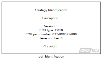 |
Model identification (put_Identification) The model identification block specifies which ECU hardware to target and information to be recorded in the built model and calibration image. |
Some ECUs have non-standard functionality, such as software select-able electrical filtering for inputs or software select-able configuration for accelerometer measurements, and special support is provided for those capabilities.
 |
Configuration M250 (pcfg_Config_M250) Specific configuration for the M250 target ECU. |
 |
Configuration M460 (pcfg_Config_M460) Specific configuration for the M460 target ECU. |
 |
Configuration M670 (pcfg_Config_M670) Specific configuration for the M670 target ECU. |
Each ECU contains information about itself, such as a unique serial number or the manufacturer's batch build number. This information can be retrieved and used by software tools to identify the ECU, perhaps for in-field diagnostics or end-of-line programming.
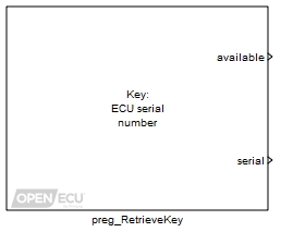 |
Retrieve registry key (preg_RetrieveKey) Given a key, search the registry for the corresponding data. |
OpenECU provides Simulink blocks to access time based electrical signals on the ECU connector pins, and electrical signals internal the ECU. Input blocks range from simple analogue input measurement to more complex quadrature decoding, and output blocks range from simple digital outputs to more complex stepper motor signal generation.
Input signal measurements cover analogue inputs (such as throttle position), digital inputs (such as brake switch), frequency and PWM measurement (such as smart alternators), quadrature decoding (such as position, direction and speed of rotating shafts) and SENT decoding (defined by SAE J2716).
Each block includes a channel selection, specifying the channel pin name for easy reference. Most blocks include additional parameters that can be modified by the application in real-time (such as the frequency of PWM output generation), or additional parameters that can be modified by a calibration tool.
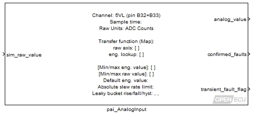 |
Analogue input — processed (pai_AnalogInput) Read an analogue input channel, convert to engineering units and fault check. |
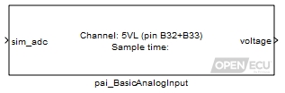 |
Analogue input — basic (pai_BasicAnalogInput) Read an analogue input channel and convert to a voltage. |
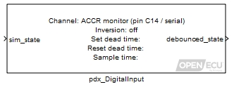 |
Digital input (pdx_DigitalInput) Output the state of a digital input pin after debounce logic. |
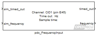 |
Frequency input (pdx_FrequencyInput) Output the last measured frequency. |
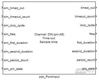 |
PWM input measurement (pdx_PwmInput) Measure a PWM signal and derive the frequency and duty cycle. |
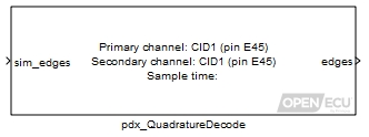 |
Quadrature decode input (pdx_QuadratureDecode) Output the number of edges sensed from the quadrature encoder since the last time the block iterated. |
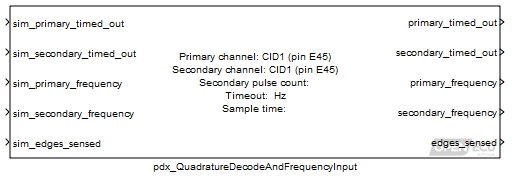 |
Quadrature decode and frequency input measurement (pdx_QuadratureDecodeAndFrequencyInput) Output the number of edges sensed from the quadrature encoder since the last time the block iterated. Output the last measured frequency of the primary and secondary channels. |
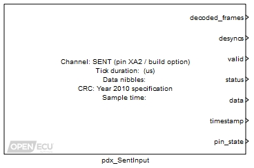 |
SENT input (pdx_SentInput) The SENT input block (Single Edge Nibble Transmission) decodes a SENT sensor's transmission pulses according to SAE J2716 Jan 2010, making available the sensor's status and data information. |
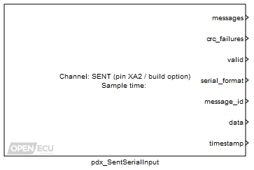 |
SENT input — serial data (pdx_SentSerialInput) The SENT serial input block (Single Edge Nibble Transmission) decodes a SENT sensor's transmission pulses according to SAE J2716 Jan 2010, making available the sensor's short or enhanced serial data. |
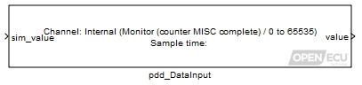 |
Digital data input (pdd_DataInput) Read the value of a digital data input. |
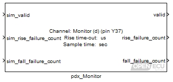 |
Digital output monitor (pdx_Monitor) Monitor the response of a digital output. |
Output signal generation covers constant current generation (such as valves), digital outputs (such as lamps), pulse-width modulation (PWM, such as fan speed control), synchronised PWM (such as current spread) and H-bridge control (such as throttle motors).
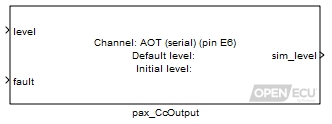 |
Constant current output (pax_CcOutput) Drive the output channel pin to a given current. |
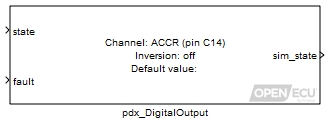 |
Digital output (pdx_DigitalOutput) Set the output channel pin high or low. |
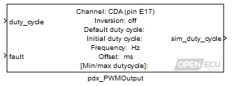 |
PWM output — fixed frequency (pdx_PWMOutput) Pulse the output channel pin at a fixed frequency and variable duty cycle. |
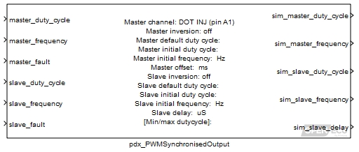 |
PWM output — variable frequency, synchronised (pdx_PWMSynchronisedOutput) Pulse two output channel pins at a variable frequency and variable duty cycle. The second output channel is synchronised to the first. |
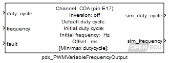 |
PWM output — variable frequency (pdx_PWMVariableFrequencyOutput) Pulse the output channel pin at a variable frequency and duty cycle. |
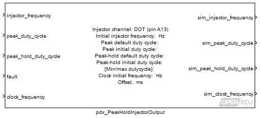 |
Peak and hold injector output (pdx_PeakHoldInjectorOutput) Control a peak and hold injector. |
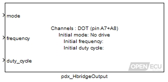 |
H-Bridge output (pdx_HBridgeOutput) Drives the H-Bridge channel pins according to a mode at a variable frequency and duty-cycle. |
For ECUs that use the TLE8242 device for constant current generation, the application can fine tune the device's behaviour and take additional measurements.
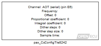 |
Constant current output — configuration for TLE8242-2 outputs (pax_CcConfigTle8242) Configure a TLE8242-2 constant current output channel. |
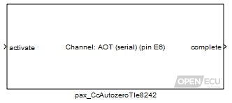 |
Constant current output — autozero for TLE8242-2 channels (pax_CcAutozeroTle8242) Command a TLE8242-2 constant current channel to autozero. |
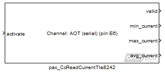 |
Constant current output — monitor for TLE8242-2 channels (pax_CcReadCurrentTle8242) Reports current measurement for a TLE8242-2 channel. |
Some ECUs have support for wide band oxygen sensors (often referred to as UEGO sensors, for Universal Exhaust Gas Oxygen, or linear lambda oxygen sensor) generate an indication of the oxygen content in the exhaust gas mixture.
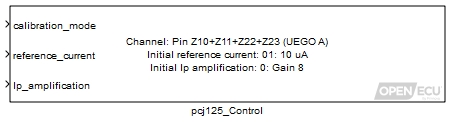 |
UEGO sensor control — CJ125 device (pcj125_Control) Update internal configuration of CJ125 devices. |
Some ECUs have an overall output driver control signal or a common high-side control signal that can be used to turn on or off groups of output pins. The overall control signal is controlled with a specific block.
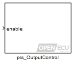 |
Output control (pss_OutputControl) Enable or disable the output drivers. |
All ECUs have methods to directly or indirectly diagnose electrical faults. Usually these electrical fault signals (monitors) can be read using the same blocks for reading analogue and digital inputs but there are some specialised blocks for dealing with some types of electrical faults.
 |
Over-current trip reset (pss_OvercurTripReset) Provide access to the over-current trip latch reset functionality. |
 |
Over current trip reset and diagnostic enable (pss_OvercurTripReset_DiagnEnable) Provide access to the over-current trip latch reset functionality and high side (safety switch) diagnostic enable switch. |
OpenECU provides Simulink blocks to access engine based electrical signals on the ECU connector pins. Support is provided for two and four stroke engines, crank and cam trigger wheel decoding, overall engine position information including analogue input measurement relative to the engine position, port and direct injection, coil spark generation, knock signal processing and angular digital output control.
An engine control application starts by configuring the engine position input signals. The blockset includes support for a variety of crank and cam encoding wheels for two and four stroke operation, and can support cam-less four stroke operation where the application determines the engine cycle from air intake pressure or engine acceleration measurements.
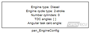 |
Engine configuration (pan_EngineConfig) Specify information about the engine configuration. |
 |
Crank wheel — configuration (pan_CrankWheelConfig) Configure a crankshaft wheel encoder input channel. |
 |
Crank wheel — extended configuration (pan_CrankWheelConfigExt) Configure the extended parameters for decoding a crankshaft wheel encoder, including missing tooth detection, noise rejection and stall detection. |
 |
Cam wheel — configuration (pan_CamWheelConfig) Configure a camshaft wheel encoder input channel. |
The application can then run engine control logic on a time and/or angle basis. To achieve this, the OpenECU blockset provides information about the crank position.
 |
Crank wheel — movement (pan_CrankWheelMovement) Determine whether a crankshaft wheel is moving or not. |
 |
Crank wheel — synchronisation (pan_CrankWheelSync) Retrieve the synchronisation state for a crankshaft wheel. |
 |
Crank wheel — tooth (pan_CurrentCrankTooth) Retrieve the current crankshaft wheel tooth identifier. |
 |
Crank wheel — angle (pan_CurrentCrankAngle) Retrieve the current crankshaft wheel angle. |
 |
Crank wheel — speed (pan_CrankWheelSpeed) Calculate the rotational speed of a crankshaft wheel. |
For some specialised application, the OpenECU blockset can determine the phasing between the primary crank wheel and multiple secondary crank wheels.
 |
Crank wheel — secondary phase angle (pan_CrankSecondaryPhase) Retrieve the phase angle of a secondary crankshaft wheel relative to the primary wheel. |
OpenECU provides information about the decoded state of the crank wheel signal both to support crank wheels with multiple synchronisation points, e.g., 60-1-2-3, and to diagnose integration between the application and the crank wheel sensor.
 |
Crank wheel — sync point last (pan_CrankWheelSyncPointLast) Retrieve information about the last successfully decoded crankshaft wheel sync point. |
 |
Crank wheel — sync point next (pan_CrankWheelSyncPointNext) Provide information about the next crank region to the ECU. |
 |
Crank wheel — sync point trigger (pan_CrankWheelSyncPointTrigger) Generate an asynchronous function-call trigger for each detected crankshaft wheel sync point. |
To help with configuring OpenECU with one or more crank sensors, the OpenECU blockset provides information about the processed crank sensor input and how the crank signal is being decoded.
 |
Crank wheel — digital input (pan_CrankWheelDigitalInput) Reads the immediate digital state of a crankshaft wheel input pin. |
 |
Crank wheel — decoding (pan_CrankWheelDecodeState) Retrieve the last error detected and current state of decoding a crankshaft wheel input. |
The OpenECU blockset provides information about the cam position.
 |
Cam wheel — digital input (pan_CamWheelDigitalInput) Reads the immediate digital state of a camshaft wheel input pin. |
 |
Cam wheel — movement (pan_CamWheelMovement) Determine whether a camshaft wheel is moving or not. |
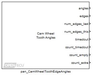 |
Cam wheel — tooth edge angles (pan_CamWheelToothEdgeAngles) Retrieve the measured angles of camshaft wheel teeth (rising edges, falling edges or both). |
The application takes the crank and cam wheel information, determines the overall engine position and provides that information to the ECU. In turn, the ECUs adjusts input and output schedules based on angle.
 |
Engine synchronisation — declare mode (pan_EngineDeclareSync) Declare synchronisation with the overall engine position. |
At any point, the application can declare loss of engine synchronisation. In turn, the ECU turns off most angular input and output processing, which includes turning off injector and spark outputs.
 |
Engine synchronisation — declare loss of synchronisation (pan_EngineLoseSync) Force loss of engine synchronisation. |
The OpenECU blockset provides information about the overall engine position.
 |
Engine synchronisation (pan_EngineSync) Retrieve the current engine synchronisation mode. |
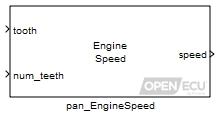 |
Engine speed (pan_EngineSpeed) Calculate the rotational speed of the engine. |
 |
Engine tooth (pan_CurrentEngineTooth) Retrieve the current engine tooth identifier from the primary crankshaft position. |
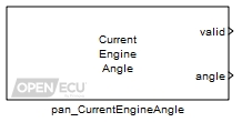 |
Engine angle (pan_CurrentEngineAngle) Retrieve the current engine angle. |
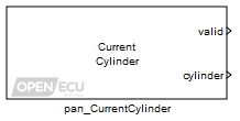 |
Engine cylinder (pan_CurrentCylinder) Retrieve the current cylinder identifier. |
The application may optionally configure and read a number of analogue inputs relative to the overall engine position.
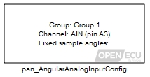 |
Analogue input — angular, configuration (pan_AngularAnalogInput_Config) Configure an analogue input channel to sample on an angular basis. |
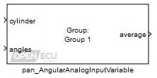 |
Analogue input — angular, variable relative angle (pan_AngularAnalogInputVariable) Retrieves analogue input samples taken relative to a cylinder's TDC-firing angle. |
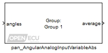 |
Analogue input — angular, variable absolute angle (pan_AngularAnalogInputVariableAbs) Retrieves analogue input samples taken relative to crank zero degrees. |
The application may optionally configure and read the results of knock signal processing. Knock signals are sampled, filtered and integrated at specific engine positions determined by the application. The application can vary the filter characteristics within allowable limits.
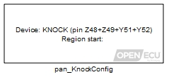 |
Knock configuration (pan_KnockConfig) Configure the parameters used to sample a knock sensor. |
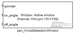 |
Knock detection window (pan_KnockDetectionWindow) Schedule the angular region used to process a knock sensor signal for a cylinder. |
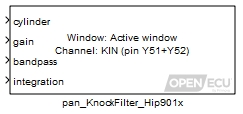 |
Knock filter — HIP901x (pan_KnockFilter_Hip901x) Update the scheduled knock signal filtering parameters for a cylinder for the HIP901x family of engine knock signal processors. |
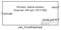 |
Knock feedback (pan_KnockFeedback) Retrieve the result of the last processed knock signal for a cylinder. |
The application may optionally configure and drive a number of direct injectors. Support is included for driving more than one injector per cylinder and making late fuel adjustments which compensate for rapid changes in fuel rail pressure.
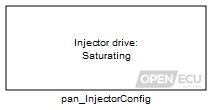 |
Injection configuration — multiple outputs (pan_InjectorConfig) Configure a set of injector channels for fueling an engine. |
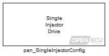 |
Injection configuration — single output (pan_SingleInjectorConfig) Configure a single injector output channel for fueling an engine. |
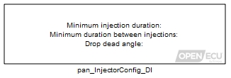 |
Injection configuration — direct injection (pan_InjectorConfig_DI) Configures constraints for direct injection. |
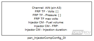 |
Injection configuration — fuel rail pressure compensation (pan_InjectorCompConfig_DI) Configure the volume to duration conversion for direct injection. |
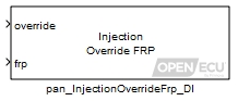 |
Injection direct — fuel rail pressure override (pan_InjectionOverrideFrp_DI) Override the fuel rail pressure input used for direct injection. |
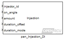 |
Injection direct — set schedule (pan_Injection_DI) Update the requested schedule of direct injections for one injector channel. |
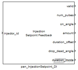 |
Injection direct — setpoint feedback (pan_InjectionSetpoint_DI) Read back direct injection parameters for a given injector. |
 |
Injection direct — event feedback (pan_InjectionFeedback_DI) Report feedback for injection events that have already occurred. |
The application may optionally configure and drive a number of port injectors. Support is included for driving more than one injector per cylinder and making late fuel adjustments which compensate for rapid changes in engine speed. Support is included for driving injectors when synchronisation with the crank wheel has been achieved but synchronisation with the cam wheel is pending to improve engine starts.
|
|
Injection configuration — multiple outputs (pan_InjectorConfig) Configure a set of injector channels for fueling an engine. |
|
|
Injection configuration — single output (pan_SingleInjectorConfig) Configure a single injector output channel for fueling an engine. |
 |
Injection port — initial fuel pulse (pan_InitialInjection_PI) Specify the duration of the initial injection (the priming fuel pulse). |
 |
Injection port — set schedule (pan_Injection_PI) Set the injector pulse schedule for a cylinder. |
 |
Injection port — update injection schedule (pan_UpdateInjection_PI) Update the port injection schedule for a cylinder. |
 |
Injection port — setpoint feedback (pan_InjectionSetpoint_PI) Read back port injection parameters for a given injector. |
 |
Injection port — event feedback (pan_InjectionFeedback_PI) Report feedback for port injection events that have already occurred. |
The application may optionally configure and drive a number of spark coils. Support is included for driving spark coils with and without cam synchronisation.
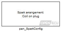 |
Spark configuration (pan_SparkConfig) Configure a set of spark channels for running an engine. |
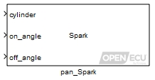 |
Spark (pan_Spark) Update the requested schedule of spark pulses for one spark channel. |
 |
Spark feedback (pan_SparkFeedback) Retrieve spark pulse information for a given cylinder. |
The application may optionally configure and drive a number of angular digital outputs.
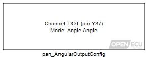 |
Digital output — angular configuration (pan_AngularOutputConfig) Configures basic information for a angular digital output on a particular channel. |
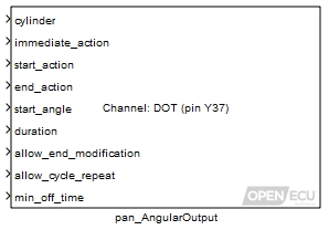 |
Digital output — angular digital (pan_AngularOutput) Control an angular digital output. |
OpenECU provides Simulink blocks to configure and query the status of CAN buses, as well as blocks to receive and transmit CAN frames.
An application that will receive or transmit CAN messages starts by configuring the CAN buses to use.
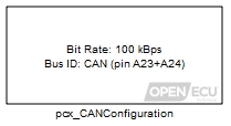 |
CAN configuration (pcx_CANConfiguration) Specify the configuration for a CAN bus. |
Blocks to pack and transmit CAN messages, or receive and unpack CAN messages, are provided. The blocks can work on the data byte message contents directly by specifying bit start position, length, byte ordering, etc., or can work at a higher level with CANdb files using message and signal names.
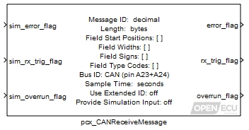 |
CAN receive message (pcx_CANReceiveMessage) Receive a CAN message and unpack the message contents. |
|
|
CAN transmit message (pcx_CANTransmitMessage) Pack a CAN message with data then transmit it. |
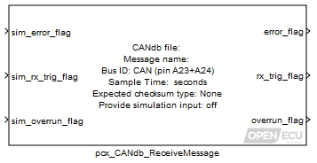 |
CANdb message receive (pcx_CANdb_ReceiveMessage) Receive a CAN message, the identifier and contents of which are defined by a Vector CANdb file. |
|
|
CANdb transmit message (pcx_CANdb_TransmitMessage) Transmit a CAN message, the identifier and contents of which are defined by a Vector CANdb file. |
Those blocks output diagnostic information about messaging, such as the last time-stamp of a received CAN message or the number of times an application has requested a CAN message is transmitted compared to how many times the CAN message was sent.
In addition to individual message diagnostic information, the OpenECU blockset provides a block to report status information (e.g., bus off or error passive).
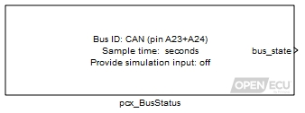 |
CAN bus status (pcx_BusStatus) Provide information about the error status of a CAN bus. |
Blocks are provided to help determine whether a CAN message is being received regularly, has yet to receive a CAN message, has not received a CAN message within a start-up period, has stopped receiving CAN messages, and converting values to and from engineering units to raw CAN data bytes.
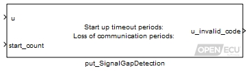 |
Signal gap detection (put_SignalGapDetection) Determine discontinuities in CAN message reception. |
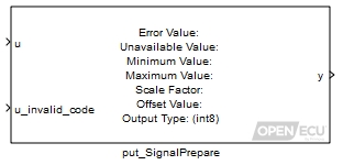 |
Signal prepare (put_SignalPrepare) Prepare signals for CAN transmission. |
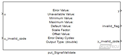 |
Signal validate (put_SignalValidate) Validate and scale received CAN signal values. |
The CAN Calibration Protocol (CCP) is a CAN based messaging system specified by ASAM and designed to work with calibration tools for application development purposes. At the end of a successful model build, OpenECU will generate an ASAP-2 file which describes the variables and calibratable data from the model. A compliant calibration tool reads the ASAP-2 file and communicates to the ECU using CAN messages to access or change the model data using the CCP protocol (ASAP-1b) in real-time.
Support for CCP communication in an application starts by configuring the CCP protocol, including CAN identifiers for CAN messages, station address and CAN bus. Each supported raster can be adjusted in size and rate to balance CAN bus loading for large CCP data measurements.
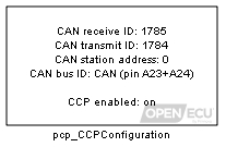 |
CCP configuration (pcp_CCPConfiguration) This block configures the way OpenECU handles any CAN Calibration Protocol (CCP) messages it receives. |
 |
CCP raster configuration (pcp_RasterConfig) This block configures CCP DAQ rasters. |
Once configured, OpenECU takes care of communicating with the calibration tool, allowing a user to change calibrations whilst the application runs on the target (if supported by the target ECU), acquire data from the application as it runs on the target at different acquisition rates, and reprogram the ECU with applications.
To prevent unauthorised access to these functions, an application can specify a security exchange that the calibration tool must adhere to. Only users with a matching security exchange can then change calibrations, acquire data or reprogram the ECU.
 |
CCP seed/key security (pcp_CCPSecurity) Control whether seed/key security is required for CCP calibration, data acquisition and/or reprogramming. |
When the ECU is reprogrammed, the ECU stops running the application and output drivers default to an off state. If there are situations where reprogramming an ECU would be detrimental to controlling a system (for example, accidentally starting a reprogramming session whilst fueling an engine) then the application can prevent reprogramming during these situations.
 |
CCP inhibit reprogramming (pcp_CCPInhibitReprogramming) Control whether reprogramming can occur via CCP when the application is running. |
There are some blocks providing auxiliary support:
 |
CCP CRO receive count (pcp_CCPRxCount) Get the number of CCP CRO messages received since the last reset. |
The ISO messaging protocol is a CAN based messaging system designed to pass information between vehicle network ECUs in real-time. OpenECU is designed to communicate with an external diagnostic scan or test tool using a subset of ISO 15765-2 based protocols, including SAE J1979 (ISO 15031-5, “OBD2”), KeyWord Protocol 2000-3 (KWP2000, ISO 14230-3), and Unified Diagnostic Services (UDS, ISO 14229-1).
An application starts by configuring the ECU's behaviour when handling ISO 15765 messages. This includes selecting which CAN bus to use for ISO messaging, specifying the transmit and receive message IDs, as well as other parameters that adjust the amount of memory set aside for processing ISO messages.
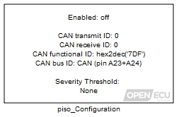 |
ISO configuration (piso_Configuration) Configure the ECU for ISO diagnostic communications. |
Most service requests are automatically handled by OpenECU requiring little intervention by the application. When the application must provide information then OpenECU provides blocks, including those involved in Diagnostic Trouble Codes, Freeze Frames, In-use Performance Ratios (covered later in this document) and vehicle information.
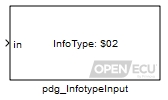 |
J1979 service $09 Infotype input (pdg_InfotypeInput) Declares vehicle specific information (VIN, calibration ID, etc) as per service $09 of the J1979 diagnostic protocol. |
Certain UDS/KWP2000 services can be restricted to protect the ECU from unauthorised changes or having the contents of the ECU read out over CAN.
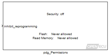 |
ISO security permissions (pdg_Permissions) Configure whether sensitive services are available and related SecurityAccess settings. |
Extended data records convey status information associated with a DTC in UDS service $19. The information is retrieved at the time of the request. The platform allows the assignment of DTC extended data record numbers within the manufacturer specific range, as well as the range reserved for legislated OBD DTC extended data records.
 |
ISO DTC extended data records (pdg_ExtendedDataRecord) UDS service $19 ExtendedDataRecord configuration. |
Routines can be used to allow a diagnostic tool to perform a custom function within the ECU using UDS service $31. For example, a function of the ECU can be started and stopped from the diagnostic tool, or a set of values can be written to or read from ECU memory. The actual routine is defined by the application software.
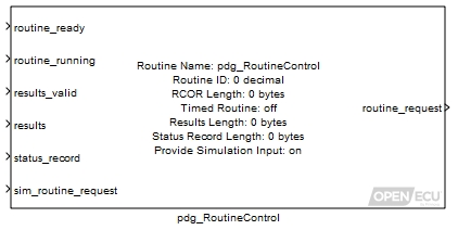 |
Routine control (pdg_RoutineControl) Communicates UDS service 0x31 (routine control) IO to and from a diagnostic scan tool. |
Like CCP communications, it is possible to reprogram the ECU using UDS messages. And like CCP communications, the application may prevent reprogramming where it is critical the application continues to run.
The J1939 messaging protocol is a CAN based messaging system designed to pass information between vehicle network ECUs in real-time. OpenECU is designed to communicate with an external diagnostic scan or test tool using a subset of SAE J1939 protocols, including part 21 for single and multi-packet messages, part 73 for diagnostics requirements, part 71 for vehicle application messages, and part 81 for network management.
An application starts by configuring the ECU's behavior when handling SAE J1939 messages. This includes selecting which CAN buses to use for J1939 messaging and specifying the network node names, source addresses, and other parameters that adjust the amount of memory set aside for processing J1939 messages.
 |
J1939 configuration (pj1939_Configuration) Configure the ECU for J1939 communications. |
 |
J1939 channel configuration (pj1939_ChannelConfiguration) Configure a J1939 communications channel. |
The blockset supports a subset of the J1939 specification from parts 21, 71, 73 and 81.
Handles requests for parameters by filtering out PGNs the model does not handle and returning NACK messages.
Handles reception and transmission of J1939 messages, in a similar way to other CAN receive and transmit blocks.
Handles the transport protocol (J1939/21) for sending long messages (up to 1785 bytes in length).
Handles some of the diagnostic requirements (J1939/73) for sending and receiving lists of diagnostic trouble codes (DM1 and DM2 messages). This includes support in the blockset for diagnostic trouble codes.
Handles the network protocol (J1939/81) as if the ECU and the rest of the network have fixed network nodes.
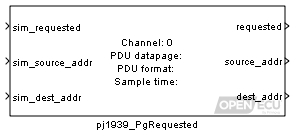 |
J1939 parameter group requested (pj1939_PgRequested) Determine whether a Parameter Group (PG) has been requested by another J1939 network node. |
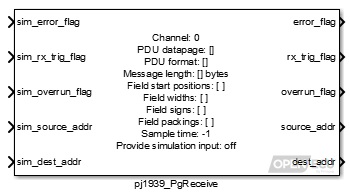 |
J1939 parameter group receive message (pj1939_PgReceive) Extract the data contents from a received J1939 message. |
|
|
J1939 parameter group transmit (pj1939_PgTransmit) Construct the contents of a J1939 message, and attempt to transmit it. |
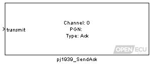 |
J1939 send acknowledgement message (pj1939_SendAck) Attempt to send an acknowledgement in response to a J1939 request. |
The blockset supports a large subset of the diagnostic messages defined in J1939-71, including diagnostic trouble code and lamp reporting, freeze frame reporting, diagnostic readiness information, commanded tests or last measured test results, performance ratio reporting, emission level exceedance reporting, NTE status and vehicle harmonised road-worthiness reporting.
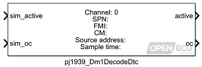 |
J1939 DM1 decode DTC (pj1939_Dm1DecodeDtc) Decodes the contents of the last received J1939-73 DM1 message based on specified DTC data. |
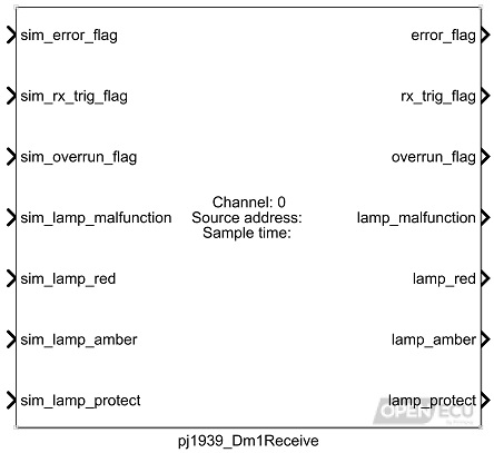 |
J1939 DM1 receive (pj1939_Dm1Receive) Indicates if a J1939/73 DM1 message has been received and decodes the contents of the lamp status. |
|
|
J1939 DM1 transmit (pj1939_Dm1Transmit) Transmit a J1939-73 DM1 message containing the DTCs with an active state from a DTC table. |
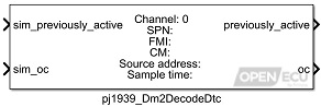 |
J1939 DM2 decode DTC (pj1939_Dm2DecodeDtc) Decodes the contents of the last received J1939-73 DM2 message based on specified DTC data. |
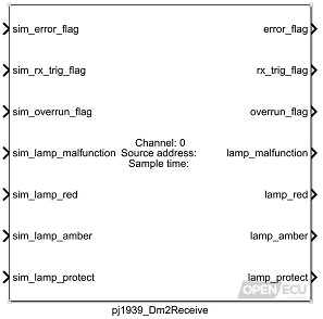 |
J1939 DM2 receive (pj1939_Dm2Receive) Indicates if a J1939-73 DM2 message has been received and decodes the contents of the lamp status. |
|
|
J1939 DM2 transmit (pj1939_Dm2Transmit) Transmit a J1939/73 DM2 message containing the DTCs with a previously active state from a DTC table. |
|
|
J1939 DM4 transmit (pj1939_Dm4Transmit) Transmit a J1939/73 DM4 message containing freeze frame data. |
|
|
J1939 DM5 transmit (pj1939_Dm5Transmit) Transmit a J1939/73 DM5 message containing the diagnostic readiness 1 data. |
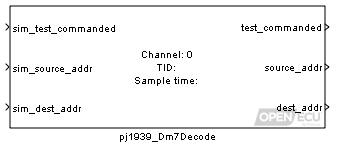 |
J1939 DM7 decode (pj1939_Dm7Decode) Decodes the contents of a received J1939/73 DM7 message. |
|
|
J1939 DM8 transmit (pj1939_Dm8Transmit) Transmit a J1939/73 DM8 message containing the test results for one of the non-continuously monitored tests invoked using DM7. Refer to J1939-73 FEB2010 section 5.7.8 for details. |
|
|
J1939 DM10 transmit (pj1939_Dm10Transmit) Transmit a J1939/73 DM10 message containing the list of non-continuously monitored systems tests supported by the controller. Refer to J1939-73 FEB2010 section 5.7.10 for details. |
|
|
J1939 DM20 transmit (pj1939_Dm20Transmit) Transmit a J1939/73 DM20 message containing the Performance Ratio Monitor data. |
|
|
J1939 DM21 transmit (pj1939_Dm21Transmit) Transmit a J1939/73 DM21 message containing the diagnostic readiness 2 data. |
|
|
J1939 DM24 transmit (pj1939_Dm24Transmit) Transmit a J1939/73 DM24 message identifying supported SPNs. |
|
|
J1939 DM25 transmit (pj1939_Dm25Transmit) Request that a J1939 DM25 (expanded freeze frame) message is transmitted. |
|
|
J1939 DM26 transmit (pj1939_Dm26Transmit) Transmit a J1939/73 DM26 message containing the diagnostic readiness 3 data. |
|
|
J1939 DM30 transmit (pj1939_Dm30Transmit) Transmit a J1939/73 DM30 message containing the scaled test results for the applicable test(s) requested in a DM7 message. Refer to J1939-73 Jul2013 section 5.7.30 for details. |
|
|
J1939 DM32 transmit (pj1939_Dm32Transmit) Transmit a J1939/73 DM32 message containing the regulated exhaust emission level exceedance data. Refer to J1939-73 Feb2010 section 5.7.32 for details. |
|
|
J1939 DM33 transmit (pj1939_Dm33Transmit) Transmit a J1939/73 DM33 message. Refer to J1939-73 Feb2010 for details. |
|
|
J1939 DM34 transmit (pj1939_Dm34Transmit) Transmit a J1939/73 DM34 message containing the NTE status data. Refer to J1939-73 Feb2010 section 5.7.34 for details. |
|
|
J1939 DM35 transmit (pj1939_Dm35Transmit) Transmit a J1939/73 DM35 message containing the transient fault status of DTCs, from a DTC table. |
|
|
J1939 DM36 transmit (pj1939_Dm36Transmit) Transmit a J1939/73 DM36 message containing the vehicle harmonised roadworthiness data. Refer to J1939-73 Feb2010 section 5.7.36 for details. |
|
|
J1939 DM37 transmit (pj1939_Dm37Transmit) Transmit a J1939/73 DM37 message containing the vehicle harmonised roadworthiness data. Refer to J1939-73 Feb2010 section 5.7.37 for details. |
|
|
J1939 DM38 transmit (pj1939_Dm38Transmit) Transmit a J1939/73 DM38 message containing the Harmonised Global Technical Regulation (GTR) description. Refer to J1939-73 Feb2010 section 5.7.38 for details. |
|
|
J1939 DM39 transmit (pj1939_Dm39Transmit) Transmit a J1939/73 DM39 message containing the system cumulative continuous MI data. Refer to J1939-73 Feb2010 section 5.7.39 for details. |
|
|
J1939 DM40 transmit (pj1939_Dm40Transmit) Transmit a J1939/73 DM40 message containing the harmonised B1 failure counts. Refer to J1939-73 Feb2010 section 5.7.40 for details. |
|
|
J1939 Transmit DTC DM (pj1939_TransmitDtcDm) Transmit a J1939/73 DM message to a specific destination address. Supports DM6, DM12, DM23, DM27, DM28, DM29, DM31, DM41, DM42, DM43, DM44, DM45, DM46, DM47, DM48, DM49, DM50, DM51, and DM52. |
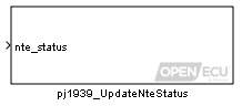 |
J1939 update NTE status (pj1939_UpdateNteStatus) Provide the facility to update the NTE status (as reported in J1939 message DM34). |
The platform uses the SPI protocol to communicate between the main microprocessor and various other peripheral devices on the ECU. This is all handled internally by the OpeECU platform; however, it does provide an interface to report faulty communications with such devices to the application.
 |
SPI communication fault count (psp_FaultCount) Interface to read the number of SPI transmit errors on a given device since initialisation. |
OpenECU provides blocks to support Diagnostic Trouble Codes (DTCs). DTCs are the basic building blocks of OpenECU's diagnostic support. There are multiple standards for the fault information to follow as well as choices for its life-cycle depending on whether it is emissions-related or permanent and the legislation being followed. These details are selected within the Simulink definition block for each DTC and allow the user to configure the system for various aspects of diagnostic legislation.
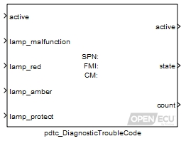 |
DTC diagnostic trouble code (pdtc_DiagnosticTroubleCode) Set the state and auxiliary data about a diagnostic trouble code. |
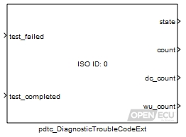 |
DTC diagnostic trouble code (extended) (pdtc_DiagnosticTroubleCodeExt) Define a diagnostic trouble code, and provide the platform with information relating to its fault conditions. |
DTCs may be grouped into named tables to help the user manipulate them. DTCs can be individually updated or cleared. DTCs can be cleared by group, based on a match to DTC type, emission severity and state, or cleared by table.
 |
DTC table definition (pdtc_Table) Declares a table of diagnostic trouble codes (DTCs), that can be referred to by other blocks that wish to refer to a group of DTCs. |
|
|
DTC clear all (pdtc_ClearAll) Set all DTCs referred to by the table identifier parameter, to the clear state, if the clear state is supported by the DTC. |
|
|
DTC clear all if active (pdtc_ClearAllIfActive) Set all DTCs referred to by the table identifier parameter, to the clear state, if the clear state is supported by the DTC, and if the DTC state is currently active. |
|
|
DTC clear all if inactive (pdtc_ClearAllIfInactive) Set all DTCs referred to by the table identifier parameter, to the clear state, if the clear state is supported by the DTC, and if the DTC state is currently "inactive" or "previously active". |
|
|
DTC match and clear (pdtc_ClearDtcs) Clear all DTCs which match the DTC type, DTC emissions severity and DTC state, in accordance with the comparator parameters. |
|
|
DTC table cleared indication (pdtc_TableCleared) The pdtc_TableCleared block can be used to signal when a diagnostic command to clear all DTCs (or a subset of DTCs) has been received for the specified table. |
The application can determine the existence of DTCs which match the DTC type, DTC emissions severity and DTC state.
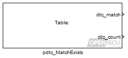 |
DTC match exists (pdtc_MatchExists) Determine the existence of DTCs which match the DTC type, DTC emissions severity and DTC state. |
Control of DTCs can depend on the number of drive, warm-up and ignition cycles that have taken place as well as the engine running state. A block is provided to signal the start of each cycle and the engine running state. The application determines the conditions for starting each of the cycles and the engine running state, as these can be dependent on the regulatory requirements that are being adhered to.
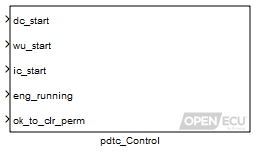 |
DTC control (pdtc_Control) Start new drive, warm-up and ignition cycles. Handle engine running signal. Handle vehicle/operating conditions for OBD clear of CARB permanent DTCs. |
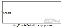 |
DTC enable periodic lamp updates (pdtc_EnablePeriodicLampUpdates) Allows an application to enable or disable periodic processing of the pdtc lamp status. |
Various regulatory requirements specify the need to light different lamps based on DTC status. A block is provided to indicates the required states of the Malfunction Indicator Lamp, the Red Stop Lamp, the Amber Warning Lamp and the Protection Lamp based on all DTCs defined by the application.
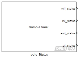 |
DTC lamp states (pdtc_Status) Firstly, this indicates the required states of the Malfunction Indicator Lamp, the Red Stop Lamp, the Amber Warning Lamp and the Protection Lamp. These states are determined having taken into consideration the states of all DTCs in the system. Optionally, values are output required to support EuroVI MIL activation and to populate messages with MIL and B1-severity fault time counter values. |
The application can store DTCs in non-volatile memory across power cycles.
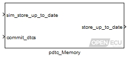 |
DTC memory update (pdtc_Memory) Retain the DTC tables in non-volatile storage across power cycles. |
OpenECU provides Simulink blocks to support Parameter Identifiers (PID). A PID is used to access the current value of an application parameter by a diagnostic scan tool. The access includes reading the parameter and if enabled over-riding the parameter. If the parameter is a non-volatile PID, this value can be written to non-volatile memory and retained across power cycles.
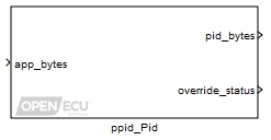 |
Parameter identifier (ppid_Pid) Captures the current value of a parameter to internal memory or non-volatile memory for access by a diagnostic scan tool. |
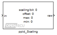 |
Parameter identifier scaling (ppid_Scaling) This block outputs a raw byte value to represent the input with the scaling applied. |
OpenECU provides Simulink blocks to support freeze frames. DTCs can have an associated freeze frame that is stored when the fault occurs. The application may specify several different types of freeze frame for use with different DTCs. The various freeze frame definitions may include more or less data to be captured when a fault occurs.
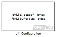 |
Freeze frame configuration (pff_Configuration) Specifies the amount of volatile (RAM) and non-volatile (flash) memory allocated for freeze frame storage. |
 |
Freeze frame (pff_FreezeFrame) Captures a list of specified parameters upon the occurrence of an active DTC. The captured parameter values are stored for access by a diagnostic scan tool. |
 |
DM25 freeze frame (pff_Dm25FreezeFrame) Specifies the list of SPN(s) to capture for a DM25 freeze frame. |
For a specific piece of data to be captured in a freeze-frame, the application must provide the data to the freeze frame block via inports. The block will capture the latest data from the inport to the PID block when required. The same PID block mechanism OpenECU to provide real-time data from the application to a diagnostic scan tool (e.g. for J1979 service $01 or J1939 DM24).
OpenECU provides Simulink blocks to support diagnostic monitors, tests and performance ratios. A complete emissions related diagnostic system will have a have a set of diagnostic monitors to check the performance of each of the various components on a vehicle. These diagnostic monitors are in turn made of a series of diagnostic tests. The individual tests may be performed continuously, for example checking the range of an analogue input or the state of an output signal. Alternatively the tests may be classed as non-continuous which means that they can only be performed when the vehicle is in a certain operating state, for example checking the performance of a catalyst or the EGR sub-system.
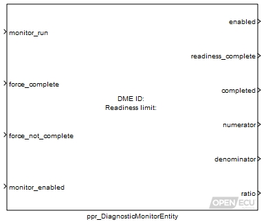 |
Diagnostic monitor entity (ppr_DiagnosticMonitorEntity) Define a Diagnostic Monitor Entity. |
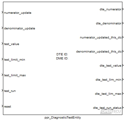 |
Diagnostic test entity (ppr_DiagnosticTestEntity) Define a Diagnostic Test Entity and the inputs which operate on it. |
 |
General denominator (ppr_GeneralDenominator) Provide the means to update the In-use performance ratio general denominator. |
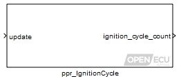 |
Ignition cycle (ppr_IgnitionCycle) Provide the means to update the In-use performance ratio ignition cycle counter. |
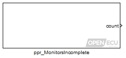 |
Monitors incomplete count (ppr_MonitorsIncomplete) Provide a count of the total number of monitors (DMEs) that are enabled and have a readiness status of not complete. |
The application uses these blocks in conjunction with their individual diagnosis algorithms and provide data from each time an individual test is performed. The data is used in two ways by OpenECU:
Firstly, each time a test is run, this allows the platform to update the numerator and denominator to be used in calculating the In Use Performance Ratio for that particular diagnostic.
Secondly the most recent test results and limits must be available for communication to a diagnostic scan tool. The application can store this data in non-volatile memory across power cycles for future communication to a scan tool.
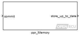 |
PPR memory update (ppr_Memory) Retain the In-use performance ratio data in non-volatile storage across power cycles. |
OpenECU provides Simulink blocks that allow the application to adjust scalars, 1-d and 2-d maps while the application runs on the target ECU. An example might be learning the range of a component as mechanical wear changes the dimensions of the component, such as a throttle body.
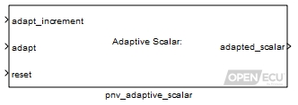 |
Non-volatile adaptive scalar (pnv_AdaptiveScalar) Non-volatile adaptive scalar block. |
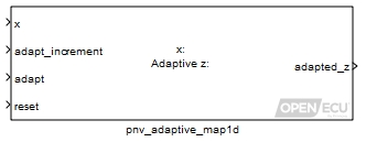 |
Non-volatile adaptive 1-d map look-up (pnv_AdaptiveMap1d) Adaptive 1-d map look-up and interpolation. |
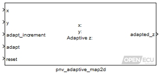 |
Non-volatile adaptive 2-d map look-up (pnv_AdaptiveMap2d) Adaptive 2-d map look-up and interpolation. |
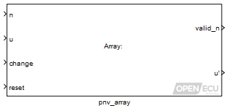 |
Non-volatile adaptive array (pnv_Array) Adaptive array non-volatile storage. |
The adaptive data defined by these blocks can be stored in non-volatile memory across power cycles.
OpenECU provides a set of blocks for utility purposes, covering map look-up and interpolation, simple signal conditioning and ECU reset information.
OpenECU provides blocks for efficient map look-up and interpolation.
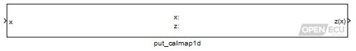 |
1-d calibration map look-up and interpolation (put_Calmap1d) 1-d map look-up and interpolation. |
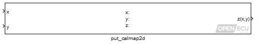 |
2-d calibration map look-up and interpolation (put_Calmap2d) 2-d map look-up and interpolation. |
OpenECU provides blocks for simple signal conditioning, such as digital signal debouncing, or rate of change checking and substitution.
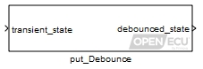 |
Debounce (put_Debounce) Output a new value of the debounced state only if the transient state has remained constant for a number of cycles. |
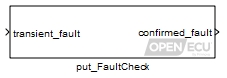 |
Fault check (put_FaultCheck) Debounce a transient fault signal into a confirmed fault signal using a leaky bucket algorithm. |
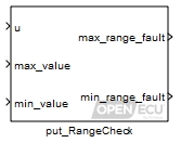 |
Range check (put_RangeCheck) Range check the input and provide fault information from the range check. |
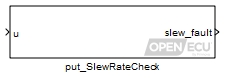 |
Slew rate check (put_SlewRateCheck) Set the outport if the rate of change of inport is too great. |
For configuration management purposes, it can be useful to restrict the version of OpenECU software that can be used when editing and building an application model. The OpenECU blockset provides a flexible way to specify the allowable versions.
 |
Require platform version (put_RequirePlatformVersion) Stop a model build if the wrong version of the OpenECU platform is selected. |
For configuration management and debugging purposes, it can be useful to know the versions of software running on an ECU are compatible. The blockset library provides a way to retrieve the version numbers of the various software components running on an ECU.
 |
Boot code version (psc_BootVersion) Get the version information for the ECU's boot code. |
 |
Platform code version (psc_PlatformVersion) Get the version information for the ECU's platform code. |
 |
Reprogramming code version (psc_PrgVersion) Get the version information for the ECU's reprogramming code. |
The application can retrieve the date that each of those software components was built.
 |
Boot code build date (psc_BootBuildDate) Get the build date for the ECU's boot code. |
 |
Platform code build date (psc_PlatformBuildDate) Get the build date for the ECU's platform code. |
 |
Reprogramming code build date (psc_PrgBuildDate) Get the build date for the ECU's reprogramming code. |
The application can retrieve the part number used to identify each of those software components.
 |
Boot code part number (psc_BootPartNumber) Get the part number information for the ECU's boot code. |
 |
Platform code part number (psc_PlatformPartNumber) Get the part number information for the ECU's platform code. |
 |
Reprogramming code part number (psc_PrgPartNumber) Get the part number information for the ECU's reprogramming code. |
The application can retrieve version and build date information about itself.
 |
Application version (psc_AppVersion) Get the version information for the ECU's application. |
 |
Application build date (psc_AppBuildDate) Get the build date for the ECU's application. |
The application can determine if the application code or calibration memory regions have been altered for self-verification and diagnostic scan tool purposes.
 |
Calibration verification number (CVN) (psc_CvnCalc) Calculates the calibration verification number of the code and calibration memory regions. |
OpenECU provides a fixed-priority, pre-emptive, Real-Time Operating System to schedule application tasks and OpenECU tasks. When Simulink Coder generates code for the application model, it gathers functionality that runs at the same rate into tasks. The priority of each application task is assigned according to model rate.
The application can retrieve information about task timing and overall CPU/eTPU loading whilst the application is running.
 |
Task duration (pkn_TaskDuration) Get the last measured or maximum duration for a given model rate (task). |
 |
Task period overrun (pkn_TaskPeriodOverrun) Get the count of overruns for a given model rate (periodic task). |
 |
Processor loading (psc_CpuLoading) Get the average processor loading for the running application. |
 |
eTPU loading (psc_EtpuLoading) Get the average eTPU loading for the running application. |
Each task shares the same stack space, an area of RAM dedicated to storing temporary information about the task and the functionality the task is performing. The amount of stack space is finite and is specified in the model's settings. The application can retrieve information about stack use since ECU power on or last reset.
 |
Stack used (psc_StackUsed) Get the maximum number of bytes used by the stack since power on (or reset). |
Each ECU implements a watchdog, a hardware mechanism to reset the ECU if the ECU software appears to be misbehaving. A simple watchdog scheme is implemented by the platform software but the application model can take control of the watchdog and implement a more complex scheme.
 |
Watchdog kick (psc_KickWatchdog) Kick the processor watchdog to avoid reset. |
The application can retrieve information about the last ECU reset, including the cause of the reset and the duration taken to boot the application.
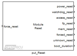 |
Reset module (put_Reset) Provide reset information and a mechanism to reset the ECU. |
The application can retrieve the number of stable and unstable powered resets.
 |
Reset count — stable (psc_ResetCount) Get the free running count of the number of powered resets. |
 |
Reset count — unstable (psc_UnstableResetCount) Get the count of the number of unstable powered resets. |
Non-volatile memory devices, like Flash, hold the ECU's firmware and application software, whilst volatile memory devices, like RAM, hold the ECUs working data. Failures in memory devices can result in undefined behaviour from the software. Memories are continuously checked for errors. Recoverable errors are handled and reported to the application. Unrecoverable errors cause the ECU to reset.
The application can retrieve information about memory test progress whilst the application is running.
 |
Internal RAM test progress (psc_InternalRamTestProgress) Get the progress information for the ECU's free running internal RAM test. |
 |
Internal ROM test progress (psc_InternalRomTestProgress) Get the progress information for the ECU's free running internal ROM test. |
The application can retrieve information about recoverable memory errors that have been detected whilst the application is running.
 |
Internal RAM test error (psc_InternalRamTestError) Get the recoverable error information for the ECU's free running internal RAM test. |
 |
Internal ROM test error (psc_InternalRomTestError) Get the recoverable error information for the ECU's free running internal ROM test. |
Real time applications, like those developed for OpenECU, often need to time events or durations, at different resolutions. The blockset library provides two mechanisms to manipulate time: using the Simulink task timers which have a course time resolution matching the fastest model rate; and using the ECU processor's timers which have a much finer resolution.
 |
Time (Simulink) (ptm_SimulinkTime) Output the time since the model started (absolute), or output the time since the last time the block executed (relative). |
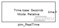 |
Time (real) (ptm_RealTime) Output the time since the model started (absolute), or output the time since the last time the block executed (relative). |
 |
Show Simulink's sample time colours (prtw_ShowSampleTimeColours) Turn on Simulink's sample time colours. |
To support switching between auto-coders, the blockset library provides a set of blocks which switch between the different configuration sets. Simulink configuration sets contain options for a specific auto-coder. Currently, building models against the RTW (GRT RTMODEL) and RTW (EC) auto-coders is supported.
 |
Configure auto-coder (RTW RTMODEL) (prtw_ConfigUsingRtwRtmodel) Configure Simulink to use the Simulink Coder RTMODEL auto-coder. |
 |
Configure auto-coder (RTW EC) (prtw_ConfigUsingRtwEc) Configure Simulink to use the Embedded Coder auto-coder. |
The blockset provides a utility block to start a model build. Pressing CTRL+B in a model window performs the same functionality.
 |
Build model (prtw_Build) Start a model build. |
OpenECU provides support for several different compilers to suit the application needs. Support includes some versions of the Wind River Diab and GNU GCC compilers.
Although not necessary in the majority of cases, it is sometimes useful to be able to modify the compiler or linker options while building a model. For instance, to turn on debug symbols, to turn off an optimisation which may be causing a problem, or to affect preprocessor conditions of hand written code included in the build.
 |
Compiler options (pcomp_CompileOptions) Specify or append compiler options when building a model. |
 |
Link options (pcomp_LinkOptions) Specify or append linker options when building a model. |
| Interfaces |
M110 000 |
M220 000 |
M220 0AU |
M221 000 |
M250 000 |
M460 000 |
M461 000 |
M670 000 |
|---|---|---|---|---|---|---|---|---|
| Target ECU identification and configuration | ||||||||
| Model identification (put_Identification) | Y | Y | Y | Y | Y | Y | Y | Y |
| Configuration M250 (pcfg_Config_M250) | - | - | - | - | Y | - | - | - |
| Configuration M460 (pcfg_Config_M460) | - | - | - | - | - | Y | - | - |
| Configuration M670 (pcfg_Config_M670) | - | - | - | - | - | - | - | Y |
| Retrieve registry key (preg_RetrieveKey) | Y | Y | Y | Y | Y | Y | Y | Y |
| Input/output signal processing — time based | ||||||||
| Analogue input — processed (pai_AnalogInput) | Y | Y | Y | Y | Y | Y | Y | Y |
| Analogue input — basic (pai_BasicAnalogInput) | Y | Y | Y | Y | Y | Y | Y | Y |
| Digital input (pdx_DigitalInput) | Y | Y | Y | Y | Y | Y | Y | Y |
| Frequency input (pdx_FrequencyInput) | Y | Y | Y | Y | Y | Y | Y | Y |
| PWM input measurement (pdx_PwmInput) | Y | Y | Y | Y | Y | Y | Y | Y |
| Quadrature decode input (pdx_QuadratureDecode) | Y | - | Y | - | Y | Y | Y | Y |
| Quadrature decode and frequency input measurement (pdx_QuadratureDecodeAndFrequencyInput) | Y | - | Y | - | Y | Y | Y | Y |
| SENT input (pdx_SentInput) | Y | - | - | - | - | - | - | Y |
| SENT input — serial data (pdx_SentSerialInput) | Y | - | - | - | - | - | - | Y |
| Digital data input (pdd_DataInput) | Y | Y | Y | Y | Y | Y | Y | Y |
| Digital output monitor (pdx_Monitor) | Y | - | - | - | - | - | - | Y |
| Constant current output (pax_CcOutput) | - | - | - | - | - | - | - | Y |
| Digital output (pdx_DigitalOutput) | Y | Y | Y | Y | Y | Y | Y | Y |
| PWM output — fixed frequency (pdx_PWMOutput) | Y | Y | Y | Y | Y | Y | Y | Y |
| PWM output — variable frequency, synchronised (pdx_PWMSynchronisedOutput) | Y | - | - | - | Y | Y | - | Y |
| PWM output — variable frequency (pdx_PWMVariableFrequencyOutput) | Y | Y | Y | Y | Y | Y | Y | Y |
| Peak and hold injector output (pdx_PeakHoldInjectorOutput) | - | - | - | - | - | - | - | - |
| H-Bridge output (pdx_HBridgeOutput) | - | Y | Y | - | Y | - | - | Y |
| Constant current output — configuration for TLE8242-2 outputs (pax_CcConfigTle8242) | - | - | - | - | - | - | - | Y |
| Constant current output — autozero for TLE8242-2 channels (pax_CcAutozeroTle8242) | - | - | - | - | - | - | - | Y |
| Constant current output — monitor for TLE8242-2 channels (pax_CcReadCurrentTle8242) | - | - | - | - | - | - | - | Y |
| UEGO sensor control — CJ125 device (pcj125_Control) | - | - | - | - | - | - | - | Y |
| Output control (pss_OutputControl) | - | - | - | - | Y | Y | - | - |
| Over-current trip reset (pss_OvercurTripReset) | - | Y | Y | Y | Y | - | Y | Y |
| Over current trip reset and diagnostic enable (pss_OvercurTripReset_DiagnEnable) | - | - | - | - | - | Y | - | - |
| Input/output signal processing — engine/angular based | ||||||||
| Engine configuration (pan_EngineConfig) | - | Y | - | Y | Y | - | - | Y |
| Crank wheel — configuration (pan_CrankWheelConfig) | - | Y | - | Y | Y | - | - | Y |
| Crank wheel — extended configuration (pan_CrankWheelConfigExt) | - | Y | - | Y | Y | - | - | Y |
| Cam wheel — configuration (pan_CamWheelConfig) | - | Y | - | Y | Y | - | - | Y |
| Crank wheel — movement (pan_CrankWheelMovement) | - | Y | - | Y | Y | - | - | Y |
| Crank wheel — synchronisation (pan_CrankWheelSync) | - | Y | - | Y | Y | - | - | Y |
| Crank wheel — tooth (pan_CurrentCrankTooth) | - | Y | - | Y | Y | - | - | Y |
| Crank wheel — angle (pan_CurrentCrankAngle) | - | Y | - | Y | Y | - | - | Y |
| Crank wheel — speed (pan_CrankWheelSpeed) | - | Y | - | Y | Y | - | - | Y |
| Crank wheel — secondary phase angle (pan_CrankSecondaryPhase) | - | - | - | - | - | - | - | Y |
| Crank wheel — sync point last (pan_CrankWheelSyncPointLast) | - | Y | - | Y | Y | - | - | Y |
| Crank wheel — sync point next (pan_CrankWheelSyncPointNext) | - | Y | - | Y | Y | - | - | Y |
| Crank wheel — sync point trigger (pan_CrankWheelSyncPointTrigger) | - | Y | - | Y | Y | - | - | Y |
| Crank wheel — digital input (pan_CrankWheelDigitalInput) | - | Y | - | - | Y | - | - | Y |
| Crank wheel — decoding (pan_CrankWheelDecodeState) | - | Y | - | Y | Y | - | - | Y |
| Cam wheel — digital input (pan_CamWheelDigitalInput) | - | Y | - | Y | Y | - | - | Y |
| Cam wheel — movement (pan_CamWheelMovement) | - | Y | - | Y | Y | - | - | Y |
| Cam wheel — tooth edge angles (pan_CamWheelToothEdgeAngles) | - | Y | - | Y | Y | - | - | Y |
| Engine synchronisation — declare mode (pan_EngineDeclareSync) | - | Y | - | Y | Y | - | - | Y |
| Engine synchronisation — declare loss of synchronisation (pan_EngineLoseSync) | - | Y | - | Y | Y | - | - | Y |
| Engine synchronisation (pan_EngineSync) | - | Y | - | Y | Y | - | - | Y |
| Engine speed (pan_EngineSpeed) | - | Y | - | Y | Y | - | - | Y |
| Engine tooth (pan_CurrentEngineTooth) | - | Y | - | Y | Y | - | - | Y |
| Engine angle (pan_CurrentEngineAngle) | - | Y | - | Y | Y | - | - | Y |
| Engine cylinder (pan_CurrentCylinder) | - | Y | - | Y | Y | - | - | Y |
| Analogue input — angular, configuration (pan_AngularAnalogInput_Config) | - | Y | - | Y | Y | - | - | Y |
| Analogue input — angular, variable relative angle (pan_AngularAnalogInputVariable) | - | Y | - | Y | Y | - | - | Y |
| Analogue input — angular, variable absolute angle (pan_AngularAnalogInputVariableAbs) | - | Y | - | Y | Y | - | - | Y |
| Knock configuration (pan_KnockConfig) | - | - | - | - | - | - | - | Y |
| Knock detection window (pan_KnockDetectionWindow) | - | - | - | - | - | - | - | Y |
| Knock filter — HIP901x (pan_KnockFilter_Hip901x) | - | - | - | - | - | - | - | Y |
| Knock feedback (pan_KnockFeedback) | - | - | - | - | - | - | - | Y |
| Injection configuration — multiple outputs (pan_InjectorConfig) | - | Y | - | Y | Y | - | - | Y |
| Injection configuration — single output (pan_SingleInjectorConfig) | - | Y | - | Y | Y | - | - | Y |
| Injection configuration — direct injection (pan_InjectorConfig_DI) | - | Y | - | Y | Y | - | - | Y |
| Injection configuration — fuel rail pressure compensation (pan_InjectorCompConfig_DI) | - | Y | - | Y | Y | - | - | Y |
| Injection direct — fuel rail pressure override (pan_InjectionOverrideFrp_DI) | - | Y | - | Y | Y | - | - | Y |
| Injection direct — set schedule (pan_Injection_DI) | - | Y | - | Y | Y | - | - | Y |
| Injection direct — setpoint feedback (pan_InjectionSetpoint_DI) | - | Y | - | Y | Y | - | - | Y |
| Injection direct — event feedback (pan_InjectionFeedback_DI) | - | Y | - | Y | Y | - | - | Y |
| Injection configuration — multiple outputs (pan_InjectorConfig) | - | Y | - | Y | Y | - | - | Y |
| Injection configuration — single output (pan_SingleInjectorConfig) | - | Y | - | Y | Y | - | - | Y |
| Injection port — initial fuel pulse (pan_InitialInjection_PI) | - | Y | - | Y | - | - | - | Y |
| Injection port — set schedule (pan_Injection_PI) | - | Y | - | Y | - | - | - | Y |
| Injection port — update injection schedule (pan_UpdateInjection_PI) | - | Y | - | Y | - | - | - | Y |
| Injection port — setpoint feedback (pan_InjectionSetpoint_PI) | - | Y | - | Y | - | - | - | Y |
| Injection port — event feedback (pan_InjectionFeedback_PI) | - | Y | - | Y | - | - | - | Y |
| Spark configuration (pan_SparkConfig) | - | Y | - | Y | Y | - | - | Y |
| Spark (pan_Spark) | - | Y | - | Y | Y | - | - | Y |
| Spark feedback (pan_SparkFeedback) | - | Y | - | Y | Y | - | - | Y |
| Digital output — angular configuration (pan_AngularOutputConfig) | - | - | - | - | - | - | - | Y |
| Digital output — angular digital (pan_AngularOutput) | - | - | - | - | - | - | - | Y |
| Communications — CAN | ||||||||
| CAN configuration (pcx_CANConfiguration) | Y | Y | Y | Y | Y | Y | Y | Y |
| CAN receive message (pcx_CANReceiveMessage) | Y | Y | Y | Y | Y | Y | Y | Y |
| CAN transmit message (pcx_CANTransmitMessage) | Y | Y | Y | Y | Y | Y | Y | Y |
| CANdb message receive (pcx_CANdb_ReceiveMessage) | Y | Y | Y | Y | Y | Y | Y | Y |
| CANdb transmit message (pcx_CANdb_TransmitMessage) | Y | Y | Y | Y | Y | Y | Y | Y |
| CAN bus status (pcx_BusStatus) | Y | Y | Y | Y | Y | Y | Y | Y |
| Signal gap detection (put_SignalGapDetection) | Y | Y | Y | Y | Y | Y | Y | Y |
| Signal prepare (put_SignalPrepare) | Y | Y | Y | Y | Y | Y | Y | Y |
| Signal validate (put_SignalValidate) | Y | Y | Y | Y | Y | Y | Y | Y |
| Communications — CCP | ||||||||
| CCP configuration (pcp_CCPConfiguration) | Y | Y | Y | Y | Y | Y | Y | Y |
| CCP raster configuration (pcp_RasterConfig) | Y | Y | Y | Y | Y | Y | Y | Y |
| CCP seed/key security (pcp_CCPSecurity) | Y | Y | Y | Y | Y | Y | Y | Y |
| CCP inhibit reprogramming (pcp_CCPInhibitReprogramming) | Y | Y | Y | Y | Y | Y | Y | Y |
| CCP CRO receive count (pcp_CCPRxCount) | Y | Y | Y | Y | Y | Y | Y | Y |
| Communications — ISO 15765 (J1979, KWP-2000, UDS) | ||||||||
| ISO configuration (piso_Configuration) | Y | Y | Y | Y | Y | Y | Y | Y |
| ISO security permissions (pdg_Permissions) | Y | Y | Y | Y | Y | Y | Y | Y |
| ISO DTC extended data records (pdg_ExtendedDataRecord) | Y | Y | Y | Y | Y | Y | Y | Y |
| Routine control (pdg_RoutineControl) | Y | Y | Y | Y | Y | Y | Y | Y |
| Communications — SAE J1939 | ||||||||
| J1939 configuration (pj1939_Configuration) | Y | Y | Y | Y | Y | Y | Y | Y |
| J1939 channel configuration (pj1939_ChannelConfiguration) | Y | Y | Y | Y | Y | Y | Y | Y |
| J1939 parameter group requested (pj1939_PgRequested) | Y | Y | Y | Y | Y | Y | Y | Y |
| J1939 parameter group receive message (pj1939_PgReceive) | Y | Y | Y | Y | Y | Y | Y | Y |
| J1939 parameter group transmit (pj1939_PgTransmit) | Y | Y | Y | Y | Y | Y | Y | Y |
| J1939 send acknowledgement message (pj1939_SendAck) | Y | Y | Y | Y | Y | Y | Y | Y |
| J1939 DM1 decode DTC (pj1939_Dm1DecodeDtc) | Y | Y | Y | Y | Y | Y | Y | Y |
| J1939 DM1 receive (pj1939_Dm1Receive) | Y | Y | Y | Y | Y | Y | Y | Y |
| J1939 DM1 transmit (pj1939_Dm1Transmit) | Y | Y | Y | Y | Y | Y | Y | Y |
| J1939 DM2 decode DTC (pj1939_Dm2DecodeDtc) | Y | Y | Y | Y | Y | Y | Y | Y |
| J1939 DM2 receive (pj1939_Dm2Receive) | Y | Y | Y | Y | Y | Y | Y | Y |
| J1939 DM2 transmit (pj1939_Dm2Transmit) | Y | Y | Y | Y | Y | Y | Y | Y |
| J1939 DM4 transmit (pj1939_Dm4Transmit) | Y | Y | Y | Y | Y | Y | Y | Y |
| J1939 DM5 transmit (pj1939_Dm5Transmit) | Y | Y | Y | Y | Y | Y | Y | Y |
| J1939 DM7 decode (pj1939_Dm7Decode) | Y | Y | Y | Y | Y | Y | Y | Y |
| J1939 DM8 transmit (pj1939_Dm8Transmit) | Y | Y | Y | Y | Y | Y | Y | Y |
| J1939 DM10 transmit (pj1939_Dm10Transmit) | Y | Y | Y | Y | Y | Y | Y | Y |
| J1939 DM20 transmit (pj1939_Dm20Transmit) | Y | Y | Y | Y | Y | Y | Y | Y |
| J1939 DM21 transmit (pj1939_Dm21Transmit) | Y | Y | Y | Y | Y | Y | Y | Y |
| J1939 DM24 transmit (pj1939_Dm24Transmit) | Y | Y | Y | Y | Y | Y | Y | Y |
| J1939 DM25 transmit (pj1939_Dm25Transmit) | Y | Y | Y | Y | Y | Y | Y | Y |
| J1939 DM26 transmit (pj1939_Dm26Transmit) | Y | Y | Y | Y | Y | Y | Y | Y |
| J1939 DM30 transmit (pj1939_Dm30Transmit) | Y | Y | Y | Y | Y | Y | Y | Y |
| J1939 DM32 transmit (pj1939_Dm32Transmit) | Y | Y | Y | Y | Y | Y | Y | Y |
| J1939 DM33 transmit (pj1939_Dm33Transmit) | Y | Y | Y | Y | Y | Y | Y | Y |
| J1939 DM34 transmit (pj1939_Dm34Transmit) | Y | Y | Y | Y | Y | Y | Y | Y |
| J1939 DM35 transmit (pj1939_Dm35Transmit) | Y | Y | Y | Y | Y | Y | Y | Y |
| J1939 DM36 transmit (pj1939_Dm36Transmit) | Y | Y | Y | Y | Y | Y | Y | Y |
| J1939 DM37 transmit (pj1939_Dm37Transmit) | Y | Y | Y | Y | Y | Y | Y | Y |
| J1939 DM38 transmit (pj1939_Dm38Transmit) | Y | Y | Y | Y | Y | Y | Y | Y |
| J1939 DM39 transmit (pj1939_Dm39Transmit) | Y | Y | Y | Y | Y | Y | Y | Y |
| J1939 DM40 transmit (pj1939_Dm40Transmit) | Y | Y | Y | Y | Y | Y | Y | Y |
| J1939 Transmit DTC DM (pj1939_TransmitDtcDm) | Y | Y | Y | Y | Y | Y | Y | Y |
| J1939 update NTE status (pj1939_UpdateNteStatus) | Y | Y | Y | Y | Y | Y | Y | Y |
| Communications — SPI | ||||||||
| SPI communication fault count (psp_FaultCount) | - | - | - | - | - | - | - | Y |
| OBD Infrastructure — Fault support | ||||||||
| DTC diagnostic trouble code (pdtc_DiagnosticTroubleCode) | Y | Y | Y | Y | Y | Y | Y | Y |
| DTC diagnostic trouble code (extended) (pdtc_DiagnosticTroubleCodeExt) | Y | Y | Y | Y | Y | Y | Y | Y |
| DTC table definition (pdtc_Table) | Y | Y | Y | Y | Y | Y | Y | Y |
| DTC clear all (pdtc_ClearAll) | Y | Y | Y | Y | Y | Y | Y | Y |
| DTC clear all if active (pdtc_ClearAllIfActive) | Y | Y | Y | Y | Y | Y | Y | Y |
| DTC clear all if inactive (pdtc_ClearAllIfInactive) | Y | Y | Y | Y | Y | Y | Y | Y |
| DTC match and clear (pdtc_ClearDtcs) | Y | Y | Y | Y | Y | Y | Y | Y |
| DTC table cleared indication (pdtc_TableCleared) | Y | Y | Y | Y | Y | Y | Y | Y |
| DTC match exists (pdtc_MatchExists) | Y | Y | Y | Y | Y | Y | Y | Y |
| DTC control (pdtc_Control) | Y | Y | Y | Y | Y | Y | Y | Y |
| DTC enable periodic lamp updates (pdtc_EnablePeriodicLampUpdates) | Y | Y | Y | Y | Y | Y | Y | Y |
| DTC lamp states (pdtc_Status) | Y | Y | Y | Y | Y | Y | Y | Y |
| DTC memory update (pdtc_Memory) | Y | Y | Y | Y | Y | Y | Y | Y |
| OBD Infrastructure — PID support | ||||||||
| Parameter identifier (ppid_Pid) | Y | Y | Y | Y | Y | Y | Y | Y |
| Parameter identifier scaling (ppid_Scaling) | Y | Y | Y | Y | Y | Y | Y | Y |
| OBD Infrastructure — Freeze Frame support | ||||||||
| Freeze frame configuration (pff_Configuration) | Y | Y | Y | Y | Y | Y | Y | Y |
| Freeze frame (pff_FreezeFrame) | Y | Y | Y | Y | Y | Y | Y | Y |
| DM25 freeze frame (pff_Dm25FreezeFrame) | Y | Y | Y | Y | Y | Y | Y | Y |
| OBD Infrastructure — In-Use Performance Ratio support | ||||||||
| Diagnostic monitor entity (ppr_DiagnosticMonitorEntity) | Y | Y | Y | Y | Y | Y | Y | Y |
| Diagnostic test entity (ppr_DiagnosticTestEntity) | Y | Y | Y | Y | Y | Y | Y | Y |
| General denominator (ppr_GeneralDenominator) | Y | Y | Y | Y | Y | Y | Y | Y |
| Ignition cycle (ppr_IgnitionCycle) | Y | Y | Y | Y | Y | Y | Y | Y |
| Monitors incomplete count (ppr_MonitorsIncomplete) | Y | Y | Y | Y | Y | Y | Y | Y |
| PPR memory update (ppr_Memory) | Y | Y | Y | Y | Y | Y | Y | Y |
| Adaptive parameters | ||||||||
| Non-volatile adaptive scalar (pnv_AdaptiveScalar) | Y | Y | Y | Y | Y | Y | Y | Y |
| Non-volatile adaptive 1-d map look-up (pnv_AdaptiveMap1d) | Y | Y | Y | Y | Y | Y | Y | Y |
| Non-volatile adaptive 2-d map look-up (pnv_AdaptiveMap2d) | Y | Y | Y | Y | Y | Y | Y | Y |
| Non-volatile adaptive array (pnv_Array) | Y | Y | Y | Y | Y | Y | Y | Y |
| Utilities | ||||||||
| 1-d calibration map look-up and interpolation (put_Calmap1d) | Y | Y | Y | Y | Y | Y | Y | Y |
| 2-d calibration map look-up and interpolation (put_Calmap2d) | Y | Y | Y | Y | Y | Y | Y | Y |
| Debounce (put_Debounce) | Y | Y | Y | Y | Y | Y | Y | Y |
| Fault check (put_FaultCheck) | Y | Y | Y | Y | Y | Y | Y | Y |
| Range check (put_RangeCheck) | Y | Y | Y | Y | Y | Y | Y | Y |
| Slew rate check (put_SlewRateCheck) | Y | Y | Y | Y | Y | Y | Y | Y |
| Versioning | ||||||||
| Require platform version (put_RequirePlatformVersion) | Y | Y | Y | Y | Y | Y | Y | Y |
| Boot code version (psc_BootVersion) | Y | Y | Y | Y | Y | Y | Y | Y |
| Platform code version (psc_PlatformVersion) | Y | Y | Y | Y | Y | Y | Y | Y |
| Reprogramming code version (psc_PrgVersion) | Y | Y | Y | Y | Y | Y | Y | Y |
| Boot code build date (psc_BootBuildDate) | Y | Y | Y | Y | Y | Y | Y | Y |
| Platform code build date (psc_PlatformBuildDate) | Y | Y | Y | Y | Y | Y | Y | Y |
| Reprogramming code build date (psc_PrgBuildDate) | Y | Y | Y | Y | Y | Y | Y | Y |
| Boot code part number (psc_BootPartNumber) | Y | Y | Y | Y | Y | Y | Y | Y |
| Platform code part number (psc_PlatformPartNumber) | Y | Y | Y | Y | Y | Y | Y | Y |
| Reprogramming code part number (psc_PrgPartNumber) | Y | Y | Y | Y | Y | Y | Y | Y |
| Application version (psc_AppVersion) | Y | Y | Y | Y | Y | Y | Y | Y |
| Application build date (psc_AppBuildDate) | Y | Y | Y | Y | Y | Y | Y | Y |
| Calibration verification number (CVN) (psc_CvnCalc) | Y | Y | Y | Y | Y | Y | Y | Y |
| Operating system | ||||||||
| Task duration (pkn_TaskDuration) | Y | Y | Y | Y | Y | Y | Y | Y |
| Task period overrun (pkn_TaskPeriodOverrun) | Y | Y | Y | Y | Y | Y | Y | Y |
| Processor loading (psc_CpuLoading) | Y | Y | Y | Y | Y | Y | Y | Y |
| eTPU loading (psc_EtpuLoading) | - | - | - | - | - | - | - | Y |
| Stack used (psc_StackUsed) | Y | Y | Y | Y | Y | Y | Y | Y |
| Watchdog kick (psc_KickWatchdog) | Y | Y | Y | Y | Y | Y | Y | Y |
| Reset module (put_Reset) | Y | Y | Y | Y | Y | Y | Y | Y |
| Reset count — stable (psc_ResetCount) | Y | Y | Y | Y | Y | Y | Y | Y |
| Reset count — unstable (psc_UnstableResetCount) | Y | Y | Y | Y | Y | Y | Y | Y |
| Operating system — Memory checks | ||||||||
| Internal RAM test progress (psc_InternalRamTestProgress) | - | - | - | - | - | - | - | Y |
| Internal ROM test progress (psc_InternalRomTestProgress) | - | - | - | - | - | - | - | Y |
| Internal RAM test error (psc_InternalRamTestError) | - | - | - | - | - | - | - | Y |
| Internal ROM test error (psc_InternalRomTestError) | - | - | - | - | - | - | - | Y |
| Operating system — Timing | ||||||||
| Time (Simulink) (ptm_SimulinkTime) | Y | Y | Y | Y | Y | Y | Y | Y |
| Time (real) (ptm_RealTime) | Y | Y | Y | Y | Y | Y | Y | Y |
| Tool support — MATLAB and Simulink Coder | ||||||||
| Show Simulink's sample time colours (prtw_ShowSampleTimeColours) | Y | Y | Y | Y | Y | Y | Y | Y |
| Configure auto-coder (RTW RTMODEL) (prtw_ConfigUsingRtwRtmodel) | Y | Y | Y | Y | Y | Y | Y | Y |
| Configure auto-coder (RTW EC) (prtw_ConfigUsingRtwEc) | Y | Y | Y | Y | Y | Y | Y | Y |
| Build model (prtw_Build) | Y | Y | Y | Y | Y | Y | Y | Y |
| Tool support — C compilers | ||||||||
| Compiler options (pcomp_CompileOptions) | Y | Y | Y | Y | Y | Y | Y | Y |
| Link options (pcomp_LinkOptions) | Y | Y | Y | Y | Y | Y | Y | Y |
If you have questions, or are experiencing issues with OpenECU please see the FAQ website:
- website
If you still have questions after searching through the FAQ, or want to discuss sales or proposals, you can contact main office:
- Tel
- +1 734 656 0140
- Fax
- +1 734 656 0141
during normal working hours (Mon to Fri, 0930 to 1700 EST).